E E ELEKTRONIK HTP501 Digital Humidity and Temperature Probe
E+E Elektronik Ges.m.b.H. doesn‘t accept warranty and liability claims neither upon this publication nor in case of improper treatment of the described products.
The document may contain technical inaccuracies and typographical errors. The content will be revised on a regular basis. These changes will be implemented in later versions. The described products can be improved and changed at any time without prior notice.
© Copyright E+E Elektronik Ges.m.b.H. All rights reserved.
FCC
EMC note USA (FCC):
This equipment has been tested and found to comply with the limits for a Class A digital device, pursuant to part 15 of the FCC Rules. These limits are designed to provide reasonable protection against harmful interference when the equipment is operated in a commercial environment. This equipment generates, uses, and can radiate radio frequency energy and, if not installed and used in accordance with the instruction manual, may cause harmful interference to radio communications. Operation of this equipment in a residential area is likely to cause harmful interference in which case the user will be required to correct the interference at his own expense.
EMC note Canada (ICES-003):
CAN ICES-3 (A) / NMB-3 (A)
General
This user manual serves for ensuring proper handling and optimal functioning of the device. The user manual shall be read before commissioning the equipment and it shall be provided to all staff involved in transport, installation, operation, maintenance and repair. The user manual may not be used for the purposes of competition without the written consent of E+E Elektronik and may not be forwarded to third parties. Copies may be made for internal purposes. All information, technical data and diagrams included in these instructions are based on the information available at the time of writing.
The manufacturer or his authorized agent can be only be held liable in case of willful or gross negligence. In any case, the scope of liability is limited to the corresponding amount of the order issued to the manufacturer. The manufacturer assumes no liability for damages incurred due to failure to comply with the applicable regulations, operating instructions or the specified operating conditions. Consequential damages are excluded from the liability.
Please find this document and further product information on our website at www.epluse.com/htp501.
Explanation of Symbols
- This symbol indicates safety information.
It is essential that all safety information is strictly observed. Failure to comply with this information can lead to personal injuries or damage to property. E+E Elektronik assumes no liability if this happens. - This symbol indicates instructions.
The instructions shall be observed in order to reach optimal performance of the device.
Safety Instructions
General Safety Instructions
- Avoid any unnecessary mechanical stress and inappropriate use.
- When replacing the filter cap make sure not to touch the sensing elements.
- The device must be operated with the filter cap on at all times.
- For sensor cleaning and filter cap replacement please see “Cleaning Instructions” at www.epluse.com
- Installation, electrical connection, maintenance and commissioning shall be performed by qualified personnel only.
- Use the HTP501 only as intended and observe all technical specifications.
- The device is designed for operation with power supply class III (EU) and class 2 supply (NA).
- Do not use HTP501 in explosive atmosphere or for measurement of aggressive gases.
- Do not apply the nominal voltage to the data lines.
- The device is not appropriate for safety, emergency stop or other critical applications where device malfunction or failure could cause injury to human beings.
Intended Use
The HTP501 is dedicated for reliable and accurate monitoring of humidity (RH) and temperature (T) in applications that require a wide temperature range probe.
The probe can be used in air and non-explosive gases up to 120 °C (248 °F). The mounting and installation methods described in chapter 4 (Mounting and Installation) shall be used.
The manufacturer cannot be held responsible for damages as a result of incorrect handling, installation and maintenance of the device.
Unauthorized modifications of the product lead to loss of all warranty claims. The device may only be powered as described in this manual.
Mounting, Start-up and Operation
The HTP501 humidity and temperature probe has been produced under state of the art manufacturing conditions, has been thoroughly tested and has left the factory fulfilling all safety criteria. The manufacturer has taken all precautions to ensure safe operation of the device. The user must ensure that the device
is set up and installed in a manner that does not have a negative effect on its safe use. The user is responsible for observing all applicable safety guidelines, local and international, with respect to safe installation and operation on the device. This user manual contains information and warnings that must be observed by the user in order to ensure safe operation.
- Mounting, start-up, operation and maintenance of the device may be performed by qualified staff only. Such staff must be authorized by the plant operator to carry out the mentioned activities.
- The qualified staff must have read and understood this user manual and must follow the instructions contained within.
- All process and electrical connections shall be thoroughly checked by authorized staff before putting the device into operation.
- Do not install or start-up a device supposed to be faulty. Make sure that such devices are not accidentally used by marking them clearly as faulty.
- A faulty device may only be investigated and possibly repaired by qualified, trained and authorized staff. If the fault cannot be fixed, the device shall be removed from the process.
- Service operations other than described in this user manual may only be performed by the manufacturer.
Environmental Aspects
Products from E+E Elektronik® are developed and manufactured observing of all relevant requirements with respect to environment protection. Please observe local regulations for the device disposal.
For disposal, the individual components of the device must be separated according to local recycling regulations. The electronics shall be disposed of correctly as electronics waste.
Scope of Supply
- HTP501 – Digital Humidity and Temperature Probe according to ordering code
- Inspection certificate according to DIN EN 10204-3.1
- Quick guide
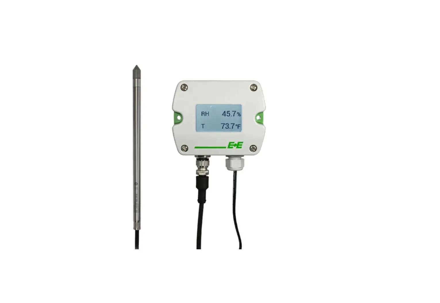
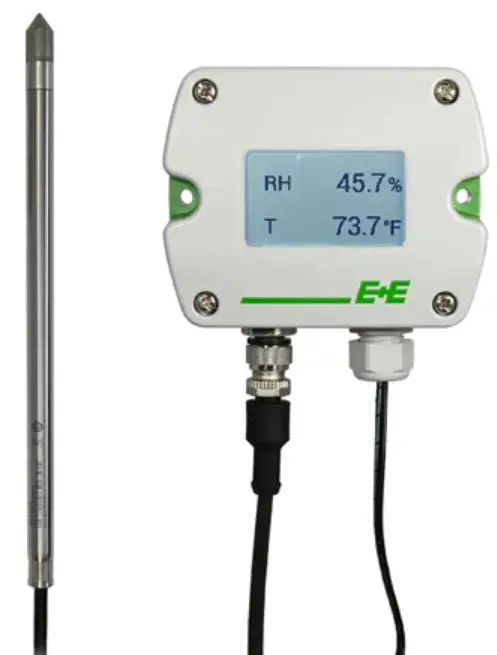
Product Description
General
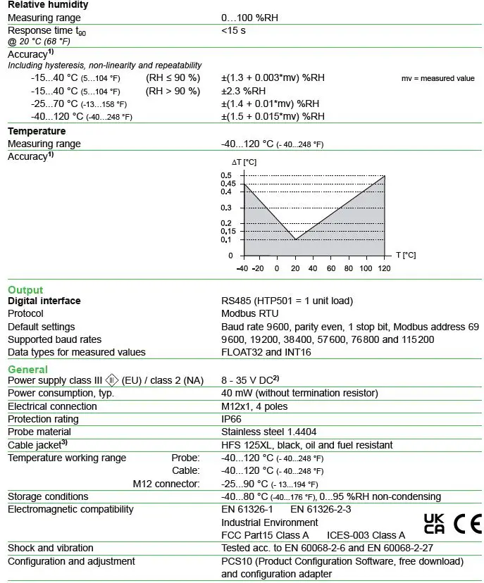
The HTP501 is a robust probe for humidity and temperature measurement in air and other non-explosive gases. It features a humidity measuring range of 0…100 %RH and a temperature measuring range of -40…120 °C (-40…248 °F). The probe calculates all humidity-related quantities
Its IP66 rating, the E+E proprietary sensor coating and the optional sensor leads protection make the probe ideal for highest requirements in terms of maximum service livetime and measurement performance.
The HTP501 is typically deployed in drying processes with high temperatures like wood, pasta or brick drying.
The HTP501 provides the measured data at its digital RS485 interface via Modbus RTU protocol. The M12x1 connector links the probe to the digital infrastructure.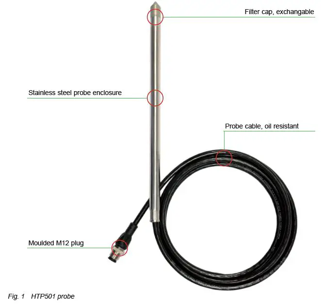
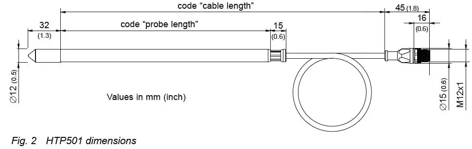
Dimensions
Electrical Connection
Important note:
The manufacturer cannot be held responsible for personal injuries or damage to property as a result of incorrect handling, installation, wiring, power supply and maintenance of the device.
The relations of electrical potential between a bus system and an HTP501 probe are characterized by the following properties:
- The bus connection is not electrically isolated from the supply connection
- The HTP501 is not electrically isolated from the supply voltage
- Each HTP501 can be supplied separately


| Pin number | Function |
| 1 | Supply voltage 24 V DC class III (Europe) / class 2 (North America) |
| 2 | B RS485 (D-) |
| 3 | GND |
| 4 | A RS485 (D+) |
Mounting and Installation
Wall and Ceiling Mount
Best measurement performance is achieved when the entire probe is located inside the environment to be monitored.
In such a case, the HTP501 may be for instance fixed onto a wall with the stainless steel mounting clip HA010225 (not included in the scope of supply, see data sheet “Accessories”), or freely hang from the ceiling on the connection cable.
Duct Mount
The probe also can be installed into a duct using the stainless steel flange HA010201 (not included in the scope of supply, see data sheet “Accessories”).
Recommendations for accurate Humidity and Temperature Measurement
- In case the HTP501 probe is not entirely located in the environment to be monitored, large temperature differences along the probe will lead to temperature gradients. These will have an influence on the accuracy. Therefore, it is of paramount importance to minimize the temperature gradients. The biggest part of the probe shall be located in the target environment and the rest shall be thermally well insulated.
- For outdoor applications the HTP501 shall be equipped with a radiation shield (HA010502) which provides protection from rain, snow and ice. This also causes a natural ventilation which largely prevents overheating of the probe in the sun and thus a distortion of the measured values.
- For highest accuracy of the measured humidity and the calculated parameters (e.g. wet bulb temperature, dew point and others), the user can set the barometric pressure at the operating point, using the PCS10 Product Configuration Software or via Modbus protocol (see chapter 5 Setup and Adjustment). The factory setting is 1013.25 mbar.
Setup and Adjustment
The HTP501 is ready to use and does not require any configuration by the user. The factory setup of HTP501 corresponds to the type number ordered. Please refer to the data sheet at www.epluse.com/htp501. The user can change the factory setup with the help the PCS10 Product Configuration Software and the Modbus configuration adapter (order code HA011018). Refer to chapter 5.1 below.
PCS10 Product Configuration Software
The PCS10 provides a convenient graphical user interface to the HTP501. To use the software for performing adjustments and changes in settings, please proceed as follows:
- Download the PCS10 Product Configuration Software from www.epluse.com/pcs10 and install it on the PC.
- Connect the HTP501 to the PC using the Modbus configuration adapter.
- Start the PCS10 software.
- Follow the instructions on the PCS10 opening page for scanning the ports and identifying the connected device.
- Click on the desired setup or adjustment mode from the main PCS10 menu on the left. Follow the online instructions of the PCS10 which are displayed when clicking the “Tutorial” button.
- Changes are uploaded to the probe by pressing the “Sync” button.
Please note: The HTP501 may not be connected to any additional power supply when using the Modbus configuration adapter HA011018.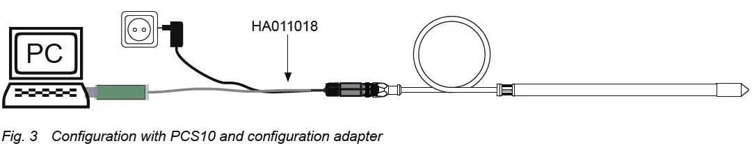
Besides an individual probe naming, the communication parameters may be changed. For the purpose of pressure compensation, the barometric air pressure at the operating site may be set. The custom Modbus map can be configured. Refer to chapter 5.4 Freely Configurable Custom Modbus Map.
A 1- and 2-point adjustment may be carried out and the factory setup may be restored again. See chapter 6.5 RH / T Adjustment and Calibration.
The configuration of an individual probe may be exported and imported.
Modbus Setup
| Factory settings | Selectable values (via PCS10) | |
| Baud rate | 9 600 | 9 600, 19 200, 38 400, 57 600, 76 800, 115 200 |
| Data bits | 8 | 8 |
| Parity | Even | None, odd, even |
| Stop bits | 1 | 1, 2 |
| Modbus address | 69 | 1…247 |
Device address, baud rate, parity and stop bits can be set via:
- PCS10 Product Configuration Software and the Modbus configuration adapter HA011018. The PCS10 can be downloaded free of charge from www.epluse.com/pcs10.
- Modbus protocol in the register 1 (0x00) and 2 (0x01).
See Application Note Modbus AN0103 (available at www.epluse.com/htp501).
The serial number as ASCII-code is located in read-only registers 1 – 8 (0x00 – 0x07, 16 bits per address).
The firmware version is located in register 9 (0x08) (bit 15…8 = major release; bit 7…0 = minor release). The sensor name is located in register 10 (0x09).
Please note: When reading the serial number or the sensor name, it is always necessary to read all 8 registers, even if the desired information requires less.
Please note: For obtaining the correct floating point values, both registers have to be read within the same reading cycle. The measured value can change between two Modbus requests, therefore exponent and mantissa may get inconsistent.
| Communication settings (INT16) | ||
| Parameter | Register number1) [Dec] | Register Address2) [Hex] |
| Write register: function code 0x06 | ||
| Modbus address (Slave ID) | 1 | 0x00 |
| Modbus protocol settings3) | 2 | 0x01 |
| Device information (INT16) | ||
| Parameter | Register number1) [Dec] | Register Address2) [Hex] |
| Read register: function code 0x03 / 0x04 | ||
| Serial number (as ASCII) | 1 | 0x00 |
| Firmware version | 9 | 0x08 |
| Sensor Name | 10 | 0x09 |
| Device status (bit decoded)4) | 602 | 0x259 |
| Application Parameter (FLOAT32) | ||
| Parameter | Register number1) [Dec] | Register Address2) [Hex] |
| Read and write register: Read function code 0x03 / Write function code: 0x10 | ||
| Air pressure5) | 5001 | 0x1388 |
- Register number starts from 1.
- Protocol address starts from 0.
- For Modbus protocol settings see Application Note Modbus AN0103 (available at www.epluse.com/htp501).
- See chapter 5.5 Device Status Indication.
- Ambient pressure in mbar, with 2 decimal digits (e.g. 1 008.25), default value 1 013.25 mbar
Tab. 3 HTP501 registers for device setup
Modbus Register Map
The measured data is saved as 32 bit floating point values (data type FLOAT32) and as 16 bit signed integer values (data type INT16).
| FLOAT32 | |||
| Parameter | Unit | Register number1) [Dec] | Register address2) [Hex] |
| Read register: function code 0x03 / 0x04 | |||
| Temperature T | °C | 1003 | 0x3EA |
| °F | 1005 | 0x3EC | |
| °K | 1009 | 0x3F0 | |
| Relative humidity RH, Uw | % RH | 1021 | 0x3FC |
| Water vapour partial pressure e | mbar | 1101 | 0x44C |
| psi | 1103 | 0x44E | |
| Dew point temperature Td | °C | 1105 | 0x450 |
| °F | 1107 | 0x452 | |
| °K | 1147 | 0x47A | |
| Wet bulb temperature Tw | °C | 1109 | 0x454 |
| °F | 1111 | 0x456 | |
| °K | 1145 | 0x478 | |
| Absolute humidity dv | g/m³ | 1113 | 0x458 |
| gr/ft³ | 1115 | 0x45A | |
| Mixing ratio r | g/kg | 1121 | 0x460 |
| gr/lb | 1123 | 0x462 | |
| Specific enthalpy h | [kJ/kg] | 1125 | 0x464 |
| [ft lbf/lb/kg] | 1127 | 0x466 | |
| [BTU/lb] | 1129 | 0x468 | |
| Frost point temperature Tf | °C | 1131 | 0x46A |
| °F | 1133 | 0x46C | |
| °K | 1149 | 0x47C | |
| Ice bulb temperature Ti | °C | 1237 | 0x4D4 |
| °F | 1239 | 0x4D6 | |
| °K | 1241 | 0x4D8 | |
| INT16 | ||||
| Parameter | Unit | Scale3) | Register number1) [Dec] | Register address2) [Hex] |
| Read register: function code 0x03 / 0x04 | ||||
| Temperature T | °C | 100 | 4002 | 0xFA1 |
| °F | 50 | 4003 | 0xFA2 | |
| °K | 50 | 4005 | 0xFA4 | |
| Relative humidity RH, Uw | % RH | 100 | 4011 | 0xFAA |
| Water vapour partial pressure e | mbar | 10 | 4051 | 0xFD2 |
| psi | 1000 | 4052 | 0xFD3 | |
| Dew point temperature Td | °C | 100 | 4053 | 0xFD4 |
| °F | 100 | 4054 | 0xFD5 | |
| °K | 100 | 4074 | 0xFE9 | |
| Wet bulb temperature Tw | °C | 100 | 4055 | 0xFD6 |
| °F | 100 | 4056 | 0xFD7 | |
| °K | 100 | 4073 | 0xFE8 | |
| Absolute humidity dv | g/m³ | 10 | 4057 | 0xFD8 |
| gr/ft³ | 10 | 4058 | 0xFD9 | |
| Mixing ratio r | g/kg | 10 | 4061 | 0xFDC |
| gr/lb | 10 | 4062 | 0xFDD | |
| Specific enthalpy h | kJ/kg | 1 | 4063 | 0xFDE |
| ft lbf/lb | 1 | 4064 | 0xFDF | |
| BTU/lb | 1 | 4065 | 0xFE0 | |
| Frost point temperature Tf | °C | 100 | 4066 | 0xFE1 |
| °F | 100 | 4067 | 0xFE2 | |
| °K | 100 | 4075 | 0xFEA | |
| Ice bulb temperature Ti | °C | 100 | 4119 | 0x1016 |
| °F | 100 | 4120 | 0x1017 | |
| °K | 50 | 4121 | 0x1018 | |
- Register number starts from 1
- Register address starts from 0
- Examples: For scale 100, the reading of 2550 means a value of 25.5. For scale 50, the reading of 2550 means a value of 51.
Tab. 4 HTP501 FLOAT32 and INT16 measured data registers
Freely Configurable Custom Modbus Map
It is possible to map measured value/status registers arbitrarily in a block with up to 20 registers provided for this purpose. This means that registers of interest may be mapped in an area with consecutive registers, so that important values can be queried with a single command in one block.
The custom map can be configured via:
- PCS10 Product Configuration Software and the Modbus configuration adapter HA011018. The PCS10 can be downloaded free of charge from www.epluse.com/pcs10.
- Modbus protocol commands, refer to the example in chapter 5.6 Modbus RTU Examples.
The register block for the configuration of the customisable Modbus map consists of the registers 6001
(0x1770) to 6010 (0x1779). For the blockwise query of the measured values behind Modbus registers 3001 (0xBB8) to 3020 (0xBCB), the firmware accesses this configuration area and thus gets the information which measured value/status registers are to be output. A maximum of 10 user-defined registers can be mapped. The table below shows an example:
| Registers … | … with these assigned measurands … | … map to registers … | … mirrored from source registers | |||||
| Dec | Hex | Meas. | Unit | Type | Dec | Hex | Dec | Hex |
| Function code 0x10 | Function code 0x03 / 0x04 | |||||||
| 6001 | 0x1770 | Status | – | INT16 | 3001 | 0xBB8 | 602 | 0x259 |
| 6002 | 0x1771 | RH | % | FLOAT32 | 3002 | 0xBB9 | 1021 | 0x3FC |
| FLOAT32 | 3003 | 0xBBA | 1022 | 0x3FD | ||||
| 6003 | 0x1772 | T | °C | FLOAT32 | 3004 | 0xBBB | 1003 | 0x3EA |
| FLOAT32 | 3005 | 0xBBC | 1004 | 0x3EB | ||||
| 6004 | 0x1773 | Td | °C | FLOAT32 | 3006 | 0xBBD | 1105 | 0x450 |
| FLOAT32 | 3007 | 0xBBE | 1106 | 0x451 | ||||
| 6005 | 0x1774 | Tw | °C | FLOAT32 | 3008 | 0xBBF | 1109 | 0x454 |
| FLOAT32 | 3009 | 0xBC0 | 1110 | 0x455 | ||||
| 6006 | 0x1775 | T | °F | FLOAT32 | 3010 | 0xBC1 | 1005 | 0x3EC |
| FLOAT32 | 3011 | 0xBC2 | 1006 | 0x3ED | ||||
| 6007 | 0x1776 | Td | °F | FLOAT32 | 3012 | 0xBC3 | 1107 | 0x452 |
| FLOAT32 | 3013 | 0xBC4 | 1108 | 0x453 | ||||
| 6008 | 0x1777 | RH | % | INT16 | 3014 | 0xBC5 | 4011 | 0xFAA |
| 6009 | 0x1778 | T | °C | INT16 | 3015 | 0xBC6 | 4002 | 0xFA1 |
| 6010 | 0x1779 | T | °F | INT16 | 3016 | 0xBC7 | 4003 | 0xFA2 |
| 3017 | 0xBC8 | 65536 | 0xFFFF | |||||
| 3018 | 0xBC9 | 65536 | 0xFFFF | |||||
| 3019 | 0xBCA | 65536 | 0xFFFF | |||||
| 3020 | 0xBCB | 65536 | 0xFFFF | |||||
Tab. 5 Custom Modbus map example
Device Status Indication
If a critical error occurs, all Modbus values are set to NaN (according to IEEE754 for data type FLOAT32) or to 0x8000 (INT16). It is possible to read out all status and error information via Modbus register 602 (0x259). Errors are displayed in bit-coded form. If an event is present, the corresponding bit is set to 1.
Measured values outside the measuring range are limited with the corresponding limit value.
| Error Bits | Description | Recommended action |
| Bit 0 | Error: Hardware T-sensing | Return the faulty unit to E+E for service |
| Bit 1 | Error: Short circuit of T sensing element | 1. Clean sensing head acc. to cleaning instructions 2. Return the faulty unit to E+E for service |
| Bit 2 | Error: Open loop of T sensing element | Return the faulty unit to E+E for service |
| Bit 3 | Error: Short circuit of RH sensing element | 1. Clean sensing head acc. to cleaning instructions 2. Return the faulty unit to E+E for service |
| Bit 4 | Error: Open loop of RH sensing element or heavy pollution | 1. Clean sensing head acc. to cleaning instructions 2. Return the faulty unit to E+E for service |
| Bit 5 | Warning: Polluted RH sensing element | Clean sensing head acc. to cleaning instructions |
| Bit 6 | Warning: Temperature below allowed working range | Observe the lower working range limit |
| Bit 7 | Warning: Temperature above allowed working range | Observe the upper working range limit |
| Bit 8 | Error: T sensing element defective | Return the faulty unit to E+E for service |
| Bit 9 | Warning: RH below allowed working range | Observe the lower working range limit |
| Bit 10 | Warning: RH above allowed working range | Observe the upper working range limit |
| Bit 11 | Error: RH sensing element defective | Return the faulty unit to E+E for service |
| Bit 12 | Error: Hardware RH sensing | Return the faulty unit to E+E for service |
Tab. 6 Device status indication register
Modbus RTU Examples
The HTP501’s Modbus address is 69 [0x45].
Please refer to
- MODBUS APPLICATION PROTOCOL SPECIFICATION V1.1b3, chapter 6: www.modbus.org/docs/Modbus_Application_Protocol_V1_1b3.pdf
- E+E Application Note Modbus AN0103 (available at www.epluse.com/htp501)
Read the temperature (FLOAT32) T = 25.087642669677734375 °C from register address 0x3EA: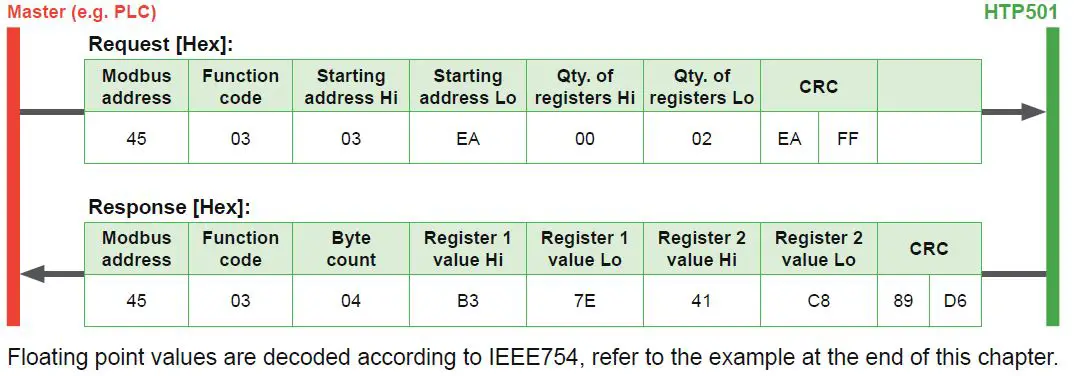
Read register from custom modbus map
address 0x0BB8-0x0BB9, unconfigured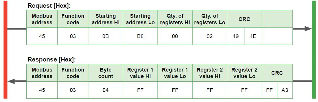
Mapping custom Modbus map
assign RH (register address 0x3FC) and T [°C] (register address 0x3EA) to the custom Modbus map, starting address 0xBB8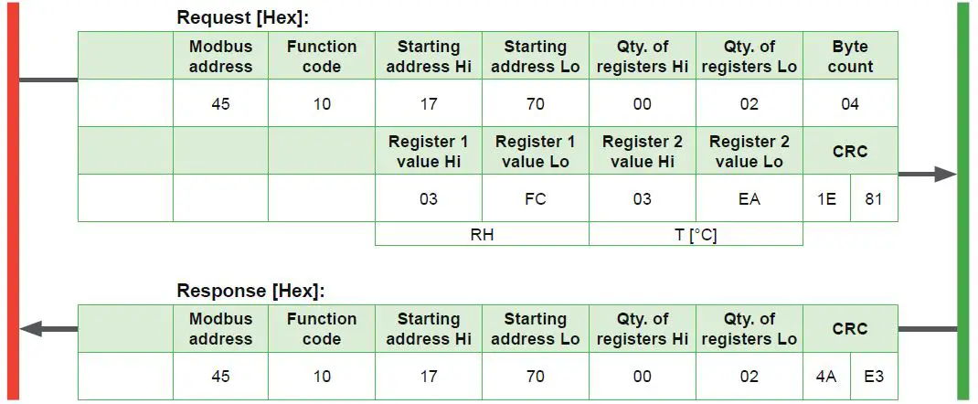
Poll register address 0xBB8 (RH mapped)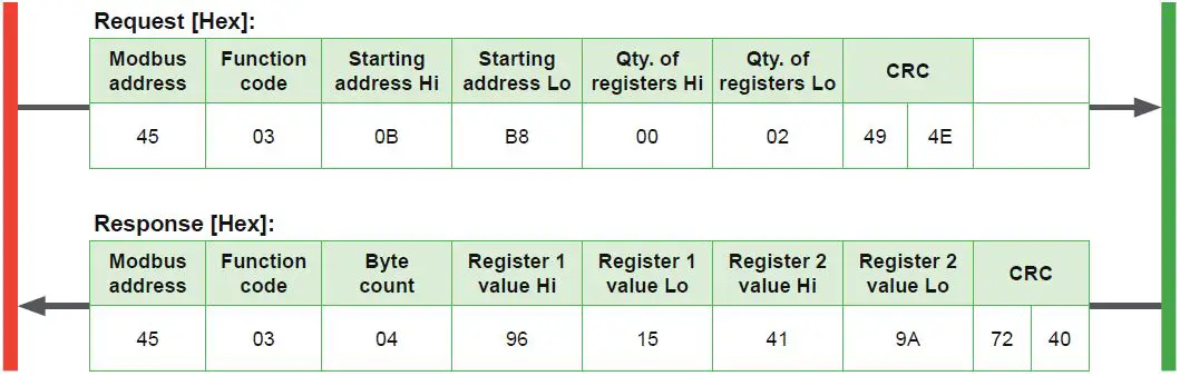 Poll register address 0xBB8-0xBBD (RH and T mapped, one register empty)
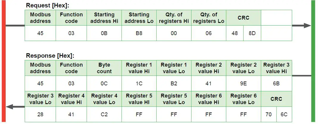
Decoding of floating point values:
Floating point values are stored according IEEE754. The byte pairs 1, 2 and 3, 4 are reorganised as follows:
| MMMMMMMM | MMMMMMMM | SEEEEEEE | EMMMMMMM |
| Byte 3 | Byte 4 | Byte 1 | Byte 2 |
Example (numbers taken from T reading in first Modbus request/response example in this chapter):
| Response [Hex] | |||
| Byte 1 (Register 2 – Hi) | Byte 2 (Register 2 – Lo) | Byte 3 (Register 1 – Hi) | Byte 4 (Register 1 – Lo) |
| 41 | C8 | B3 | 7E |
| 0100 0001 | 1100 1000 | 1011 0011 | 0111 1110 |
| SEEE EEEE | EMMM MMMM | MMMM MMMM | MMMM MMMM |
| Decimal value: 25.087642669677734375 | |||
Maintenance and Service
HTP501 does not require any special maintenance, nevertheless for high accurate measurements especially over wide RH and T ranges it is recommended to calibrate the probe every 12 months. If needed, the enclosure may be cleaned and the device may be re-adjusted as described below.
Cleaning
Use a damp soft cloth to remove deposits of dust or dirt from the exterior of the probe. Do not use any solvents or abrasive cleaning agents.
In case of dusty, oily and polluted environment:
- Use a damp soft cloth to remove deposits of dust or dirt from the exterior of the probe. Do not use any solvents or abrasive cleaning agents.
- The filter cap shall be replaced once in a while with an E+E original one (see below).
- If needed, the sensing element of the humidity probe can be cleaned by the user (see cleaning instructions – www.epluse.com/cleaning-instructions).
Filter Cap Replacement
In a dusty or polluted environment it might be necessary to replace the filter cap once in a while. In most of the cases, a clogged filter shows visible contamination or dirt. Longer response time of the humidity measurement also indicates a clogged filter cap. In such cases, replace the filter by a new, original one, see 6.6 Spare Parts.
Procedure
- Turn the filter cap counter-clockwise for removing it.
- Install the new filter cap finger tight by turning it clockwise.
While replacing the filter cap take very good care to not touch or rub the sensing element.
Protection during Site Cleaning Operations
During site cleaning or sterilization process, if the EE072 remains on the measuring site the sensing head can be protected with the optional protection cap for 12 mm (0.47”) probe (HA010783, see datasheet “Accessories”).
In case the probe is removed from the site, it is recommended to apply the protection cap for the M12 cable socket (HA010781) and the one for the EE072 M12 plug of (HA010782).
Fig. 4 Protection cap for Ø12 mm (0.47”) probe (ordering code HA010783)
Fig. 5 Protection cap M12 Fig. 5 Protection cap M12 
Fig. 6 Protection cap M12 female connector (ordering code HA010782)
Repairs
Repairs may be carried out by the manufacturer only. The attempt of unauthorized repair excludes any warranty claims.
RH / T Adjustment and Calibration
Definition
- Adjustment
the specimen is brought in line with the reference. - Calibration
the specimen is compared with a reference and its deviation from the reference is documented.
Humidity calibration and adjustment
Depending on the application and the requirements of certain industries, there might arise the need for periodical humidity calibration (comparison with a reference) or adjustment (bringing the device in line with a reference).
Calibration and adjustment at E+E Elektronik
Calibration and/or adjustment can be performed in the E+E Elektronik calibration laboratory. For information on the E+E capabilities in ISO or accredited calibration please see www.eplusecal.com.
Calibration and adjustment by the user
Depending on the level of accuracy required, the humidity reference can be:
- Humidity calibrator (e.g. Humor 20), please see www.epluse.com/humor20.
- Handheld device (e.g. Omniport 30), please see www.epluse.com/omniport30.
- Humidity standards (e.g. Humidity Calibration Kit), please see www.epluse.com/htp501.
Spare Parts
| Description | Order code |
| Metal grid with polycarbonate body | HA010106 |
| Stainless steel sintered filter | HA010117 |
| PTFE filter | HA010105 |
Accessories
| Item | Order code |
| E+E Product Configuration Software (Free download: www.epluse.com/pcs10) | PCS10 |
| Modbus configuration adapter | HA011018 |
| Stainless steel mounting flange | HA010201 |
| Stainless steel wall mounting clip | HA010225 |
| T-coupler M12 – M12 | HA030204 |
| Protection cap for M12 socket | HA010781 |
| Protection cap for M12 plug | HA010782 |
| Protection cap for 12 mm probe | HA010783 |
| Drip water protection | HA010503 |
Technical Data
- Traceable to international standards, administrated by NIST, PTB, BEV…
The accuracy statement includes the uncertainty of the factory calibration with an enhancement factor k=2 (2-times standard deviation). The accuracy was calculated in accordance with EA-4/02 and with regard to GUM (Guide to the Expression of Uncertainty in Measurement). - USA & Canada class 2 supply required, max. supply voltage 30 V DC
- Please mind the mounting and installing instructions included in the user manual.
HEADQUARTERS
E+E Elektronik Ges.m.b.H. Langwiesen 7
4209 Engerwitzdorf Austria
Tel.: +43 7235 605-0
E-mail: [email protected]
Web: www.epluse.com
SUBSIDIARIES
E+E Elektronik China
18F, Kaidi Financial Building, No.1088 XiangYin Road 200433 Shanghai
Tel.: +86 21 6117 6129
E-mail: [email protected]
E+E Elektronik France
47 Avenue de l‘Europe 92310 Sèvres
Tel.: +33 4 74 72 35 82
E-mail: [email protected]
E+E Elektronik Germany
Obere Zeil 2
61440 Oberursel
Tel.: +49 6171 69411-0
E-mail: [email protected]
E+E Elektronik India 801, Sakhi Vihar Road 400072 Mumbai
Tel.: +91 990 440 5400
E-mail: [email protected]
E+E Elektronik Italy
Via Alghero 17/19
20128 Milano (MI)
Tel.: +39 02 2707 86 36
E-mail: [email protected]
E+E Elektronik Korea Suite 2001, Heungdeok IT Valley Towerdong, 13, Heungdeok 1-ro, Giheung-gu 16954 Yongin-si, Gyeonggi-do
Tel.: +82 31 732 6050
E-mail: [email protected]
E+E Elektronik USA
333 East State Parkway Schaumburg, IL 60173
Tel.: +1 847 490 0520
E-mail: [email protected]
References
 Sensor Technology: Humidity, CO2, Flow & Temperature Measurement
-
Sensor Technology: Humidity, CO2, Flow & Temperature Measurement
-
epluse.com/cleaning-instructions
-
Digital humidity and temperature probe
-
Humidity calibration with HUMOR 20 high-end humidity calibrator
-
Multifunctional hand-held meter
-
epluse.com/pcs10
-
Accredited calibration laboratory | E+E Elektronik


