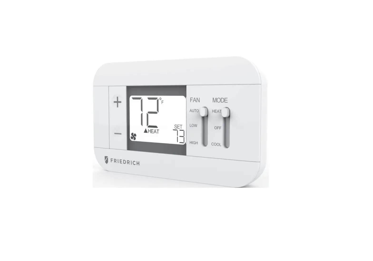
FRIEDRICH RT7 Digital Remote Wall Thermostat Installation Guide
The Friedrich RT7 is a nonprogrammable electronic thermostat, which can be used with the following heating/cooling applications:
- Single Stage Heat – Cool PTAC Units
- Singe Stage Heat Pump PTAC Units with or without Electric Heat
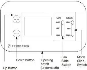
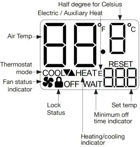
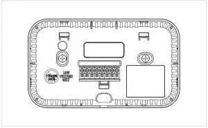
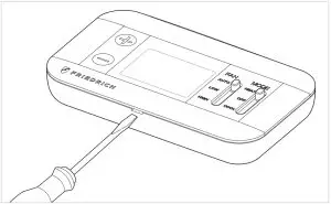
Parts Diagram
Specifications
- Input Voltage: 19 to 30 VAC
- Output Rating: Max. 1.5A per terminal (3A total)
- Temperature Control: 45°F to 90°F (7°C to 32°C)
- Temperature Accuracy: ± 1°F (± 0.5°C)
Safety Information
- This thermostat is for LOW voltage applications only.
- Turn OFF electricity to all heating and cooling components.
- All wiring must conform to applicable local and national building and electrical codes and ordinances.
Included in Package
- Thermostat
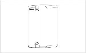
- J-Box mounting plate/ decorative trim plate
- J-box mounting screws
- Dry wall anchors and mounting screws
- Wiring labels
- GL to GH Jumper wire
Installing the Thermostat
- If painting or construction is still ongoing, cover the thermostat completely or wait until work is complete before mounting thermostat.
- Mount the thermostat on an inside wall about five feet above the floor in an area that has good circulation but is not directly affected by a vent or duct.
- Ensure power is switched OFF at the PTAC unit
Mounting directly on the wall
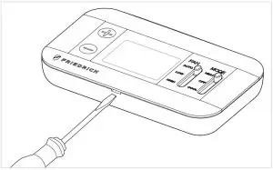
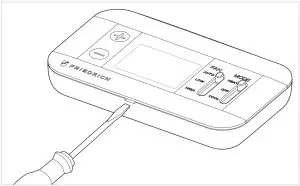
- Use a flat head screw driver to separate the front and back housing of the thermostat

- If new mounting holes are needed, mark the placement of the new mounting holes through the thermostat base. Using a 3/16″ drill bit, drill the holes you have marked and insert the supplied wall anchors.

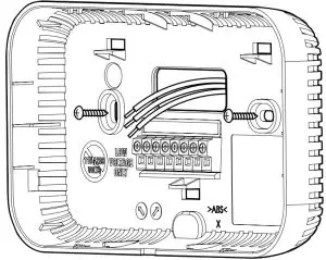
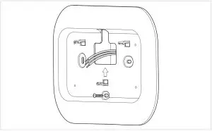
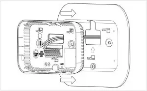
- Feed the wires through the hole in the back housing of the thermostat and then screw the back housing to the wall

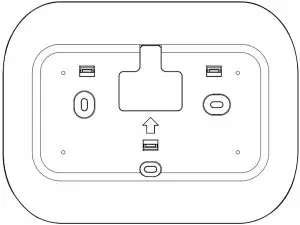
Mounting directly on wall with trim plate
- If new mounting holes are needed, mark the placement of the new horizontal mounting holes through the trim plate base. Using a 3/16″ drill bit, drill the holes you have marked and insert the supplied wall anchors.

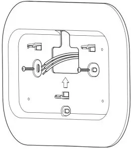
- Feed the wires through the hole in the trim plate and screw the trim plate to the wall

- Use a flat head screw driver to separate the front and back housing of the thermostat
- Feed the wires through the back housing of the thermostat and then snap the back housing to the trim plate
- Your thermostat base should now be securely fixed to the wall

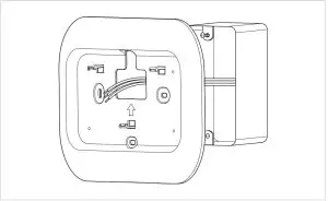
Mounting on Junction Box
- Install junction box
- Feed the wires through the hole in the trim plate and hang the trim plate on the top screw

- Insert mounting screw into top of junction box until there is approximately 1/8″ gap between the screw head and the wall

- Use a flat head screw driver to separate the front and back housing of the thermostat
- Feed the wires through the back housing of the thermostat and then snap the back housing to the trim plate
- Your thermostat base should now be securely fixed to the wall
- Using the WIRING DIAGRAMS section, wire each terminal on the thermostat base. Ensure that the bare end is fully seated into the connector, then tighten securely.
Pull gently on wires to ensure they are secure. - Important: For Heat Pump systems additional configuration steps are necessary. View the WIRING DIAGRAMS: Heat Pump section for details.

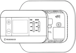
- Return the thermostat front cabinet to its base by hooking the top first and then gently swinging the bottom of the thermostat into place.
- Restore power back to heating and cooling components and thermostat.
- See INSTALLER SETTINGS MENU section, to adjust the required settings needed for each system type.
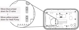
WIRING DIAGRAM: Heat Pump

Note 1: Make the following jumper position changes and Installer Settings for Heat Pump units
System Type | Changeover valve type | Required action |
Heat Pump | B | 1. Move yellow PCB jumper to HP position 2. Set Installer Settings Menu #06 to HP |
O | 1. Move yellow PCB jumper to HP position 2. Move blue PCB jumper to O position 3. Set Installer Settings Menu #06 to HP |
Note 2: The “W2” terminal is used to call for Electric/Auxiliary heat. If your Heat Pump PTAC does not have Electric heat, then the “W2” terminal should not be used and Installer Settings menu 10 (Aux. Stage Offset) should be set to “OFF”.
Note 3: For PTAC units with only one fan speed (single “G” fan wire), add a jumper wire to bridge together “GH” and “GL”. Connect your fan wire to either terminal after jumper wire has been added.
WIRING DIAGRAM: Heat – Cool

Note 1: If connecting to a Cool only PTAC unit, the W1 wire terminals will not be used.
Note 2: For PTAC units with only one fan speed (single “G” fan wire), add a jumper wire to bridge together “GH” and “GL”. Connect your fan wire to either terminal after jumper wire has been added.
INSTALLER SETTINGS
HOW TO ENTER
- Place the Mode Slide Switch to OFF mode
- Hold UP for 5 seconds to enter the installer setting
HOW TO NAVIGATE
- Press UP or DOWN to change the setting value
- Hold UP or DOWN for 2 seconds to save the setting value and proceed to the next setting option
HOW TO EXIT
- When finished, leave thermostat without pressing any buttons for 60 seconds or change Mode Slide Switch position
- Note: You must hold UP or DOWN for 2 seconds to save setting value
| Menu Number | Function Description | Selectable Options | Default setting |
| 1 | Temperature Scale | F: Fahrenheit C: Celsius | F |
| 2 | Temperature Calibration | +/- 5.4°F | 0.0°F |
| 3 | (Not Used) | ||
| 4 | Max Heat Set Temp | F: 60 to 90 (5°F step) | 80°F |
| 5 | Min Cool Set Temp | F: 60 to 80 (5°F step) | 65°F |
| 6 | System Type | H-C: Heat-Cool HP: Heat Pump | H-C |
| 7 | (Not Used) | ||
| 8 | (Not Used) | ||
| 8 | Stage 1 Temperature Control Swing | ±0.25°F ±0.50°F ±1.00°F ±2.25°F | 0.50°F |
| 10 | Auxiliary Stage Cut-In Offset (only used for HP system type) | OFF (No Electric / Auxiliary heat) -3.0 to -8.0°F (1°F step) | -4.0°F |
| 11 | (Not Used) | ||
| 12 | (Not Used) | ||
| 13 | (Not Used) | ||
| 14 | (Not Used) | ||
| 15 | (Not Used) | ||
| 17 | Always On Backlight | OFF: 10s timeout ON: always ON | OFF |
| 18 | Reset to default set temperatures after each mode change | ON: uses default temperatures after each mode change (see menu 19 and 20) OFF: Maintain last set temperature for each mode | ON |
| 19 | Default heat mode set temperature | 60°F to Max Heat Set Temp | 70°F |
| 20 | Default cool mode set temperature | Min Cool Set Temp to 80°F | 74°F |
| 98 | Minimum off time – Compressor protection | NO: Immediate off/ on switching YES: 3-minute minimum off time enforced | NO |
| 99 | Reset | NO: no reset YES: ex-factory reset | NO |
NORMAL OPERATION
THERMOSTAT SYSTEM MODE SWITCH POSITIONS:
- HEAT: thermostat permits heating operation
- OFF: thermostat stops all heating or cooling functions
- COOL: thermostat permits cooling operation
THERMOSTAT FAN SWITCH POSITIONS:
- AUTO position: fan operates in low speed mode as needed during a call for heating or cooling activation only.
- LOW position: fan operates continuously in low speed. Heat/Cool will turn on/off in background as needed.
- HIGH position: fan operates continuously in high speed. Heat/Cool will turn on/off in background as needed.
THERMOSTAT BUTTONS:
- UP / DOWN: used for raising or lowering the target set temperature and selecting user options and settings in the display screen.
- Note: to adjust the target set temperature, first ensure that the thermostat is in either HEAT or COOL mode and press either UP or DOWN until the desired target temperature is reached. Pressing UP or DOWN will have no effect when the thermostat is in OFF mode.
SETTING A KEYPAD / FRONT PANEL LOCKOUT:
- While in either HEAT or COOL mode, a keypad lockout can be introduced which will prevent any temperature adjustment from being made by the user. Even while locked, any button press will illuminate the display backlight.
- To activate (and deactivate) the keypad lockout, set Mode Slide Switch to either HEAT or COOL, hold UP for 5 seconds . When the keypad is locked, a padlock will appear in the lower left corner of the display

Friedrich Air Conditioning Co.
10001 Reunion Pl Suite 500,
San Antonio, TX 78216
1-877-599-5665
www.friedrich.com
Documents / Resources
 | FRIEDRICH RT7 Digital Remote Wall Thermostat [pdf] Installation Guide RT7, Digital Remote Wall Thermostat |


