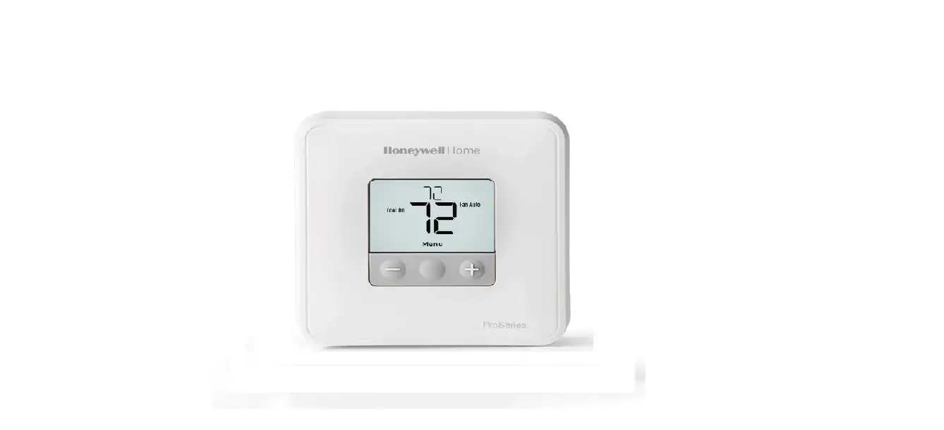

Honeywell T6 Pro Programmable Thermostat
 Honeywell T6 Manual – Pro Series Thermostat
Installation Instructions
Package Includes:
- T6 Pro Thermostat
- UWP Mounting System
- Honeywell Standard Installation Adapter (J-box adapter)
- Honeywell Decorative Cover Plate – Small; size 4-49/64 in x 4-49/64 in x 11/32 in (121 mm x 121 mm x 9 mm)
- Screws and anchors
- 2 AA Batteries
- Installation Instructions and User Guide
Optional Cover Plate installation
NOTE: If Optional Cover Plate is not required, see “UWP Mounting System installation” on next page.
Use the Optional Cover Plate when:
- Mounting the thermostat to an electrical junction box
- Or when you need to cover paint gap from old thermostat.
- Separate the Junction Box Adapter from the Cover Plate. See Figure 1.

- Mount the Junction Box Adapter to the wall or an electrical box using any of the eight screw holes. Insert and tighten mounting screws supplied with Cover Plate Kit. Do not overtighten. See Figure 2. Make sure the Adapter Plate is level.
- Attach the UWP by hanging it on the top hook of the Junction Box Adapter and then snapping the bottom of the UWP in place. See Figure 3.

- Snap the Cover Plate onto the Junction Box Adapter. See Figure 4.

- Before starting, turn the power off at the breaker box or switch. Open package to find the UWP. See Figure 5.

- Position the UWP on wall. Level and mark hole positions. See Figure 6. Drill holes at marked positions, and then lightly tap supplied wall anchors into the wall using a hammer. ‒ Drill 7/32” holes for drywall.
- Pull the door open and insert the wires through wiring hole of the UWP. See Figure 7.

- Place the UWP over the wall anchors. Insert and tighten mounting screws supplied with the UWP. Do not over tighten. Tighten until the UWP no longer moves. Close the door. See Figure 8.


Other top Honeywell manual’s:
- Honeywell Pro Series Thermostat Manual
- Honeywell VisionPRO Series Programmable Thermostat Installation Guide
- Honeywell Pro 3000 Series Non-Programmable Digital Thermostat Instructions
Power options

Insert R and C wires into designated terminals for primary AC power (C terminal is optional if batteries are installed, but it is recommended). Remove wires by depressing the terminal tabs.

Insert AA batteries for primary or backup power.
Setting Slider Tabs
Set R Slider Tab:
- Use built-in jumper (R Slider Tab) to differentiate between one or two transformer systems.
- If there is only one R wire, and it is connected to the R, Rc, or RH terminal, set the slider to the up position (1 wire).
- If there is one wire connected to the R terminal and one wire connected to the Rc terminal, set the slider to the down position (2 wires).


NOTE: Slider Tabs for U terminals should be left in place for T6 Pro models.
Wiring terminal designations

Wiring conventional systems: forced air and hydronics
1H/1C System (1 transformer):
- R Power [1]
- Rc [R+Rc joined by Slider Tab] [2]
- Y Compressor contactor
- C 24VAC common [3]
- W Heat relay
- G Fan relay
1H/1C System (2 transformers):
- Power (heating transformer) [1]
- Rc Power (cooling transformer) [1]
- Y Compressor contactor
- C 24VAC common [3, 4]
- W Heat relay
- G Fan relay
Heat-only System
- R Power [1]
- Rc [R+Rc joined by Slider Tab] [2]
- C 24VAC common [3]
- W Heat relay
Heat-only System with Fan
- R Power [1]
- Rc [R+Rc joined by Slider Tab] [2]
- C 24VAC common [3]
- W Heat relay
- G Fan relay
Heat-only System (Series 20) [5]:
- R Series 20 valve terminal “R” [1]
- Rc [R+Rc joined by Slider Tab] [2]
- Y Series 20 valve terminal “W”
- C 24VAC common [3]
- W Series 20 valve terminal “B”
Cool-only System:
- R Power [1]
- Rc [R+Rc joined by Slider Tab] [2]
- Y Compressor contactor
- C 24VAC common [3]
- G Fan relay
Heat-only System (power open zone valve) [5]:
- R Power [1]
- Rc [R+Rc joined by Slider Tab] [2]
- W Valve
- C 24VAC common [3]
2H/2C System (1 transformer) [6]:
- R Power [1]
- Rc [R+Rc joined by Slider Tab] [2]
- Y Compressor contactor (stage 1)
- C 24VAC common [3]
- W Heat relay (stage 1)
- G Fan relay
- W2 Heat relay (stage 2)
- Y2 Compressor contactor (stage 2)
NOTES:
Wire specifications: Use 18- to 22-gauge thermostat wire. Shielded cable is not required.
- Power supply. Provide disconnect means and overload protection as required.
- Move R-Slider Tab on UWP to the R setting. For more information, see “Setting Slider Tabs” on page 3
- Optional 24VAC common connection.
- Common connection must come from cooling transformer.
- In ISU set Heat system type to Radiant Heat. Set number of cool stages to 0.
- In Installer Setup, set system type to 2Heat/2Cool Conventional.
Wiring heat pump systems
Shaded areas below apply only to TH6320U/TH6220U or as otherwise noted.
1H/1C Heat Pump System:
- R Power [1]
- Rc [R+Rc joined by Slider Tab] [2]
- Y Compressor contactor
- C 24VAC common [3]
- O/B Changeover valve [7]
- G Fan relay
2H/1C Heat Pump System [8]:
- R Power [1]
- Rc [R+Rc joined by Slider Tab] [2]
- Y Compressor contactor
- C 24VAC common [3]
- O/B Changeover valve [7]
- G Fan relay Aux Auxiliary heat
- E Emergency heat relay
- L Heat pump fault input
Thermostat mounting
- Push excess wire back into the wall opening.
- Close the UWP door. It should remain closed without bulging.
- Align the UWP with the thermostat, and push gently until the thermostat snaps in place.
- Turn the power on at the breaker box or switch.


System operation settings
- Press the Mode button to cycle to the next available System mode.
- Cycle through the modes until the required System mode is displayed and leave it to activate


NOTE: Available System modes vary by model and system settings.
System modes:
- Auto
- Heat
- Cool
- Em Heat
- Off
Fan operation settings
- Press the Fan button to cycle to the next available Fan mode.
- Cycle through the modes until the required Fan mode is displayed and leave it to activate.


NOTE: Available Fan modes vary with system settings.
Fan modes:
- Auto: Fan runs only when the heating or cooling system is on.
- On: Fan is always on.
- Circ: Fan runs randomly about 33% of the time
Installer setup (ISU)

- Press and hold CENTER and buttons for approximately 3 seconds to enter advanced menu.
- Press Select to enter ISU.
- Press Select to cycle through menu setup options.
- Press or to change values or select from available options.
- Press Select and confirm your settings or press Back to ignore changes and return to ISU menu screen to continue editing another setup option.
- To finish setup process and save your setting, press Home and return to Home screen.

NOTE: A complete list of all setup (ISU) parameters and options starts below and continues through page 10.
Advanced setup options (ISU)
NOTE: Depending on system settings, not all options may be available.


Installer system test
To perform a System Test:
- Press and hold CENTER and
 buttons for approximately 3 seconds to enter advanced menu.
 - Use to go to TEST. Press Select to enter System Test.
- Use to change between Heat, Cool, Fan, Em Heat, or Ver (thermostat version information). Press Select.
- Press to turn stages on one at a time, and press
 to turn them off.
 - Use the Home button to exit the System Test.


System test System status

Specifications
- Temperature Ranges:
Heat: 40 °F to 90 °F (4.5 °C to 32.0 °C)
Cool: 50 °F to 99 °F (10.0 °C to 37.0 °C) - Working Ambient Temperature:
32 °F to 120 °F (0 C° to 48.9 °C) - Operating Ambient Temperature:
37 °F to 102 °F (2.8 °C to 38.9 °C) - Shipping Temperature:
-20 °F to 120 °F (-28.9 °C to 48.9 °C) - Operating Relative Humidity:
5% to 90% (non-condensing) - Physical Dimensions in inches (mm) (H x W x D):
4-1/16” H x 4-1/16” W x 1-5/32” D
103.5 mm H x 103.5 mm W x 29 mm D
Electrical Ratings

 CAUTION: ELECTRICAL HAZARD Can cause electrical shock or equipment damage. Disconnect power before beginning installation.
CAUTION: EQUIPMENT DAMAGE HAZARD Compressor protection is bypassed during testing. To prevent equipment damage, avoid cycling the compressor quickly
CAUTION: MERCURY NOTICE If this product is replacing a control that contains mercury in a sealed tube, do not place the old control in the trash. Contact your local waste management authority for instructions regarding recycling and proper disposal.
FAQs
Yes, it’s a low-voltage (24 VAC) thermostat, compatible with the vast majority of forced air HVAC systems.
Yes, but “System Changeover” in the ISU menu must be changed from the default value of 0 (“Manual”) to 1 (“Automatic”), then “Auto” can be selected as one of the operating modes using the “Mode” button.
no. need a wyfi stat for that. But is a good thermostat.
Yes the t6 lyric
This thermostat does not have a wifi connection it will not work with Alexa, phone, or any device. It must be programmed on the thermostat itself by pushing buttons although it is digital. It’s a very nice thermostat and works great.
It has battery back up.
2-programs per day or 4-programs per day, or no programs per day adjustable for 5-1-1, or 5-2days, as far as off and on, can not do that just to the lowest, or highest temp.
If by dual fuel you mean one source for heat and a different source for A/C, then yes. I have gas heat and electric air on two separate units and have this thermostat controlling both units.
T4 is a basic stat that works on batteries or 24vac, it is no programmable good for milli volt fireplaces, furnaces. T5 does not have emergency heat for heat pumps, t6 has programming capability select able requires 24 vac from furnace. still has batteries just to maintain set back programs
You don’t need the C wire on this model as it takes batteries. The wifi model will require a C wire however.
1-1/8″
I just bought two and this looks like mine. They do work beautifully…
Yes, plate is 4-3/4 square.
Sometimes annoying. To change one time, cycle or temp program, you have to go through too many program changes. For instance you have to go through separate ac, and heat programs for each step. Temporary or locked permanent temperature changes however are easy.
VIDEO
Customer assistance
For assistance with this product, please visit customer.honeywell.com.
Or call Honeywell Customer Care toll-free at 1-800-468-1502.
Honeywell T6 Manual – Pro Series Thermostat – Optimized PDF
Honeywell T6 Manual – Pro Series Thermostat – Original PDF
T6 Installation Instructions [pdf]
T6 Thermostat Manual [pdf]
Honeywell T6 Manual – Pro Series Thermostat
Click to Read More Honeywell Manuals


")

