DEMI Q5 Signal 23cm Transverter
Q5 SIGNAL 23cm TRANSVERTER
Part Number
L23-___HP___
SN___________
Transverter Configuration
| Power Out Maximum: | □ 25 W □ 50 W | |
| Noise Figure and Gain: | <1.0 dB maximum @ 20 dB conversion gain minimum | |
| DC Power Requirement: | 11.5 – 15.5 VDC @ □ 10 A Max □ 20 A Max | |
| IF Option: | □ Common □ Separate TX and RX (Split) | |
| RF Option: | □ Common □ Separate TX and RX (Split) | |
| IF Drive Level: | ||
| IF Drive Sense: | □ Enabled | |
| Keying Option: | □ PTT-L (To Ground) □ PTT-H (Positive Voltage) | |
| LO Stability: | □ Standard (1ppm) □ High (0.28ppm) | |
| Aux Connector Pin # | Transmit | Receive |
| 1 (Sequencer step 1) | □ High □ Low □ Open | □ High □ Low □ Open |
| 2 (Sequencer step 2) | □ High □ Low □ Open | □ High □ Low □ Open |
| 3 (Sequencer step 3) | □ High □ Low □ Open | □ High □ Low □ Open |
| 4 | ||
| 5 | PTT | PTT |
| 6,7,8,9 | Ground | Ground |
Additional Specified Options
Configuration Overview
This transverter is designed to interface and operate with most High Frequency transceivers that are available on the market today. Your assembled unit has been configured to your specifications to interface with your desired transceiver. This configuration may be changed or altered at any time if you desire to utilize a different transceiver or change your system configuration. Let’s review your configuration and verify that your interface will be trouble free. Please refer to the front page.
Part Number Verification: All transverters contain the operating frequency (or band) within the part number. For example, L23-28HP means that 1296 MHz is converted to 28 MHz. If you ordered a special frequency conversion, it will be listed here. Also, please understand that the conversion is simple math. If you desire to operate on 1296.100 MHz with your L23-28HP, it will require you to tune your transceiver to 28.100 MHz.
Power Out Maximum: The maximum output power will be indicated. This level is the linear output power level that should not be exceeded if linear operation is expected. The transverter may be capable of producing higher output power. But it is not recommended because of excessive heating that will interfere with its frequency stability while producing excessive distortion products.
Noise Figure and Gain: The noise figure and gain listed are typical and most transverters exceed these specifications. In utilizing the latest PHEMPT technology, we have designed the complete receive section of the transverter with extra filtering and gain management in mind. There is also a RXIF gain control that is adjusted by the user to set the “S” meter level on the transceiver. External receive pre-amplification interfacing will be covered later in this document.
DC Power Requirement: The DC power requirement is listed and should be used as a guideline. Please include some “head room” in your power supply to eliminate voltage drop delivered to the transverter. We recommend a 15-Amp supply for the 25W models and a 30-Amp supply for 50W models.
RF Option: The RF option is either a single port (Common RF) for both TX and RX or there will be two separate ports, (Split RF) one RX and one TX. The transverter may be changed from Common to Split if the user desires. The TR relays are controlled by the Push-To-Talk (PTT) circuit.
IF Option: The IF options are much like the RF options. The transverter may be set up as Split IF (separate TXIF and RXIF in/out lines) or can be configured as a Common IF
IF Drive Level: The IF Drive Level is adjustable over a 15-20dB range using the TXIF gain control. Proper adjustment of this level will allow your transverter to operate at its maximum linear output power. The overall drive level range is determined by different sets of attenuators and gain stage levels as required.
Keying Option: The keying options are either PTT-L or PTT-H. PTT-L requires a connection to Ground to transmit. This is the most common keying option. PTT-H requires a voltage between 1.7 and 17VDC to transmit. This option can also be placed on the IF coax if desired.
IF Drive Sense: This option will be installed with any Common IF drive level above 200 mW. This is a protection circuit that will prevent excessive IF drive levels from damaging the RXIF circuitry and the Mixer in case the PTT circuit fails between the transverter and the transceiver.
The IF drive sense circuit should not be used to key the transverter because it will produce long delays between transmit and receive or chop off the beginning of a transmission.
Aux Connector Pin #: The AUX connector is just that. All other I/O’s of the transverter are found in this connector. All transverters will have the sequencer pre-wired and will be indicated how it is configured.
Customer Specified Options: All other customer specified options will be listed and identified. If for the reason of installing, other options were eliminated, it will be specified and detailed with any special instructions required for correct operation.
Installation
Theory of Operation: The basic principle of a 23cm transverter is to convert a chosen band of operation to the 28 MHz. band of a HF transceiver. Following the recommendations of the HF transceiver’s operation manual for transverter use is the most important aspect of correct transverter operation. If configured correctly, the transverter will convert both transmit and receive signals to a new band of operation and seem “invisible” to your HF transceiver’s operation.
Interfacing and Operation: The interfacing starts with a complete understanding of your HF transceiver and manual. The manual should cover the setup for transverter operation and the connections to be made to the HF transceiver. Some transceivers are simple and some are complex. Some transceivers may have more than one correct way of interfacing. Hopefully, you have decided on how this transverter is to be interfaced at the time of order so we were able to configure the transverter to fit your requirements. If you find that this transverter is not configured correctly please contact us.
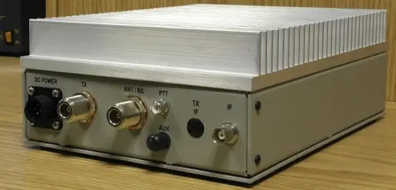
Start with good quality 50 ohm cables for the IF (28 MHz.) and REF (10 MHz.) connections. These connections are low level (25 watts or less) and are BNC connectors on the transverter. We find that simple RG-58 type BNC cables work fine with or without adapters to your HF transceiver. All transverters will require a PTT Line to enable the transmit mode of the transverter. The PTT input to the transverter is a RCA connector. This cable does not need to be shielded, but extra protection in a QRO station is a good idea. Many transceivers have RCA connectors for PTT outputs. But be sure to have whatever cable that is required ready to go. The DC power cable is supplied with the transverter and needs to be prepped and fuse-protected on the power supply end. The AUX connector will contain all sequencer connections and any other special customer requirements. The matching connector to the AUX connecter is supplied and should be wired before interfacing unless further testing of your system is required.
Connect your transceiver to the transverter: Interfacing the transverter to the transceiver is easy. After reviewing the front-page configuration and verifying that it is configured correctly for your purpose, begin cabling. An Important note: It is recommended that during the initial setup of the transverter, that it is not connected to your complete system with a HPA or mast mount LNA. All aspects of the transverter’s performance should be tested before a complete installation is made. Drive levels need to be established and proper switching needs to be verified before complete integration.
- Connect the DC POWER to the transverter with the supplied cable. 13.8 volts is optimum but the transverter will operate from 11 to 15 volts. Verify the DC power consumption of the transverter and use a power supply with some headroom. Cycle the power switch on the transverter and verify the “ON” light. Leave the transverter powered off.
- Connect an optional external 10MHz Reference to the 10MHz REF connector.
- Connect the IF cable(s). The transverter may have a common IF port or two separate ports, TXIF and RXIF, for the IF connections. The connector labeled “IF” is either the common port or the TXIF port depending on your requested configuration. Verify on the first page. The IF cable is either connected to a transverter port connector or the main Antenna connection of your transceiver. Refer to your manual.
- Connect the “Push-to-Talk” line out of your transceiver to the transverter. It is a RCA connector labeled PTT on the transverter. Refer to the configuration sheet for the type of keying required.
- If separate TX and RX ports were ordered, the internal transfer relay option has not been assembled. The separate ports are labeled RX and ANT/TX. If you have requested a common RF connection, the ANT/TX port has both TX and RX functions. Connect your antenna system or dummy load with a power meter to the appropriate RF connector on the transverter.
- On the bottom of the transverter, verify the TXIF and RXIF gain controls in the transverter. Turn the RXIF control fully clockwise and the TXIF control counter-clockwise. This is maximum attenuation on Transmit and minimum attenuation on Receive.
- Power your transceiver “ON”. If your transceiver cycles during power up, it may key the transverter. This is indicated by the Red “XMIT” light and the sound of relays cycling. Verify that the HF transceiver is in ”receive” and that the Red XMIT light is off on the transverter. If not, shut off your HF transceiver and check the PTT connection with the IF cables disconnected from the transverter. If both transceiver and transverter are in their receive modes, tune the transceiver to a frequency between 28.100 and 28.250 Mhz. Unless you ordered a “non-standard frequency” transverter and then depending on the conversion frequency, select an IF frequency in the middle of you operation range.
- Observe the noise level in the transceiver on the “S” meter and by ear. If it is too high, adjust the RXIF gain control in the transverter counter-clockwise until a slight noise increase is heard in the transceiver or just a slight movement in the “S” meter is detected. Power the transverter on and off to verify the change. The RXIF gain may be increased beyond this point, but it will start to degrade the dynamic range of your transceiver. It is all user preference. If you plan to use an external or mast mount LNA, this level will need to be re-adjusted. Find a signal on the band or use a signal generator to determine correct frequency, or minimum signal level.
- It is now recommended to test the transverter’s transmit section in the CW mode because most transceivers have carrier level or power level controls in this mode only. Do not use full or semi break-in if possible. Do not use FM, SSB or AM because it may not be possible to obtain maximum output power with a transceiver in these modes. Set the carrier/output power control to minimum or “0” output power (if you can). Place the transceiver into transmit. If the PTT circuit is connected correctly, the red “XMIT” light on the transverter will switch on. While observing the built in relative power meter or an inline RF power meter, slowly increase the carrier control (with key down) or increase the power output control to the maximum desirable IF drive level obtainable by your transceiver (maximum of 25 watts!) If this level is not what is indicated on the front page of this document, do not exceed that level. If you find that the transverter is not set-up for your transceiver’s range, please contact us.
- If the transverter is configured correctly for your transceiver, minimal power may be detected on the power meter. With the transceiver’s drive level at maximum specified for the transverter, slowly adjust the TXIF control in the transverter in a clockwise direction while observing the power meter. Set it to any desired level between 0 and the maximum specified output power. The relative power meter is set to show 9 bars lit for the specified maximum linear output power. This may vary with a bad VSWR but will be true into a 50 ohm dummy load. Switch the transceiver to USB and make a transmission. The power output and current drain should correlate to your speech pattern.
- You may re-adjust both RXIF and TXIF again if desired. The receive amplifier section and internal reference frequency should not need to be adjusted but you may if you wish.
- Basically, the transverter is ready to use and may be integrated into your system.
General Operation
If everything is adjusted correctly, general operation of the transverter should be transparent to the transceiver and the user. Except for the frequency read out, (if your transceiver doesn’t allow its display to be adjusted for transverter operation) it will be like operating on 10 Meters. All of the functions of the transceiver (filtering, DSP, split band operation, dual VFO) will be transposed to the frequency band of the transverter. Some cautions should be taken when operating CW or VOX. Operating the transverter in a “Full Break-in” mode is not recommended. Because of the mechanical relays in the transverter, there will be too much delay to operate “Full Break-in” effectively. AND—the relays would be abused if “Full Break-in“ is enabled. It is best to operate in “semi break-in” and adjust the delay of the PTT on your transceiver to match your comfortable CW operating speed in a way that the delay will hold the PTT until your transmission is complete. Since all transverters will be delivered with the sequencer enabled, this delay will need to be longer to allow all components within the system (Power amplifier, LNA, relays,) to complete their transition if utilized. If the stock transverter is to be used alone, the sequencer may be bypassed (see details below). This will shorten up the delay but will not allow “full break-in” without relay chatter The “ON” LED will be lit Green when the Frequency Synthesizer is locked to an optional external 10MHz Reference. This level should be between 0dBm to +13dBm. Otherwise, the synthesizer automatically switches to its on-board reference, and the “ON” LED will be Red.
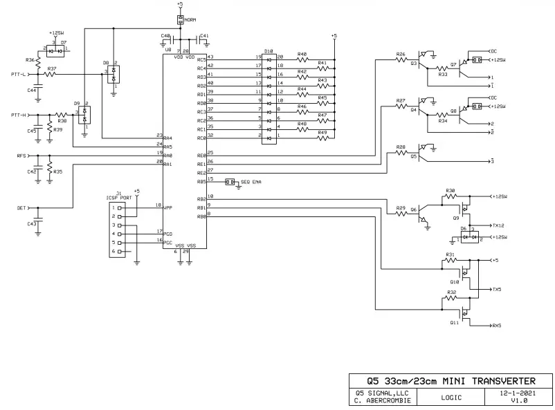
Sequencer: The sequencer connections are indicated on the front page and wired to the AUX connector. The reasoning is:
- Step 1 +12VDC on RX for a preamp @ 500 mA maximum
- Step 2 +12VDC on TX for a TR relay (around the preamp) @ 500 mA maximum
- Step 3 Ground on TX to key a power amplifier. Sinks 100 mA maximum
- Step 4 The transverter is keyed last
Other sequencer configurations are possible including the ability to switch higher voltages. Please contact Q5 SIGNAL for assistance. For mast mount LNA operation with the basic transverter or with an external high power amplifier, all tests should be done without RF applied. Verify that the switching is completed in your desired sequence and gradually add in external components as verified. The transverter’s sequencer may be bypassed to eliminate switching time delays but is only recommended if the transverter is to be used without any other system components such as LNAs or power amplifiers. This is accomplished by removing the solder bridge labeled SEQ ENA.
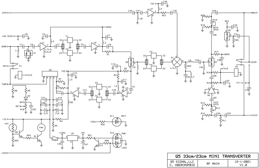
| C1 | 100pF 0805 | F1 | TAI-SAW TA1042A | R22 | 51R0 0805 |
| C2 | 100pF 0805 | F2 | TAI-SAW TA0536A | R23 | 51R0 0805 |
| C3 | 100pF 0805 | F3 | TAI-SAW TA1042A | R24 | 220R 0805 |
| C4 | 1nF 0805 | F4 | TAI-SAW TA0536A | R25 | 470R 0805 |
| C5 | 100pF 0805 | F5 | TAI-SAW TA1042A | R26 | 330R 0805 |
| C6 | 100pF 0805 | F6 | TAI-SAW TA0536A | R27 | 330R 0805 |
| C7 | 1nF 0805 | R28 | 330R 0805 | ||
| C8 | 1nF 0805 | FB1 | BLM21AG102SH1D | R29 | 330R 0805 |
| C9 | 100pF 0805 | FB2 | BLM18HE102SN1D | R30 | 10K0 0805 |
| C10 | 100pF 0805 | R31 | 10K0 0805 | ||
| C11 | 1nF 0805 | K1 | RG1ET-12V | R32 | 10K0 0805 |
| C12 | 1nF 0805 | K2 | G5Y-12V | R33 | 1K00 0805 |
| C13 | 100pF 0805 | R34 | 1K00 0805 | ||
| C14 | 100pF 0805 | L1 | CW201212-82NJ | R35 | 100K 0805 |
| C15 | 1nF 0805 | L2 | CW201212-82NJ | R36 | 1K00 0805 |
| C16 | 22uF TANT | L3 | CW201212-82NJ | R37 | 10K0 0805 |
| C17 | 100nF 0805 | L4 | CW201212-82NJ | R38 | 10K0 0805 |
| C18 | 100pF 0805 | L5 | CW201212-82NJ | R39 | 10K0 0805 |
| C19 | 22uF TANT | L6 | CW201212-R33J | R40 | 330R 0805 |
| C20 | 100nF 0805 | L7 | CW201212-R33J | R41 | 330R 0805 |
| C21 | 100pF 0805 | L8 | CW201212-82NJ | R42 | 330R 0805 |
| C22 | 1nF 0805 | L9 | CW201212-82NJ | R43 | 330R 0805 |
| C23 | 1nF 0805 | L10 | N/A | R44 | 330R 0805 |
| C24 | 1nF 0805 | R45 | 330R 0805 | ||
| C25 | 1nF 0805 | M1 | SYM-18H+ | R46 | 330R 0805 |
| C26 | 1nF 0805 | R47 | 330R 0805 | ||
| C27 | 1nF 0805 | Q1 | MJD31C | R48 | 330R 0805 |
| C28 | 1nF 0805 | Q2 | MMBT4401 | R49 | 330R 0805 |
| C29 | 1nF 0805 | Q3 | MMBT4401 | R50 | 1K00 0805 |
| C30 | 1nF 0805 | Q4 | MMBT4401 | R51 | 330R 0805 |
| C31 | 10pF 0805 | Q5 | MMBT4401 | R52 | 330R 0805 |
| C32 | 1nF 0805 | Q6 | MMBT4401 | ||
| C33 | 1nF 0805 | Q7 | MJD32C | U1 | TQP3M9037 |
| C34 | 100pF 0805 | Q8 | MJD32C | U2 | TQP3M9008 |
| C35 | 100pF 0805 | Q9 | DMP3099L | U3 | ERA-2SM+ |
| C36 | 100pF 0805 | Q10 | DMP3099L | U4 | GVA-60+ |
| C37 | 100pF 0805 | Q11 | DMP3099L | U5 | RA18H1213G |
| C38 | 1nF 0805 | Q12 | MMBT4401 | U6 | MAR-6SM+ |
| C39 | 100pF 0805 | U7 | GVA-60+ | ||
| C40 | 100nF 0805 | R1 | 470R 0805 | U8 | PIC18F43K22-I/PT |
| C41 | 100nF 0805 | R2 | 470R 0805 | U9 | MC7805 |
| C42 | 1nF 0805 | R3 | 39R0 0805 | ||
| C43 | 1nF 0805 | R4 | 51R0 0805 | ||
| C44 | 1nF 0805 | R5 | 470R 0805 | ||
| C45 | 1nF 0805 | R6 | 470R 0805 | ||
| C46 | 100nF 0805 | R7 | 1K00 0805 | ||
| C47 | 4.7uF TANT | R8 | 51R0 0805 | ||
| R9 | 100R 0805 | ||||
| D1 | BAR66 | R10 | 1K POT | ||
| D2 | BAR64-05 | R11 | 50 OHM LOAD | ||
| D3 | BAS70-04 | R12 | 220R 0805 | ||
| D4 | BAR64-05 | R13 | 1K POT | ||
| D5 | BAS70-04 | R14 | 220R 0805 | ||
| D6 | BAT54S | R15 | 470R 0805 | ||
| D7 | BAT54S | R16 | 470R 0805 | ||
| D8 | BAT54S | R17 | 470R 0805 | ||
| D9 | BAT54S | R18 | 220R 0805 | ||
| D10 | SSA-LXH1025ID | R19 | 1K POT | ||
| D11 | WP710A10ID | R20 | 220R 0805 | ||
| D12 | WP115WEGW | R21 | 100K 0805 | ||