
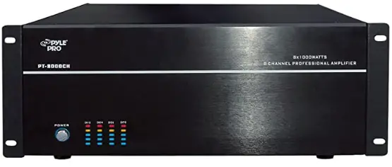
 Pyle PT8000CH 8-Channel 8000-Watt Stereo
FEATURES
- Audiophile Design
Sophisticated design and superior internal components result in outstanding sound quality, performance, and long-term reliability. - Advanced Protection
Each channel is individually protected. If the circuitry determines that a channel must be shut down for protection, a rare occurrence, only the channel affected will be turned off. The other channels will continue to play. Once conditions return to normal, the affected channel will be turned back on and operate as normal. - Flexible Input Selection
Each of the 8 channels can be assigned a variety of source inputs. Dedicated input can be assigned to each channel. Each channel can also be configured to play common signals from the Bus or Auxiliary inputs. This provides the flexibility needed in sophisticated custom audio installations. - Bridging
The power output of adjacent channels can be combined to provide extra power when needed in certain areas. This is easily accomplished by flipping a single switch. - Individual Channel Level Adjustments
Each channel has its own level adjustment. This allows the loudness of each speaker to be perfectly matched to its area.
Diagram 1-Front Panel
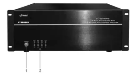
- POWER SWITCH
Master power switch. Turns off power to amplifier and Power Mode Circuitry. - POWER OUTPUT LEVEL INDICATOR
This is a level meter that shows outputs levels of ch 1-2 ch 3-4 ch 5-6 & ch 7-8 conditions on the operation. Therefore, you can see the output condition thru this master indicator.
Diagram 2- Rear Panel
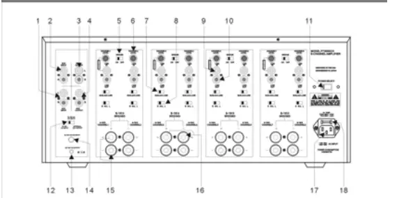
- 1-2. Main bus inputs low outputs from receivers, and co-players. TVs, or any stereo audio sources to be amplified across all channels for easy multi-room applications. Auxiliary inputs allow an additional audio source to be played on any channel that is switched to AUX.
- 3-4. Bus outputs allow the bus inputs to be sent to other amplifiers or a daisy chain without the need for Y cable splitters. Auxiliary outputs allow you to daisy chain the input to other audio sources.
- A bridging switch allows you to easily double the power output by coupling two channels together
- Level controls for each channel.
- The input Selection switch allows you to select between the common bus and auxiliary inputs, or the individual channel input.
- One switch allows you to select which stereo input channel will play through the speaker out- puts: left, right, or left and right combined. switched to Let * Right, both input channels are
- Gold-plated individual channel inputs allow you to connect different audio sources to each hann
- Line signal output
- Voltage Selector 110-220V
- 12-15VACIDC input/ internal DC12V output selector.
- DC 12V 1A output
- 12-15AC/DC input jack.
- Speaker channel output binding posts.
- 5peaker channel bridged mode binding.
- 3-Prong removable power plug.
- Fused AC.
SYSTEM DESIGN & OPERATION CONSIDERATIONS
To best understand system design and operation of the PT8O00CH t is useful to understand the following terms and features as they relate to the PT8000CH.
- Multi-Room
A system design that plays the same source at the same time in all rooms. If a change is made in one room, the same change takes place in all other rooms. For example. if the listener changes from co to Tuner in the bedroom. the same change will be heard in the kitchen. Note: With the use of volume controls or speaker switchers the volume of each room can be controlled separately of the other rooms. - Multi-Zone
A system design that allows different sources to be played in each room. A change in one room can be made without changing the other rooms. For example, the CD player can be heard in the bedroom while the kitchen is playing the tuner. - Bridging
combining of 2 channels to create one mono channel. It is useful when more volume is needed in a particular area - Source
Component, audio or video, that provides an audio signal. Examples are CDs,. VCR, DVD, tape deck, and tuner. The source provides the audio information that is amplified by the PTBO0OCH - Channel
A distinct unit of the amplifier provides output to one speaker. The PTBO0OCH the input to each channel can be configured to select from the BUs INPUT, the AUX INPUT or that channel’s unique CHANNEL INPUT. Two adjacent channels can be bridged to provide higher power to one speaker. - Level Controls
Allow any of the channels to be adjusted independently to raise or lower the output of each channel. This may be used to control the speaker output in order to balance different rooms or areas of the system. - BUS’AUX°LINE Switch
Allows each channel to play a variety of different inputs. Depending on the switch position the channel amplifies the signal connected to the BUS input, the AUX input, or its own LINE input. - RR+LLSwitch
When either a BUS aux input is selected, this switch is used to direct the channel to play the left signal from the input L” or the right signal from t input Ror a combined right and left signal from the input “R+L.
SYSTEM DESIGN & OPERATION CONSIDERATIONS
Bus Input
Allows the signal from a source to be distributed to any of the 12 channels on the amplifier.
Auxiliary Inputs
Allows the signal from a secondary source to be distributed to any of the 12 channels oT the amplifier. Diaaram 3: 12-15V AC/DC selector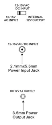
SYSTEM DESIGN EXAMPLES
There are many ways to configure the PT8000CH amplifier. The following pages contain some typical installation examples. Use these examples to generate ideas for your system design.
- Multi-Room Installation Example (Diagram 4)
This illustrates the simplest use of the PT8O0OCH, distributing audio throughout the home. In this example, only one source can be selected at a time, and all pairs of speakers have the same audio signal available The input Selection switch is set to “BUS on all channels. Adjacent channels are assigned left and right. - Multi-Zone Example #1 (Diagram 5)
This illustrates the simplest way to provide an audio signal to an area that is independent of the main audio signal. Zone 2 uses a CD player connected to just that Zone. The rest of the system operates Zone 1 and is connected to the preamplifier/receiver The input Selection switch on channels 1-10 is set to “BUS with adjacent channels assigned left and right. The Input Selection Switch on channels 11 and 12 is set to LINE - Multi-Zone Example #2 (Diagram 6)
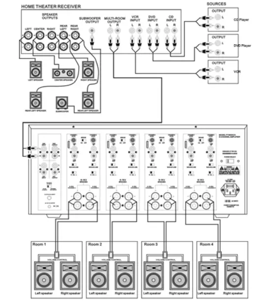
This illustrates the ability to listen to different audio signals in each zone, independent of every other zone. The system relies on a multi-zone preamplifier or up to 6independent preamplifiers The input Selection switch on each channel is set to “LINE. - Home Theater / Multi-Room Example (Diagram 7)
This configuration allows the user to access the sources connected to a home theater receiver for use in a multi-room installation. It relies on the home the- ater receiver having a muilti-room or similar output The input Selection switch on each channel is set to “BUS with adjacent channels assigned light and light.
Diagram 4- Multi-Room Installation Diagram 5- Multi-Zone Installation # 1
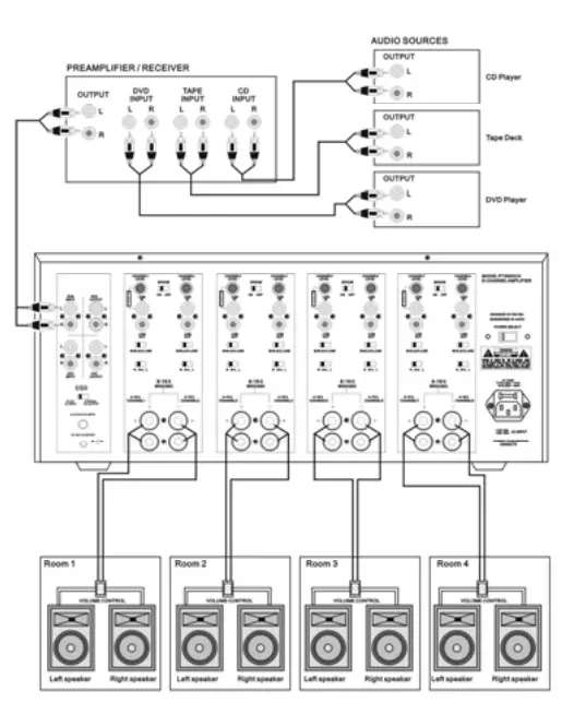 Diagram 5- Multi-Zone Installation # 1
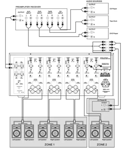
Diagram 6- Multi-Zone Installation #2
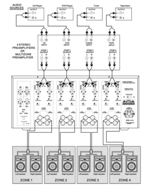
Diagram 7- Home Theater/Multi-Room Installation
INSTALLATION CONSIDERATIONS
DO
Place the amplifier with the feet resting on a solid flat level surface Place the amplifier in a well-vented area to provide proper cooling. In areas that iack proper ventilation, such as tight cabinets or racks, it may be necessary to install smal fans to create air movement
DO NOT
Don’t block the ventilation holes on the top or bottom of the amplifier Never place it on carpeting or similar material Don’t place the amplifier in any other position other than horizontal with the feet down. Never place on its side or rest on the back where the terminals are located. Don’t the amplifier near heat sources, or in an area that it would b exposed to moisture.
YOU SHOULD KNOW
The power supply is very large and therefore may cause a hum to be heard in some components if they are placed very close to the amplifier.
INSTALLATION
Selecting inputs (See Diagrams 8 &9)
Each channel is capable of delivering the source from many inputs. The three main inputs are BUS, AUX and LINEIN. The selection for these inputs is done via the Input Selection switch, marked BUS-AUX-LINE.To select a source for each channel, follow the steps below.
- Select the desired source input. Set the Input Selection switch to BUSiwi to play source connected to the BUSINPUT), AUX (will play source connected- ed to the AUx INPUT) or LINE (will play source connected to the LINE IN).

- The BUS and AUX inputs each have a left and right input. The left, right or combined left and right signal from these may be selected via the switch marked R R+LL” . Select the side you want the channel to deliver Selecting “R” t will play the right channel of the selected input. Selecting “L will play the left channel of the selected input. Selecting R+L will play the combined signals of right and left.


Selecting Bridge Mode (See Diagram 11)
Under normal operation, this should be left in the 8 ohm position as illustrated in Diagram 10. It is sometimes desirable to combine two channels into one through bridging. The output of the combined channels can then be used to power one speaker. To bridge two adjacent channels first make sure that the lmpedance Switch is in the 8ohm position. Next move the switch markedBRIDGE to the ON” position. The speaker must be connected to the terminals immediately under the BRIDGED” text as indicated in Diagram 11. All input selection and settings for the bridged channels will be done on the channel to the left. Do not connect more than one speaker to the outputs of the bridged channel.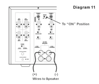
Control Output
The 12V output jack on the back of the amplifier can be used to turn on a variety of components equipped to be activated when they receive a 12V DCc output. Voltage is only delivered to the jack when the amplifier is “on” or active. When the amplifier turns off, the voltage ceases. Before connecting another device to the 12 output please make sure that the device can accept 12V DC at 1A. To connect the output to another device you must access the output jack with a two-conductor plug that fits into the 3.5mm jack. Be aware that the tip of the plug will be (). If you are unsure about using this feature please contact an authorized PYLE dealer for assistance
Connecting the Speaker Wire
CAUTION: Only make connections when the amplifier is turned off.
Using Standard Connections (See Diagram 12)
For best performance use high quality speaker cables. The banana plug outputs on the back of the amplifier allow for a variety of ways to connect your speakers to the amplifier.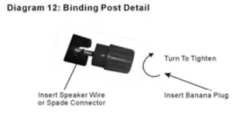
Connecting the Line Level Audio Inputs
CAUTION: Only make connections when the amplifier is turned off. There are three areas where an input signal can be connected, BUs, AUX, and LINE IN. Refer to the System Design Examples to determine which is best suit ed for your application.
Audio Outputs
Sources connected to the BUS or “AUX inputs can be forwarded to other components or amplifiers by connecting to the corresponding output sections to the right of each input section. By using standard audio patch cables, you can connect these outputs to the inputs of another amplifier. Up to 5 SpeakerCraft amplifiers can be daisy-chained together.
AC Power
Plug the socket of the AC cord supplied with the amplifier into the receptacle on the rear of the amplifier. Plug the 2-prong plug directly into a 110v 60 Hz wall outlet
CAUTION: Do not plug the amplifier into the preamplifier or receiver’s switched outlet. If you wish to have the amplifier turn on once the preamplifier or receiver is activated, use one of the turn-on modes, voltage or audio.
OPERATION
See Diagram 1 for the location of the following:
- Active LED
When lit, the Active LED indicates that the amplifier is operating. Refer to the Power Mode Selection section of this manual for further information - Level Adjustment Knobs
The level adjustment knobs on the back panel of the amplifier can be used to adjust the level of each channel. There are many reasons for needing to adjust the level. You many wish to closely match other levels in the system, or you may wish to limit the volume level in an area, such as a child’s room.
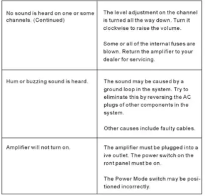
TROUBLESHOOTING
The amplifier is designed to function trouble-free. Most problems occur be shooting list first. If the problem persists, contact your authorized 0poang errors. it you have a problem please check the trou- PYLE Customer service at (718)535-1800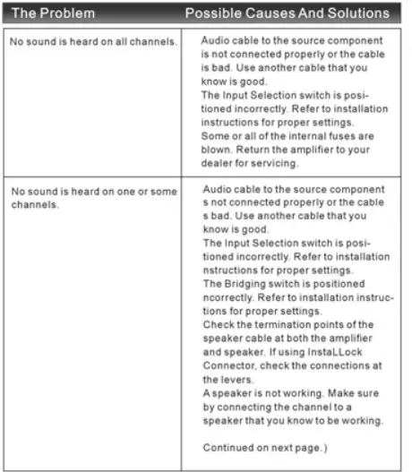
SPECIFICATIONS
Features
- Peak Power:1000Wx8
- Three Color (L.E.D) Output Level Indicator
- Bridgeable Amplifier
- Independent Level Controls for Each Channel
- Each Channel Can Be Set to Left, Right, or Mono of the Bus,
- Aux Inputs or its Own Dedicated Input
- Adjoining Channels are Bridgeable
- Separate Protection Circuitry for Each Channel Pair
- 12V Control Output for Switching Auxiliary Devices On and Off
- Pass-Through Output Allows Daisy-Chaining of Multiple Amplifiers
- 5-Way Binding Posts
- 4U High
- Dimensions: 19 X 19.3″d x 7.1″h
- Weight: 48.5 lbs
FAQS
sometimes because we have listing conflicts we change the model number one or two digits. Specs and other features of the unit are the same.
The booklet says 50 watts per channel RMS at 8 ohms.
our sincere apologies for the inconvenience. We have dedicated Technical Support who can help you out with your concern. Please call 718 535 1800 Press 2 then 1 from Monday to Friday from 9 AM to 5 PM EST.
it is an amplifier where you can connect your TV, DVD, and other devices. It is like binding all devices in 1 unit. For more info, kindly visit our website pyleaudio.com. Type the model number on the search box PT6000CH.
yes it comes with remote control. For more info, kindly visit our website pyleaudio.com. Type the model number on the search box PT6000CH.
No
This model power is RMS:100 with 8 channels, which means each channel max can play 100w (8ohm)
We have checked your unit specification and it looks like that all outputs for speakers are provided on the amp. The external amp would only be for additional power and speaker
The RMS Watts for PT8000CH is 200W x 8-Ch @ 4Ohm
Yes it can. It normal practice to use a graphic EQ for your monitors.
This unit’s voltage selector range from 110 v to 220 volts.
The volume controls are located on the back. I use this unit as an amplifier for speakers throughout my house, each channel goes to a wall volume control knob first, then to speaker. I would highly recommend adjusting the channel control knobs on back of amp to limit the output to wall unit or the amp will burn them up. Go ahead and get 100 watt wall units if this is what you want to use it for.
There is 1000 Watts per channel. 8000(total watts) divided by 8(channels) = 1000
Unfortunately, this manufacturer has chosen not to publish this and other specifications.
Just about anything from ceiling-mounted multi zone systems to drive high power requirement loads such as large subwoofers or transducer arrays in home theater applications.


