 BRADFORD WHITE RTGS199N1 Tankless Heater
Safety Regulations
Safety Symbols
WARNING
Warnings in this document are identified by a warning triangle printed against a grey background. Keywords at the start of a warning indicate the type and seriousness of the ensuing risk if measures to prevent the risk are not taken.
For safety symbols, ‘DANGER’, ‘WARNING’, CAUTION’ are indicated and the definitions for these terms are as follows:
- DANGER
Indicates an imminently hazardous situation which, if not avoided, will result in death or serious injury. This signal word is limited to the most extreme situations. - WARNING
Indicates a potentially hazardous situation which, if not avoided, could result in death or serious injury. - CAUTION
Indicates a potentially hazardous situation which, if not avoided, may result in minor or moderate injury. It is also used to alert against unsafe practices and hazards involving only property damage.
Safety
PLEASE READ SAFETY PRECAUTIONS BEFORE INSTALLATION.
WARNING
These instructions are intended as an aid to professional service personnel for proper installation, adjustment and operation of this unit. Read all instructions prior to attempting installation or operation. Failure to comply with instructions can result in improper installation, adjustment, and possibly result in fire, electrical shock, property damage, personal injury or death.
WARNING
Disconnect all power to the unit before starting any service or maintenance. Failure to do so could cause severe electrical shock resulting in personal injury or death.
Introduction
This Manual is used to present some of the most common applications for the appliance. Drawings are shown with both piping and corresponding electrical connections where applicable. Field supplied equipment shown in this manual does not represent any one manufacturer or specific model. This manual does not cover all potential installation practices and piping techniques possible when installing water heating appliances. It is the responsibility of the professional installer to determine the best solution for the application, as well as abide by local building codes.
NOTICE
In this manual concept drawings are used to show common applications, and do not cover all safety, design, or installation considerations. Additional safety and/or auxiliary equipment may be needed. Reference concept drawings are for use by officials, designers and professional installers. Installers must have adequate knowledge of best industry practices, procedures, and applications involved. It is the responsibility of the professional installer to ensure that the installation abides with local building codes.
This manual covers the most common system application however it is not the intention of this manual to cover all potential applications as possibilities are nearly endless. If an application is not covered within this manual and questions surrounding best practices arise please contact the manufacturer with specific application needs.
This manual is not to be used in place of the installation and operation manuals included with the appliance. For a copy of the applicable Installation and operation materials a copy can be downloaded from the manufacturer’s website. All manuals/specifications are subject to change.
NOTICE
Installation must conform with local codes or, in the absence of local codes, the National Fuel Gas Code ANSI Z223.1/NFPA 54.
In Canada: Installation must conform with CGA B149.(1,2) INSTALLATION CODES and/ or local installation codes.
Water Heater Sizing and Specifications
This section describes sizing rules for the RTGS and RTGR series water heaters from
Bradford White Corporation and provides a general overview to the specification sheets and model. More detailed information is contained in the installation manuals.
Download manuals at www.bradfordwhite.com
Sizing for specific application or loads
Peak Demand Sizing by Flow rate x Rise
The peak demand is the product of the flow rate and rise. Flow rate is the number of gallons per minute being demanded. the Rise is the difference between the demanded setpoint and the inlet temperature. If inlet temperature and inlet temperature cannot be determined refer to the fixture count method.
Determining Peak Demand Flow:
- Determine which fixtures will be used simultaneously. The total flow rate is the peak demanded flow. Determine the flow rate of each of these fixtures and total them.
- To determine flow rate determine the length of time required to fill a known volume. Using the fill time and the container volume and the equation below calculate peak flow rate. (example: 20 seconds to fill 1 gallon container = 3 GPM)


Counting Fixtures to determine Peak Demand Flow:
- Each Sink will flow ~1 GPM.
- Each Shower will flow ~ 2 GPM.
- Each Bath/Garden tub will flow 3.5-4.5 GPM
- Total all simultaneous flow rates for peak demand flow.
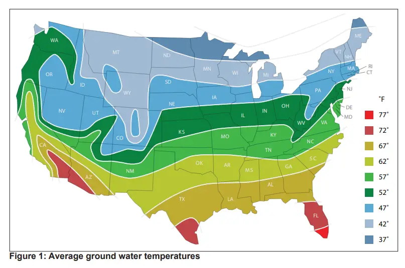
Determining Rise:
- Using a thermometer run a cold water fixture until the room temperature water is purged from the cold water line. Rise is the difference between the demanded setpoint and this cold water temperature. For example if inlet water is 58°F and setpoint is 120°F the rise is 62°F. If supply water temperature cannot be measured refer to the chart on the next page for general ground water temperatures.
Example Peak BTU Demand Calculation:
- Peak Flow is two showers and one sink, 2+2+1 = 5 GPM.
- Supply is 58°F and Setpoint is 120°F, 120°F – 58°F = 62°F
- Peak BTU demand = 525 * 62(°F) * 5(GPM) = 162,750 BTU / hr.


Specifications
| Model Name | RTGS199N1 / RTGS199X1 | RTGR199N1 / RTGR199X | |||
| Gas Input Rate | MAX | 199,000 Btu/h | |||
| MIN | 18,000 Btu/h | ||||
| High Elevation | 180,000 Btu/h | ||||
| Hot Water Capacity | 35°F Rise | 11.1 Gal/min (42 L/min) | |||
| 45°F Rise | 8.7 Gal/min (32.9 L/min) | ||||
| 77°F Rise | 5.1 Gal/min (19.3 (L/min) | ||||
| Installation | Indoor / Outdoor Wall Hung (with outdoor vent cap) | ||||
| Flue System | Sealed Combustion Direct Vent, Single Vent, Outdoor | ||||
| Max Vent Run | 2” (60ft) / 3” (150ft) Schedule 40 PVC, CPVC, PP | ||||
| Orifice Size | NG (Gas / Needle) | 0.330” (8.4mm) / 0.342” (8.7mm) | |||
| LP (Gas / Needle) | 0.259” (6.6mm) / 0.263” (6.7mm) | ||||
| Gas Supply Pressure | NG | 3.5” WC to 10.5” WC | |||
| LP | 8.0” WC to 14” WC | ||||
|
Manifold Pressure | Gas Type | NG | LP | ||
| Low Fire | 2″ VENT | 0.1˝ WC | -0.05˝ WC | ||
| 3″ VENT | 0.1˝ WC | -0.05˝ WC | |||
| High Fire | 2″ VENT | -0.20˝ WC | -0.30˝ WC | ||
| 3″ VENT | -0.20˝ WC | -0.30˝ WC | |||
| Power Supply | Main Supply | 120V 60Hz | |||
| Max Current | Less than 2A | ||||
| Power Consumption | Standby | 2.7W 2.7W | |||
| Operation | 74W / 188W with external pump | 188W with Internal Pump | |||
| Anti Freeze | 53W | 117W | |||
| Ignition System | Direct Electronic Ignition / Automatic Flame Sensing | ||||
| Burner System | Premixed Metal Fiber Burner | ||||
| Gas Valve System | Air Ratio Valve | ||||
| Minimum Flow Activation Flow | 0.5 GPM | ||||
| Internal Pipe Material | STS 304, Stainless Steel with PPS | ||||
| Dimensions | W 17.3″ – H 27.6″ – D 14.9″ | ||||
| Weight | 78 lbs(35.5 kgs) | 85 lbs(38.5 kgs) | |||
| Water Holding Capacity | Under 2 Gallons | ||||
| Control Panel / Circuit Board | PR-922C / NGTH-9600C | PR-952C / NGTH-9600C | |||
| Water Pressure | MAX | 150 psi | |||
| MIN | 15 psi | ||||
| Materials | Casing | Cold Rolled Carbon Steel | |||
| Heat Exchanger | Heat Exchanger : SS 304 | ||||
| Safety Devices | Flame Sensor, Overheat Cut Off Switch , Gas Leak Detector, Water Leak Detector, Exhaust Temperature Sensor, Water Temperature Sensor | ||||
Temperature
- Operating ambient Temperature Range : Range: 14°F to 140°F (-10 to 60°C).
- Operating Relative Humidity up to: 90% at 104°F (40°C).
- Shipping & Storage Temperature Range of : -4°F to 176°F (-20 to 80°C).
Dimensions
RTGR199N1 / RTGR199X1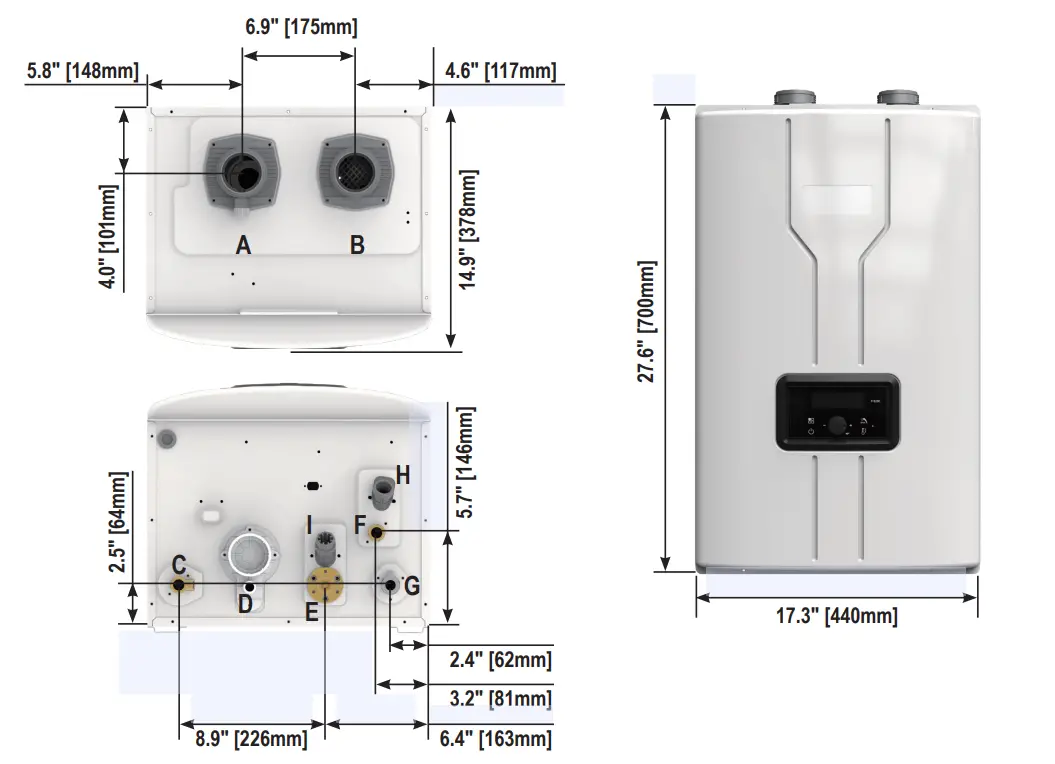
|
| Description | Size |
| A | Exhaust | 2″ PVC |
| B | Air Intake | 2″ PVC |
| C | Hot Water | 3/4″ NPT |
| D | Condensate | 1/2″ NPT |
| E | Recirculation Return Connection | 3/4″ NPT |
| F | Cold Water Connection | 3/4″ NPT |
| G | Gas | 3/4″ NPT |
| H | Cold Water Filter | – |
| I | Recirculation Return Filter | – |
Dimensions: RTGS199N1 / RTGS199X1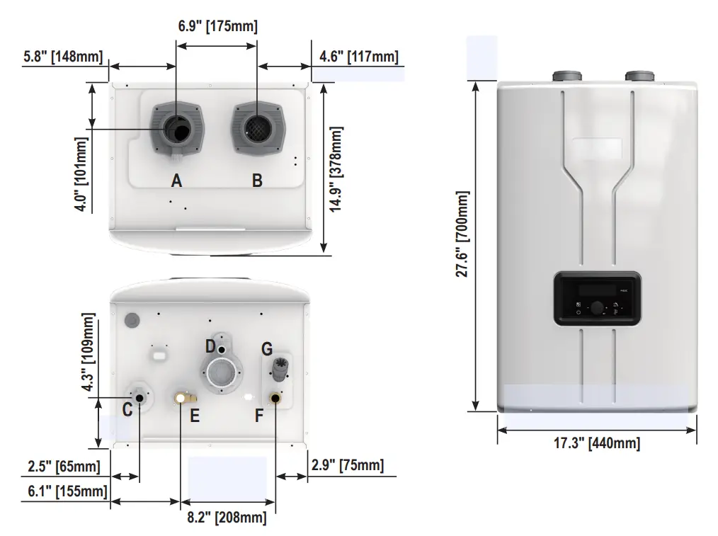
| Description | Size | |
| A | Exhaust | 2″ PVC |
| B | Air Intake | 2″ PVC |
| C | Gas | 3/4″ NPT |
| D | Condensate | 1/2″ NPT |
| E | Hot Water Connection | 3/4″ NPT |
| F | Cold Water Connection | 3/4″ NPT |
| G | Cold Water Filter | – |
Components
Name of Components: RTGS199N1 / RTGS199X1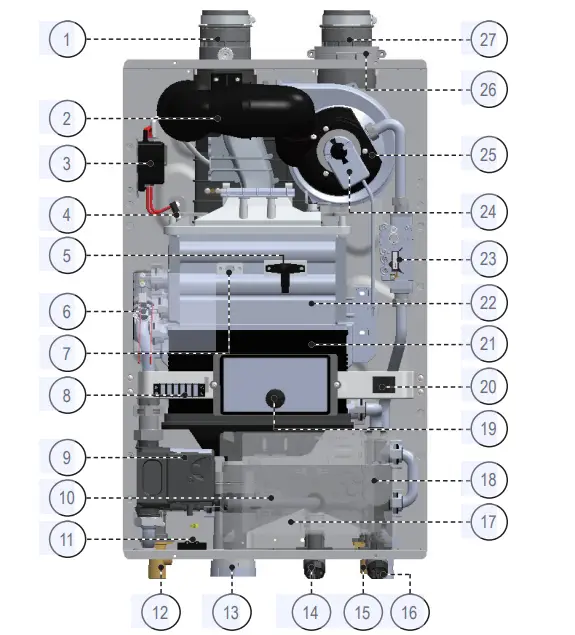
| # | Name of Component |
| 1 | Vent Pipe Collar |
| 2 | Combustion Air Intake Assembly |
| 3 | Ignition Transformer |
| 4 | Igniter |
| 5 | Flame Detection Sensor |
| 6 | High Limit Switch |
| 7 | Sight Glass |
| 8 | Terminal Port |
| 9 | Circulation Water Pump |
| 10 | Mixing Valve |
| 11 | Water Leak Detector |
| 12 | Domestic Hot Water (DHW) Outlet |
| 13 | Condensate Trap Cleanout |
| 14 | Recirculation Return Water Connector |
| # | Name of Component |
| 15 | Cold Water Inlet |
| 16 | Gas Inlet |
| 17 | Main Controller |
| 18 | Water Adjustment Valve |
| 19 | Control Panel |
| 20 | Manual Power Switch |
| 21 | Secondary Heat Exchanger |
| 22 | Primary Heat Exchanger |
| 23 | Gas Valve |
| 24 | Air Gas Mixture (AGM) Actuator |
| 25 | Blower |
| 26 | Air Intake Filter |
| 27 | Air Intake Collar |
▪ Name of Components: RTGS199N1 / RTGS199X1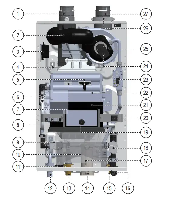
| # | Name of Component |
| 1 | Vent Pipe Collar |
| 2 | Combustion Air Intake Assembly |
| 3 | Ignition Transformer |
| 4 | Igniter |
| 5 | Flame Detection Sensor |
| 6 | High Limit Switch |
| 7 | Sight Glass |
| 8 | Terminal Port |
| 9 | Water Mixing Valve |
| 10 | Main Controller |
| 11 | Water Leak Detector |
| 12 | Gas Inlet |
| 13 | Domestic Hot Water (DHW) Outlet |
| 14 | Condensate Trap Cleanout |
| # | Name of Component |
| 15 | Cold Water Inlet |
| 16 | Cold Water Filter |
| 17 | Condensate Trap |
| 18 | Water Adjustment Valve |
| 19 | Control Panel |
| 20 | Manual Power Switch |
| 21 | Secondary Heat Exchanger |
| 22 | Primary Heat Exchanger |
| 23 | Gas Valve |
| 24 | Air Gas Mixture (AGM) Actuator |
| 25 | Blower |
| 26 | Air Intake Filter |
| 27 | Air Intake Collar |
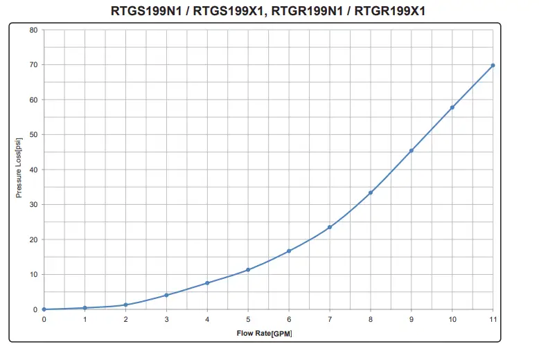
Water Heater Sizing
- Pressure Drop of Appliance
RTGS199N1 / RTGS199X1, RTGR199N1 / RTGR199X1
- Pressure Curve of Internal Pump(if applicable)
 Equivalent Power Pumps to RTGR Internal pump:
- taco 008
- Grundfos UP15-55
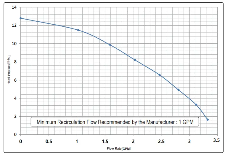 Equivalent Power Pumps to RTGR Internal pump:
Single Unit Applications
Water Heater Modes (RTGR199N1, RTGR199X1)
Applications shown in this section are for single appliances. If cascading is required refer to Section 5 Multiple Unit Installations.
|
Mode |
Description | Setting | Requirement | Performance | |||
| 11:RC | Dedicated Return Line | Accessory | Wait Time Water Savings | Energy Savings | Hot Water Temperature | ||
| oFF No Recirculation | Recirculation Pump remains Idle. | OFF | No | – | – | – | – |
| Itnl Internal | Hot water circulates within the appliance, No return line needed. | Itnl | No | – | Better | Better | Better |
| Etnl External | Hot water circulates within the house using external return line. | Etnl | Yes | – | Best | Better | Best |
| tt24 title 24 | External recirculation when demand button is pressed. | tt24 | Yes | O | Better | Best | Best |
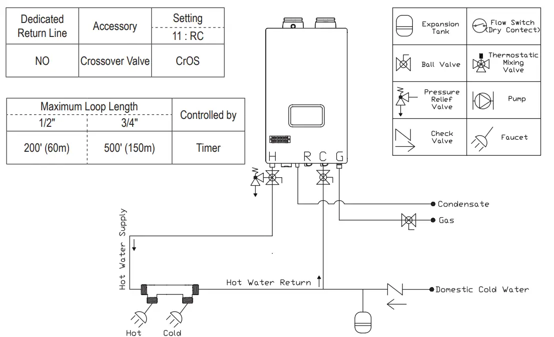
| CrOS Crossover Valve | Hot water circulates within the house using 3rd party bypass valve. | CrOS | No | O | Best | Good | Warm |
* Recirculation is activated by Timer [Auto / Manual]
Recirculation timer setting can be changed by customer’s own desire time.
Auto (self learning mode) function can be selected by customer’s need.
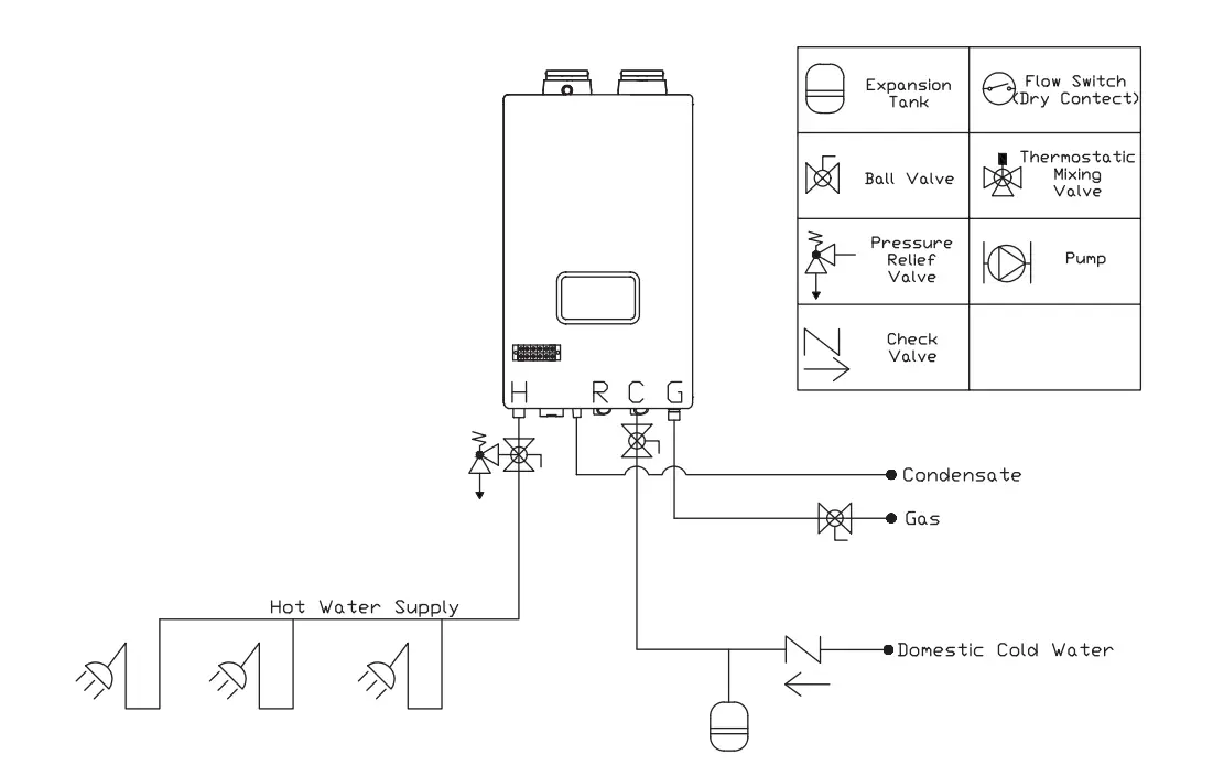
No Recirculation Mode, Internal Recirculation Mode
- Only POTABLE water may be plumbed through the water heater.
- The water heater cannot be used for space heating application
- Expansion tank is required if a backflow preventer is installed

Recirculation Mode [ External Mode]
- Provides most comfortable option. Maintains consistent hot water availability during specified times
- Timer can be manually customized or programmed to automatically learn daily usage patterns.
- Ability to optimize by using Installer Mode function 3: RT to adjust loop temperature for maximum comfort and safety.

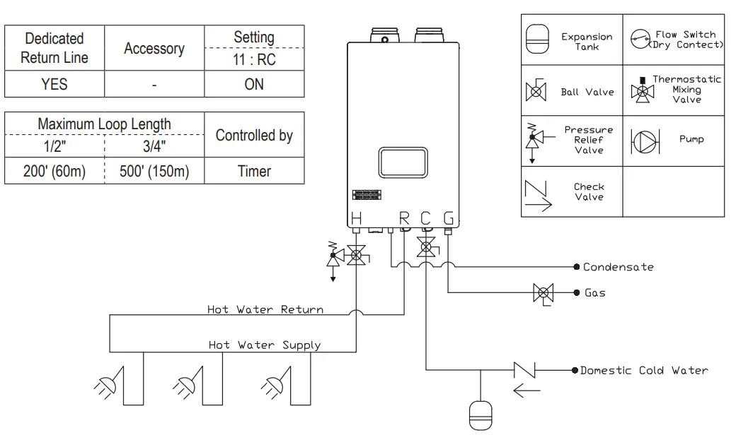
The recirculation return pipe must be installed in the field in order to apply the ‘External Mode’.
This mode allows the hot water pipes to be warmed up and also serves as the freeze protection function.
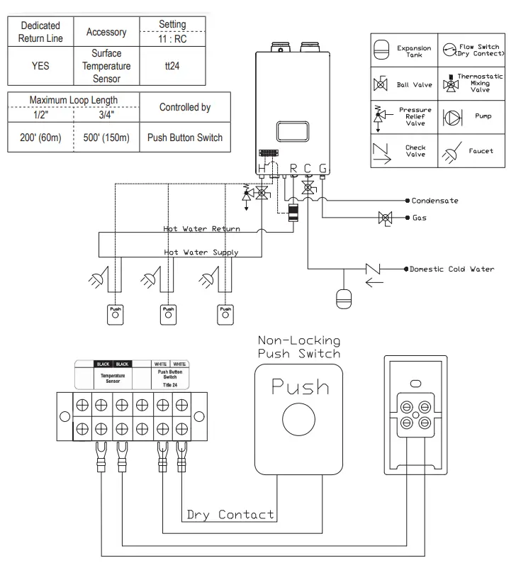
Recirculation Mode
On Demand(tt24) Mode
- Provides best energy savings option with recirculation.
- Designed to meet California Title 24 requirements.
- Recirculation will only operate after the push button switch is pressed. Hot water will not be available immediately.
- Built-in timer function is disabled.
- Circulation pump will start on-demand to purge cold water from the water lines and replace with hot water.
- Pump will stop operating once hot water has successfully reached 102°F at the installed temperature sensor.
- Do not repeatedly press on-demand button. Title 24 function will not operate again until the water at the return is cool.

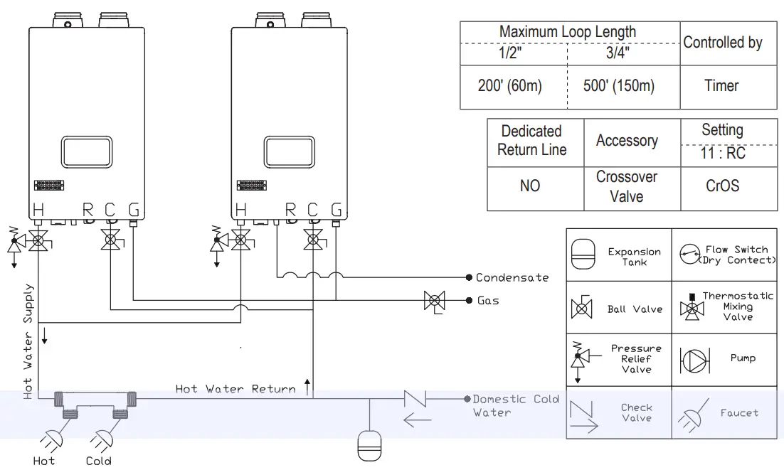
Crossover(CrOS) Mode]
- Provides recirculation option for homes without a dedicated return line by utilizing the cold water line as a return line.
- Timer can be manually customized or programmed to automatically learn daily usage patterns.
- In order to prevent hot water from being supplied into the cold water line, the thermal element in the crossover valve will close at about 95°F. As a result, hot water may not be available at all times (only warm water).

Water Heater Mode (RTGS199N1, RTGS199X1)
| Mode | Description | Setting | Requirement | Performance | |||
| 11:RC | Dedicated Return Line | Accessory | Wait Time Water Savings | Energy Savings | Hot Water Temperature | ||
| No Recirculation | Heat water as draws occur, no recirculation occurs | OFF | No | – | – | – | – |
| Pulse* | Unit controls an External pump with a dedicated return | PuLS | No | – | Best | Better | Best |
| TT24* (Title24) | Only operates recirculation line with a push of a button. | tt24 | No | O | Better | Best | Warm |
| On Demand* | Only operates recirculation line with a push of a button. | OndE | No | O | Better | Good | Best |
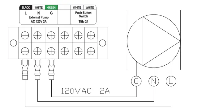
*Models not equipt with a built-in pump will require a field supplied circulator to be installed for use with recirculation modes, See section 3.6 Water Heater Sizing for pressure curves for circulator sizing.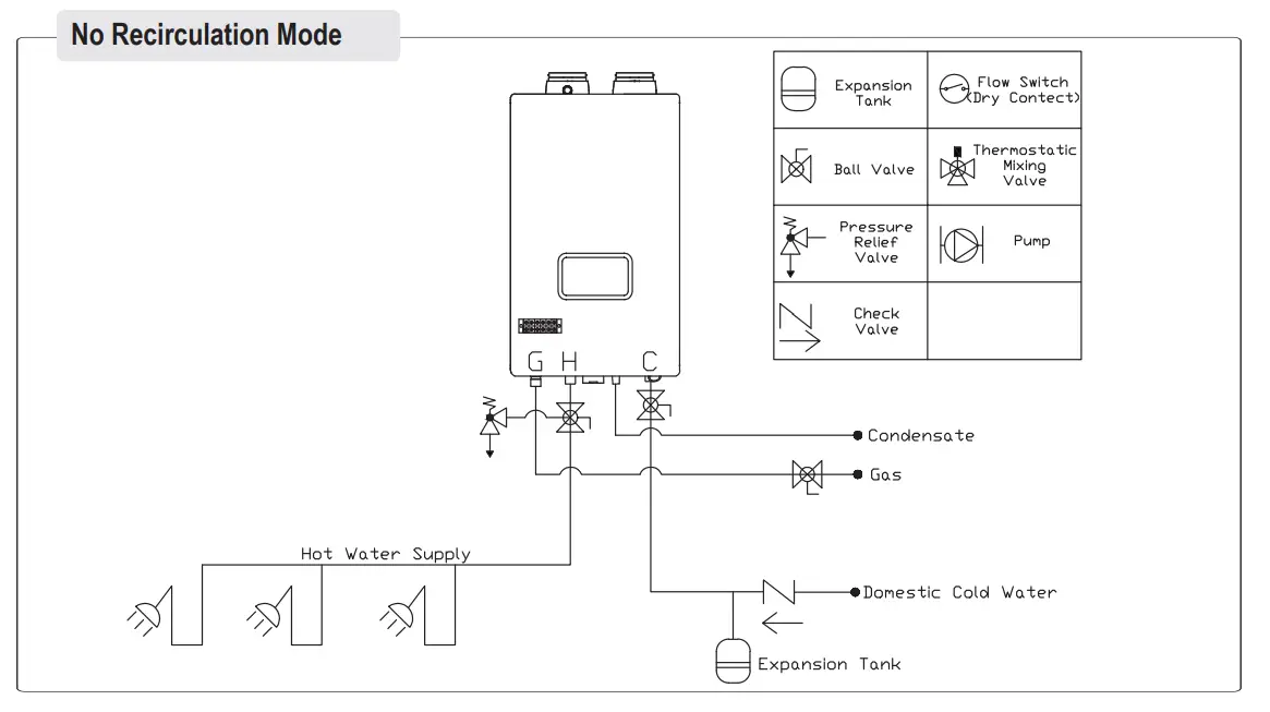 Pulse Mode
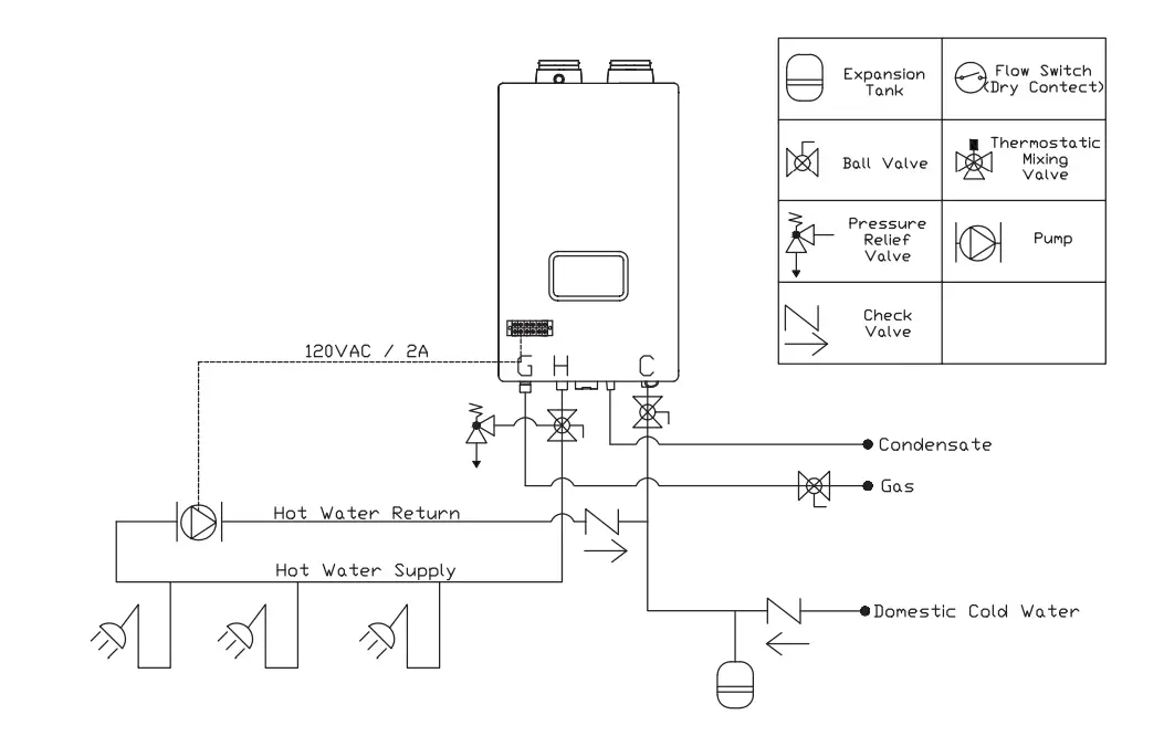
| Mode | Description | Setting | Requirements | Performance | |
| 12:Ah | Dedicated Return Line | Accessory | Energy Savings | ||
| Standard Air Handler | Pairs with Air handler for space heat. | Std | Yes | Thermostatic Mixing valve | Good |
| Eco Air Handler | Incorporates DHW priority switch and anti-legionella function | ECO | Yes | Thermostatic mixing valve, DHW priority switch | Better |
Air Handler Standard Mode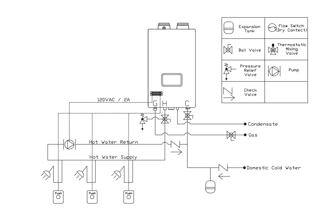
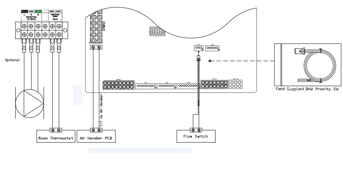
- Water heater receives signal from the Room Thermostat and it will control the Air Handler as per flow switch condition
- It prevents simultaneous operation of DHW and heating to eliminate cold wind during heating or lower water temperature during shower
- No usage during Anti oFF setting time, it can operate arbitrarily during the Anti on time for preventing bacteria in the heating pipe.
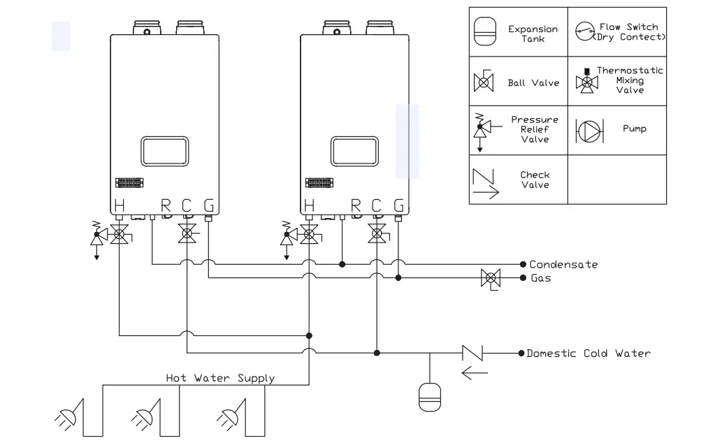
Multi-Unit Applications
Water Heater Mode (RTGR199N1, RTGR199X1)
|
Mode |
Description | Setting | Requirement | Performance | |||
| 11:RC | Dedicated Return Line | Accessory | Wait Time Water Savings | Energy Savings | Hot Water Temperature | ||
| No Recirculation | Same as regular tankless water heaters. | OFF | No | – | – | – | – |
| Internal | Hot water without dedicated return line. | Itnl | No | – | Better | Better | Better |
| External | Quick hot water with dedicated return line. | Etnl | Yes | – | Best | Better | Best |
| Crossover | Quick warm water without dedicated return line. | CrOS | No | O | Best | Good | Warm |
* Recirculation is activated byTimer [Auto / Manual]
|
Mode |
Description | Setting | Requirement | Performance | |||
| 13:Cn | Dedicated Return Line | Accessory | Wait Time Water Savings | Energy Savings | Hot Water Temperature | ||
| Cascaded | Multiple heaters used for increased heat capacity | 01:Leader 02:Follower 1 03:Follower 2 | No | Cascade Cable | – | – | – |
No Recirculation Mode, Internal Recirculation Mode
- Only POTABLE water may be plumbed through the water heater.
- The water heater cannot be used for space heating application
- Expansion tank is required if a backflow preventer is installed

Recirculation Mode [ External Mode]
- Provides most comfortable option. Maintains consistent hot water availability during specified times
- Timer can be manually customized or programmed to automatically learn daily usage patterns.
- Ability to optimize by using Installer Mode function 3: RT to adjust loop temperature for maximum comfort and safety.

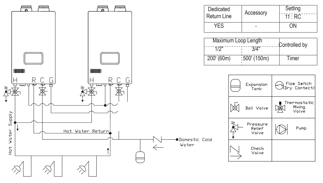
The recirculation return pipe must be installed in the field in order to apply the ‘External Mode’.
This mode allows the hot water pipes to be warmed up and also serves as the freeze protection function.
Recirculation Mode
Crossover(CrOS) Mode
- Provides recirculation option for homes without a dedicated return line by utilizing the cold water line as a return line.
- Timer can be manually customized or programmed to automatically learn daily usage patterns.
- In order to prevent hot water from being supplied into the cold water line, the thermal element in the crossover valve will close at about 95°F. As a result, hot water may not be available at all times (only warm water).

Water Heater Mode (RTGS199N1, RTGS199X1)
| Mode | Description | Setting | Requirement | Performance | |||
| 11:RC | Dedicated Return Line | Accessory | Wait Time Water Savings | Energy Savings | Hot Water Temperature | ||
| No Recirculation | Heat water as draws occur, no recirculation occurs | OFF | No | – | – | – | – |
| Pulse* | Unit controls an External pump with a dedicated return | PuLS | No | – | Best | Better | Best |
*Models not equipt with a built-in pump will require a field supplied circulator to be installed for use with recirculation modes, See section 3.6 Water Heater Sizing for pressure curves for circulator sizing.
No Recirculation Mode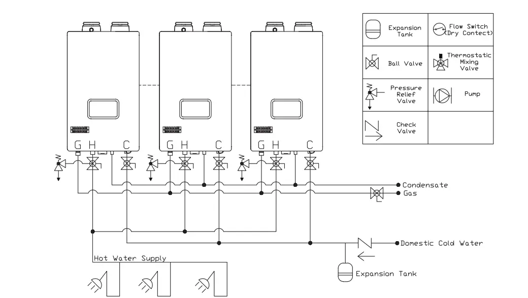 Pulse Mode
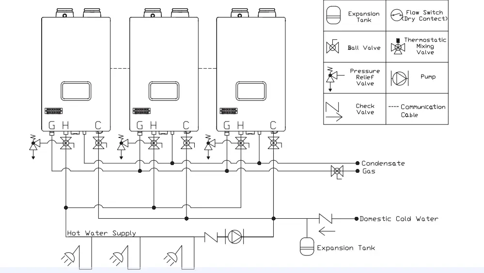
United States
SALE 800-523-2931
Technical Support:800-334-3393
Email [email protected]
WarrantY:[email protected]
[email protected]
[email protected]
[email protected] For U.S. and Canada field service, contact your professional installer or local Bradford White sales representative. International
General Contact [email protected]
©2022, Bradford White Corporation, USA. All rights reserved. www.bradfordwhite.com


