innon Core IO CR-IO-8DI 8 Point Modbus Input or Output Module User Manual
INTRODUCTION
Overview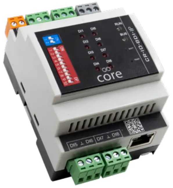
In many installations, having cost effective, robust, and simple hardware becomes a key factor in winning a project. The Core line up provides the perfect solution to meet these criteria. Innon have partnered with Atimus, a company with a wealth of experience in the field, and are proud to present Core IO!
The 8DI provides 8 digital inputs. As well as monitoring volt free contacts, the device also allows the use of pulse counters.
BEMS communication is based on the robust and well proven Modbus RTU over RS485 or Modbus TCP (IP model only).
The configuration of the device can be achieved through the network using either the web interface (IP version only) or Modbus configuration registers, or by using an Android device and connecting over Bluetooth using the dedicated app.
This Core IO model
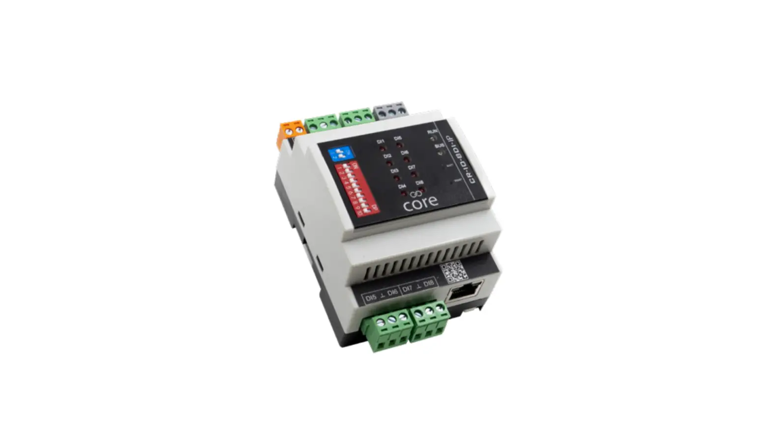
Both the CR-IO-8DI-RS and the CR-IO-8DI-IP modules come with 8 digital inputs.
The CR-IO-8DI-RS only comes with the RS485 port, while the CR-IO-8DI-IP comes with both RS485 and IP ports.
Both models also come with Bluetooth on-board, so configuration can be achieved using an Android device and the dedicated app.
The IP CR-IO-8DI-IP model also integrates a web server configuration interface, accessible via a PC web browser.
HARDWARE
Overview 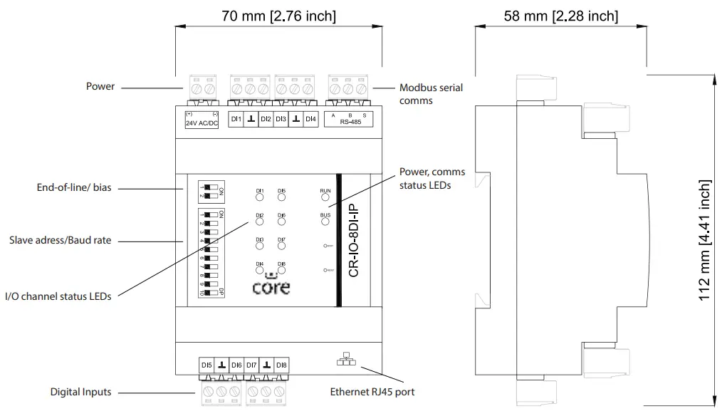
Wiring Power Supply 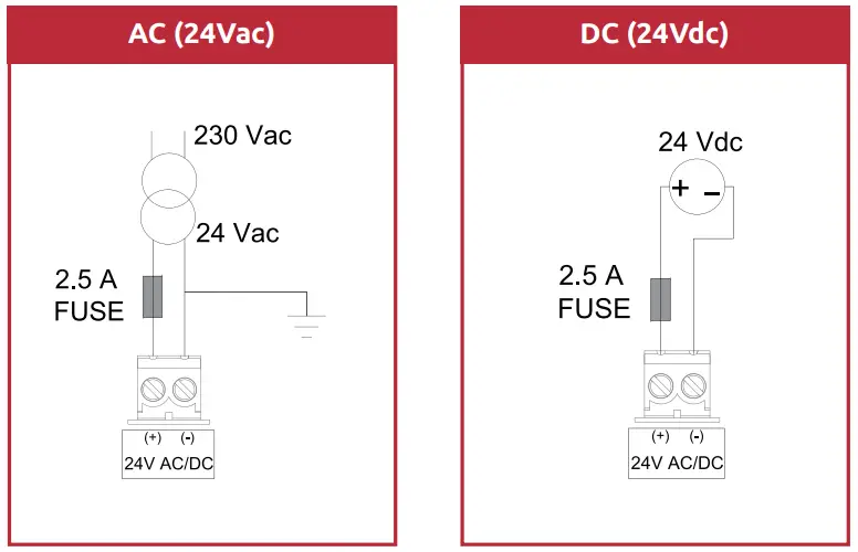
Wiring Digital Inputs (DI) 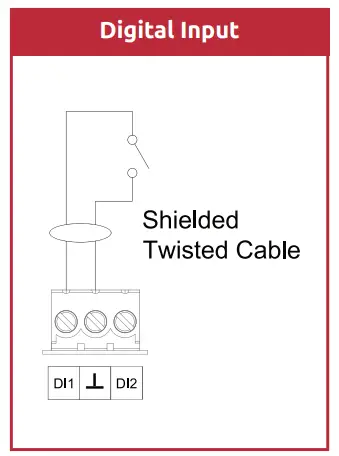
Wiring the RS485 network
Some useful links to our knowledge base website:
How to wire an RS485 network
https://know.innon.com/howtowire-non-optoisolated
How to terminate and bias an RS485 network
https://know.innon.com/bias-termination-rs485-network
Please note – both IP and RS versions can use the RS485 port to respond to serial Modbus master comms from the BEMS, but neither version can use the RS485 port to act as a Modbus master or gateway.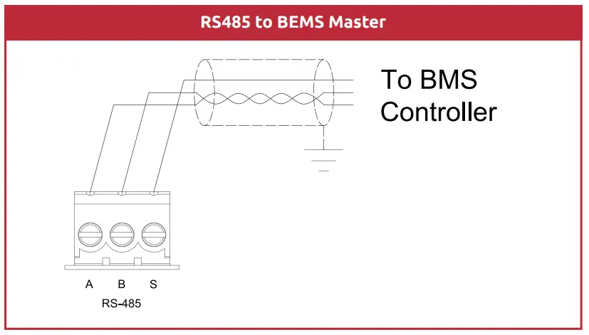
Front LED Panel
The LEDs in the front panel can be used to get direct feedback on the status of the I/Os of Core IO and more general information.
Below are some tables that will help decode each LED behaviour –
DI 1 to 8
| Digital Input Mode | Conditions | LED Status |
| Direct | Open Circuit Short circuit | LED OFF LED OFF |
| Revers | Open Circuit Short circuit | LED OFF LED OFF |
| Pulse input | Receiving a pulse | LED Blinks ON for every pulse |
BUS and RUN
| LED | Conditions | LED Status |
| RUN | Core IO not powered Core IO correctly powered | LED OFF LED ON |
| BUS | Data being received Data being transmitted Bus polarity problem | LED blinks Red LED blinks Blue LED ON Red |
CONFIGURE I/O
Digital Inputs
Digital Inputs can have a clean/volt free contact connected to Core IO to read its open/closed status.
Each digital input can be configured to be either:
- Digital Input direct
- Digital Input reverse
- Pulse input
While the “direct” and “reverse” mode would basically return status “False (0)” or “True (1)” when the contact is either open or closed, the third mode “pulse input” is used to return a counter value increasing by 1 unit every time the digital input closes; please read section below for more details regarding pulse counting.
Pulse Counting
Digital Inputs and Universal Outputs can be configured specifically to work as pulse counting inputs.
The counting maximum readable frequency is 100Hz, with a duty cycle of 50% and the maximum “contact closed” readable resistance is 50ohm.
When an input is configured to count pulses, a number of Modbus Registers are available with information and commands specifically for the pulse counting function.
The pulse input will, in fact count 2 totalizers as follows –
- The first one is continuous; it will increase by one unit for every pulse received and will keep counting until a reset command is sent over Modbus
- The other totalizer is timed. Basically, it will also increase by one unit for every pulse received but will count only for a specified (adjustable) time (in minutes). When the time expires, this second counter will start counting again from “0” immediately, repeating the cycle, but will hold the last resulting value for a minute in the register (counting the next cycle in the background)
Each pulse counting input has the following Modbus registers associated with it –
- counter (totalizer): this is the main totalizer. It will go back to “0” only if a reset command is sent, or if Core IO is power cycled – you can also write to this value to restore a previous count if replacing a module or to reset to 0
- counter (timer): this is the second totalizer, the timed one. It will go back to “0” every time the timer reaches the maximum set value (with delay of 1 minute), or if Core IO is power cycled. If the counter reset is activated, the counts within the timed cycle will be ignored and the counter timer reset to 0. The reset will not reset this count to 0 after it has finished a timed cycle and is displaying the result for 1 minute
- counter timer: this data point returns the current time of the counter, in minutes. It will of course go back to “0” when it reaches the maximum set value
- counter timer set: using this data point you can configure the duration of the timer for the second totalizer (max set value), in minutes. This value is stored within the Core IO memory
- counter reset: using this data point you can reset totaliser counter to value “0” and the timed counter will discard counts up to that point in the timed cycle and reset its timer to 0. Core IO will self-reset this data point to value “0” once the command has been executed.
CONFIGURING THE DEVICE
FIXED SETTINGS
The RS485 Modbus Slave communication have some settings that are fixed as follows –
- 8-bit data length
- 1 stop bit
- Parity NONE
DIP SWITCH SETTING
The DIP switches are used to configure the other RS485 settings and the Modbus slave address thus –
- RS485 End-Of-Line (EOL) resistor
- RS485 Bias resistors
- Modbus Slave Address
- RS485 Baud-Rate
The bank of two EOL (End-Of-Line) blue DIP switches are configured as follows –
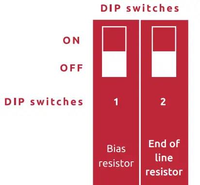 | ||
| No bias, no termination | OFF | OFF |
| Bias active, no termination | ON | OFF |
| No bias, termination active | OFF | ON |
| Bias active, termination active | ON | ON |
Please check our dedicated knowledge base article available at the website http://know.innon.com where we explain in detail the use of the termination and bias resistors on RS485 networks.
The Modbus ID and baud rate DIP switches are configured as follows –
 | ||||||||||
| Slave address | Baud rate | |||||||||
| 1 | ON | OFF | OFF | OFF | OFF | OFF | OFF | OFF | OFF | 4800 Kbps |
| 2 | OFF | ON | OFF | OFF | OFF | OFF | ON | OFF | OFF | 9600 Kbps |
| 3 | ON | ON | OFF | OFF | OFF | OFF | OFF | ON | OFF | 19200 Kbps |
| 4 | OFF | OFF | ON | OFF | OFF | OFF | ON | ON | OFF | 38400 Kbps |
| 5 | ON | OFF | ON | OFF | OFF | OFF | OFF | OFF | ON | 57600 Kbps |
| 6 | OFF | ON | ON | OFF | OFF | OFF | ON | OFF | ON | 76800 Kbps |
| 7 | ON | ON | ON | OFF | OFF | OFF | OFF | ON | ON | 115200 Kbps |
| 8 | OFF | OFF | OFF | ON | OFF | OFF | ON | ON | ON | 230400 Kbps |
| 9 | ON | OFF | OFF | ON | OFF | OFF | ||||
| 10 | OFF | ON | OFF | ON | OFF | OFF | ||||
| 11 | ON | ON | OFF | ON | OFF | OFF | ||||
| 12 | OFF | OFF | ON | ON | OFF | OFF | ||||
| 13 | ON | OFF | ON | ON | OFF | OFF | ||||
| 14 | OFF | ON | ON | ON | OFF | OFF | ||||
| 15 | ON | ON | ON | ON | OFF | OFF | ||||
| 16 | OFF | OFF | OFF | OFF | ON | OFF | ||||
| 17 | ON | OFF | OFF | OFF | ON | OFF | ||||
| 18 | OFF | ON | OFF | OFF | ON | OFF | ||||
| 19 | ON | ON | OFF | OFF | ON | OFF | ||||
| 20 | OFF | OFF | ON | OFF | ON | OFF | ||||
| 21 | ON | OFF | ON | OFF | ON | OFF | ||||
| 22 | OFF | ON | ON | OFF | ON | OFF | ||||
| 23 | ON | ON | ON | OFF | ON | OFF | ||||
| 24 | OFF | OFF | OFF | ON | ON | OFF | ||||
| 25 | ON | OFF | OFF | ON | ON | OFF | ||||
| 26 | OFF | ON | OFF | ON | ON | OFF | ||||
| 27 | ON | ON | OFF | ON | ON | OFF | ||||
| 28 | OFF | OFF | ON | ON | ON | OFF | ||||
Slave address DIP switch settings, continued.
 | ||||||
| Slave address | ||||||
| 29 | ON | OFF | ON | ON | ON | OFF |
| 30 | OFF | ON | ON | ON | ON | OFF |
| 31 | ON | ON | ON | ON | ON | OFF |
| 32 | OFF | OFF | OFF | OFF | OFF | ON |
| 33 | ON | OFF | OFF | OFF | OFF | ON |
| 34 | OFF | ON | OFF | OFF | OFF | ON |
| 35 | ON | ON | OFF | OFF | OFF | ON |
| 36 | OFF | OFF | ON | OFF | OFF | ON |
| 37 | ON | OFF | ON | OFF | OFF | ON |
| 38 | OFF | ON | ON | OFF | OFF | ON |
| 39 | ON | ON | ON | OFF | OFF | ON |
| 40 | OFF | OFF | OFF | ON | OFF | ON |
| 41 | ON | OFF | OFF | ON | OFF | ON |
| 42 | OFF | ON | OFF | ON | OFF | ON |
| 43 | ON | ON | OFF | ON | OFF | ON |
| 44 | OFF | OFF | ON | ON | OFF | ON |
| 45 | ON | OFF | ON | ON | OFF | ON |
| 46 | OFF | ON | ON | ON | OFF | ON |
| 47 | ON | ON | ON | ON | OFF | ON |
| 48 | OFF | OFF | OFF | OFF | ON | ON |
| 49 | ON | OFF | OFF | OFF | ON | ON |
| 50 | OFF | ON | OFF | OFF | ON | ON |
| 51 | ON | ON | OFF | OFF | ON | ON |
| 52 | OFF | OFF | ON | OFF | ON | ON |
| 53 | ON | OFF | ON | OFF | ON | ON |
| 54 | OFF | ON | ON | OFF | ON | ON |
| 55 | ON | ON | ON | OFF | ON | ON |
| 56 | OFF | OFF | OFF | ON | ON | ON |
| 57 | ON | OFF | OFF | ON | ON | ON |
| 58 | OFF | ON | OFF | ON | ON | ON |
| 59 | ON | ON | OFF | ON | ON | ON |
| 60 | OFF | OFF | OFF | ON | ON | ON |
| 61 | ON | OFF | ON | ON | ON | ON |
| 62 | OFF | ON | ON | ON | ON | ON |
| 63 | ON | ON | ON | ON | ON | ON |
Bluetooth and Android App
Core IO has built-in Bluetooth which allows the Core Settings app running on an Android device to configure the IP settings and I/O.
Please download the app from Google Play – search for “core settings”
Download and install the app, then check/make the following settings changes –
- Open your phone settings (drag down from top, press “cog” icon)
- Click on “Apps”
- Select “Core Settings” app
- Press “Permissions”
- Press “Camera” – set to “Allow only while using the app”
- Go back then press “Nearby devices” – set to “Allow”
When you run the app, the camera will switch on, and you will need to use it to read the QR code on the module you wish to set up, i.e. –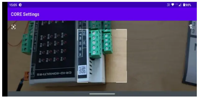
The Android device will ask you to allow the Bluetooth devices to pair on the first connection, watch out for the notifications on your device and accept them.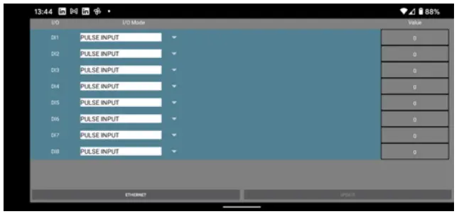
Once connected, you will land on the I/O setup screen, where you can set up the I/O and read input and output current values –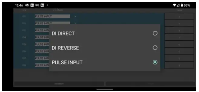
Use the drop-down arrows in the “I/O Mode” column to select the type of input type by clicking in the respective radio button –
Once you make a change or number of changes, the “UPDATE” button on the bottom right will go from greyed-out to white; press this to commit your changes.
Click on the “ETHERNET” button (bottom left) to set-up the required IP settings. Set and commit data as per the I/O method above.
Click on “MODE” button (bottom left) to get back to the I/O settings.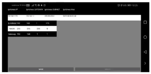
Ethernet Port and Web Server Configuration (IP version only)
For the IP models of Core IO, a standard RJ45 socket is available to be used for:
- Modbus TCP (slave) communication
- Web server access to configure the device
The IP models still provide access on the RS485 port for Modbus RTU (slave) communication on these models, so the user can decide which one to use to connect the BEMS to Core IO.
The default settings of the IP port are:
IP address: 192.168.1.175
Subnet: 255.255.255.0
Gateway address: 192.168.1.1
Modbus TCP port: 502 (fixed)
Http port (web server): 80 (fixed)
Web server user: atimus (fixed)
Web server password: HD1881 (fixed)
IP address, subnet and gateway address can be changed from the Bluetooth Android app or from the web server interface.
The web server interface looks and works in much the same way as the Core Settings app described in the previous section.
BEMS POINT LISTS
Modbus Register Types
Unless otherwise stated in the tables, all I/O point values/statuses and settings are held as Holding Register Modbus data type and use a single register (16 bit) to represent an Integer (Int, range 0 – 65535) type of data.
Pulse count registers are 32-bit long, unsigned registers, i.e. two consecutive 16 bit registers combined, and their byte order is sent in little endian, i.e. –
- Niagara/Sedona Modbus driver – 1032
- Teltonika RTU xxx – 3412 – also use 2 x “Register count/values” to obtain all 32 bits
For some Modbus master devices, the decimal and hex register addresses in the table will need to be incremented by 1 to read the correct register (e.g. Teltonika RTU xxx)
Bit-field data type uses individual bits from the 16 bits available on the Modbus register to provide multiple Boolean information by reading or writing a single register.
Modbus Register Tables
General Points
| Decimal | Hex | Name | Details | Stored | Type | Range |
| 3002 | BBA | Firmware version – units | Most significant number for firmware version e.g. 2.xx | YES | R | 0-9 |
| 3003 | BBB | Firmware version – tenths | 2nd Most significant number for firmware version e.g. x.0x | YES | R | 0-9 |
| 3004 | BBC | Firmware version – hundredths | 3rd Most significant number for firmware version e.g. x.x4 | YES | R | 0-9 |
Digital Input Points
| Decimal | Hex | Name | Details | Stored | Type | Range | |
| 99 | 28 | DI 1 mode | Digital Input mode select: 0 = Digital Intput direct 1 = Digital Intput reverse 2 = Pulse input | YES | R/W | 0…2 | |
| 100 | 29 | DI 2 mode | |||||
| 101 | 2A | DI 3 mode | |||||
| 102 | 2B | DI 4 mode | |||||
| 103 | 2C | DI 5 mode | |||||
| 104 | 2D | DI 6 mode | |||||
| 105 | 2E | DI 7 mode | |||||
| 106 | 2F | DI 8 mode | |||||
| 0 | 0 | DI 1 | Read Digital Input status (digital input mode): 0 = inactive 1 = active | YES | R | 0…1 | |
| 1 | 1 | DI 2 | |||||
| 2 | 2 | DI 3 | |||||
| 3 | 3 | DI 4 | |||||
| 4 | 4 | DI 5 | |||||
| 5 | 5 | DI 6 | |||||
| 6 | 6 | DI 7 | |||||
| 7 | 7 | DI 8 | |||||
| 1111 | 457 | DI 1-8 | Read digital input status by bit (only digital input mode, bit 0 = DI 1) | NO | R | 0…1 | |
| 9 | 9 | DI 1 counter (totalizer) | Read digital input status by bit (only digital input mode, bit 0 = DI 1) | NO | R/W | 0…4294967295 | |
| 11 | B | DI 1 counter (timer) | 32 bit long, counter value for the running timer (pulse input mode) | NO | R | 0…4294967295 | |
| 13 | D | DI 1 counter timer | Running timer in minutes. Will reset once “counter timer set” reached and start again | NO | R | 0…14400 | |
| 14 | E | DI 1 counter timer set | Timer duration configuration in minutes | YES | R/W | 0…14400 | |
| 15 | F | DI 1 counter reset | Reset command to all counted values (goes back to “0” automatically) | NO | R/W | 0…1 | |
| 16 | 10 | DI 2 counter (totalizer) | 32 bit long, total counter value (totalizer) (pulse input mode) | NO | R/W | 0…4294967295 | |
| 18 | 12 | DI 2 counter (timer) | 32 bit long, counter value for the running timer (pulse input mode) | NO | R | 0…4294967295 | |
| 20 | 14 | DI 2 counter timer | Running timer in minutes. Will reset once “counter timer set” reached and start again | NO | R | 0…14400 | |
| 21 | 15 | DI 2 counter timer set | Timer duration configuration in minutes | YES | R/W | 0…14400 | |
| 22 | 16 | DI 2 counter reset | Reset command to all counted values (goes back to “0” automatically) | NO | R/W | 0…1 | |
| 23 | 17 | DI 3 counter (totalizer) | 32 bit long, total counter value (totalizer) (pulse input mode) | NO | R/W | 0…4294967295 | |
| 25 | 19 | DI 3 counter (timer) | 32 bit long, counter value for the running timer (pulse input mode) | NO | R | 0…4294967295 | |
| 27 | 1B | DI 3 counter timer | Running timer in minutes. Will reset once “counter timer set” reached and start again | NO | R | 0…14400 | |
| 28 | 1C | DI 3 counter timer set | Timer duration configuration in minutes | YES | R/W | 0…14400 | |
| 29 | 1D | DI 3 counter reset | Reset command to all counted values (goes back to “0” automatically) | NO | R/W | 0…1 | |
| 30 | 1E | DI 4 counter (totalizer) | 32 bit long, total counter value (totalizer) (pulse input mode) | NO | R/W | 0…4294967295 | |
| 32 | 20 | DI 4 counter (timer) | 32 bit long, counter value for the running timer (pulse input mode) | NO | R | 0…4294967295 | |
| 34 | 22 | DI 4 counter timer | Running timer in minutes. Will reset once “counter timer set” reached and start again | NO | R | 0…14400 | |
| 35 | 23 | DI 4 counter timer set | Timer duration configuration in minutes | YES | R/W | 0…14400 | |
| 36 | 24 | DI 4 counter reset | Reset command to all counted values (goes back to “0” automatically) | NO | R/W | 0…1 | |
| 37 | 25 | DI 5 counter (totalizer) | 32 bit long, total counter value (totalizer) (pulse input mode) | NO | R/W | 0…4294967295 | |
| 39 | 27 | DI 5 counter (timer) | 32 bit long, counter value for the running timer (pulse input mode) | NO | R | 0…4294967295 | |
| 41 | 29 | DI 5 counter timer | Running timer in minutes. Will reset once “counter timer set” reached and start again | NO | R | 0…14400 | |
| 42 | 2A | DI 5 counter timer set | Timer duration configuration in minutes | YES | R/W | 0…14400 | |
| 43 | 2B | DI 5 counter reset | Reset command to all counted values (goes back to “0” automatically) | NO | R/W | 0…1 | |
| 44 | 2C | DI 6 counter (totalizer) | 32 bit long, total counter value (totalizer) (pulse input mode) | NO | R/W | 0…4294967295 | |
| 46 | 2E | DI 6 counter (timer) | 32 bit long, counter value for the running timer (pulse input mode) | NO | R | 0…4294967295 | |
| 48 | 30 | DI 6 counter timer | Running timer in minutes. Will reset once “counter timer set” reached and start again | NO | R | 0…14400 | |
| 49 | 31 | DI 6 counter timer set | Timer duration configuration in minutes | YES | R/W | 0…14400 | |
| 50 | 32 | DI 6 counter reset | Reset command to all counted values (goes back to “0” automatically) | NO | R/W | 0…1 | |
| 51 | 33 | DI 7 counter (totalizer) | 32 bit long, total counter value (totalizer) (pulse input mode) | NO | R/W | 0…4294967295 | |
| 53 | 35 | DI 7 counter (timer) | 32 bit long, counter value for the running timer (pulse input mode) | NO | R | 0…4294967295 | |
| 55 | 37 | DI 7 counter timer | Running timer in minutes. Will reset once “counter timer set” reached and start again | NO | R | 0…14400 | |
| 56 | 38 | DI 7 counter timer set | Timer duration configuration in minutes | YES | R/W | 0…14400 | |
| 57 | 39 | DI 7 counter reset | Reset command to all counted values (goes back to “0” automatically) | NO | R/W | 0…1 | |
| 58 | 3A | DI 8 counter (totalizer) | 32 bit long, total counter value (totalizer) (pulse input mode) | NO | R/W | 0…4294967295 | |
| 60 | 3C | DI 8 counter (timer) | 32 bit long, counter value for the running timer (pulse input mode) | NO | R | 0…4294967295 | |
| 62 | 3E | DI 8 counter timer | Running timer in minutes. Will reset once “counter timer set” reached and start again | NO | R | 0…14400 | |
| 64 | 40 | DI 8 counter timer set | Timer duration configuration in minutes | YES | R/W | 0…14400 | |
| 65 | 41 | DI 8 counter reset | Reset command to all counted values (goes back to “0” automatically) | NO | R/W | 0…1 | |
TECHNICAL DATA
Drawings
Part number: CR-IO-8DI-RS
Part number: CR-IO-8DI-IP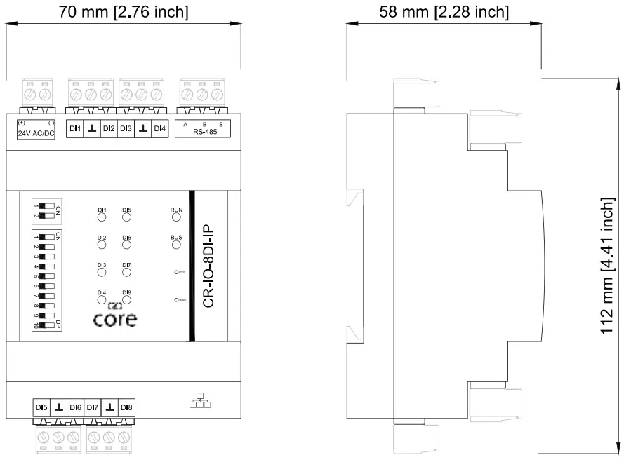
Specifications
| Power supply | 24 Vac +10%/-15% 50 Hz, 24 Vdc +10%/-15% |
| Current draw – 70mA min, 80mA max | |
| Digital Inputs | 8 x Digital Inputs (volt free) |
| DI direct, DI reverse, PULSE (up to 100 Hz, 50% duty cycle, max 50 ohm contact) | |
| Interface to BEMS | RS485, opto-isolated, max 63 devices supported on the network |
| Ethernet/IP (IP version) | |
| Protocol to BEMS | Modbus RTU, baud rate 9600 – 230400, 8 bit, no parity, 1 stop bit |
| Modbus TCP (IP version) | |
| Ingress Protection R ating | IP20, EN 61326-1 |
| Temperature and humidity | Operating: 0°C to +50°C (32°F to 122°F), max 95% RH (without condensation) |
| Storage: -25°C to +75°C (-13°F to 167°F), max 95% RH (without condensation) | |
| C onnect ors | Plug-in Terminals 1 x 2.5 mm2 |
| Mounting | Panel mounted (2x on-board sliding screw holders on the back) / DIN rail mounting |
Guidelines for Disposal
- The appliance (or the product) must be disposed of separately in accordance with the local waste disposal legislation in force.
- Do not dispose of the product as municipal waste; it must be disposed of through specialist waste disposal centres.
- Improper use or incorrect disposal of the product may negatively affect human health and the environment.
- In the event of illegal electrical and electronic waste disposal, the penalties are specified by local waste disposal legislation.
1.0 4/10/2021
Get help at http://innon.com/support
Learn more at http://know.innon.com