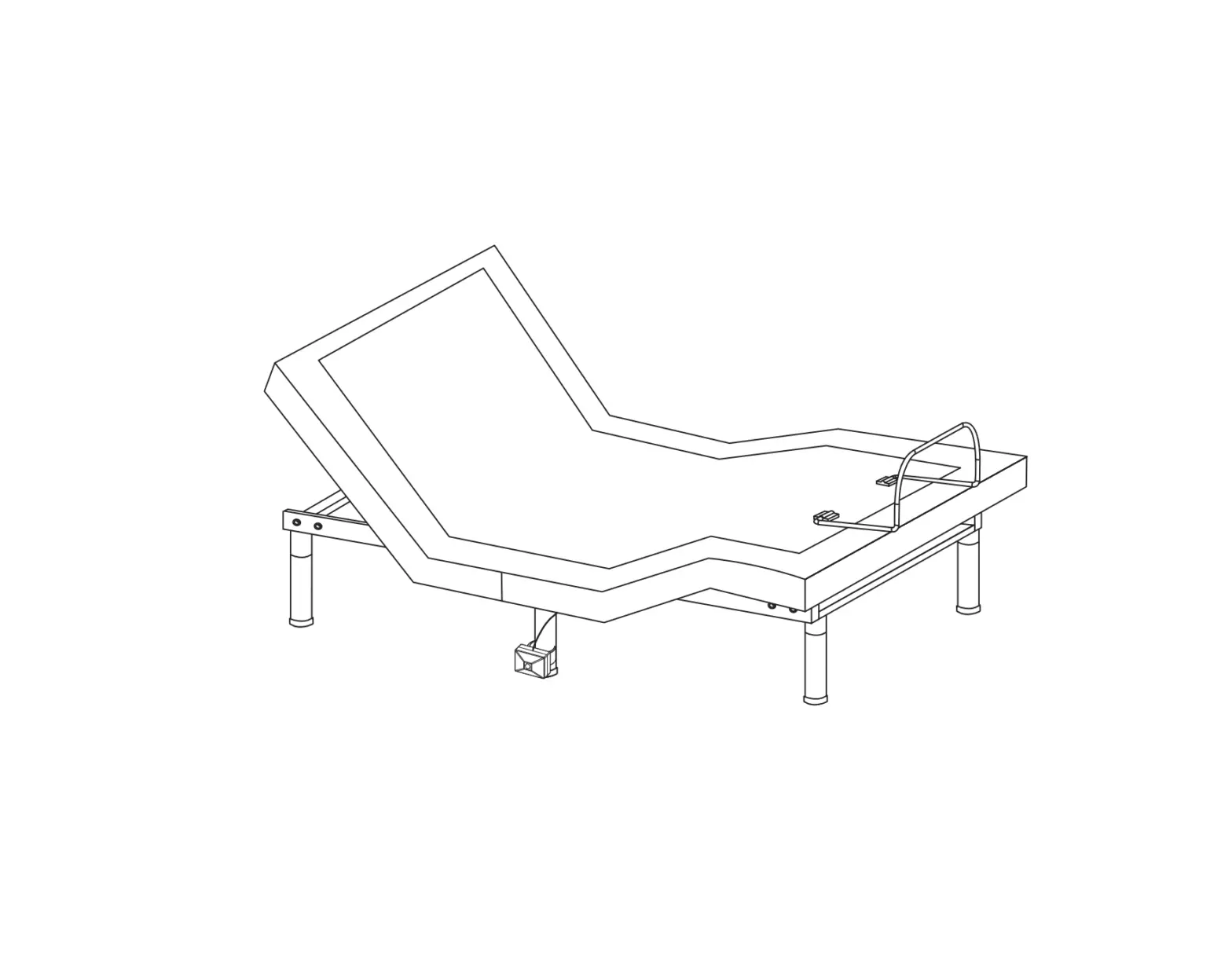
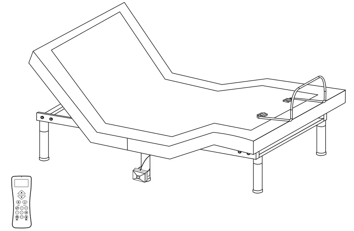
Moto Sleep SFAB350MSATXL Low Profile Bed With Motion Sensor And Audio System
Setup the power foundation without the bed frame
- Open the box lid.

- Take out all the accessories from the packaging and put them aside. All electronics and components that need to be installed are located in boxes under the foundation or attached to the frame. Before discarding the packing materials, ensure that all the parts are accounted for.


ACCESSORIES BOX
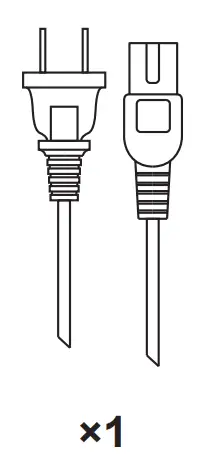
Adjustable Legs Remote Control Power Supply with Battery Backup Box AC Power Cord 


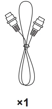
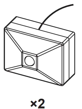
Sync Cord (TXL/T/CKS Only) AAA Batteries Mounting Bracket Motion Sensor 


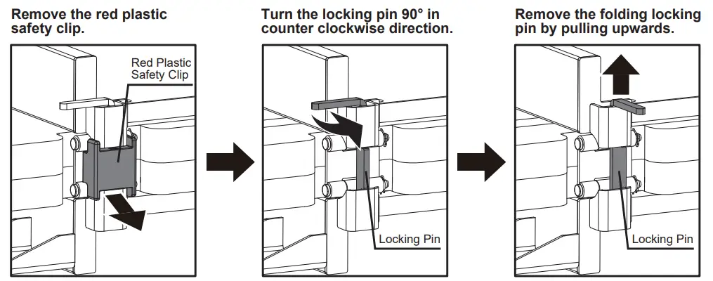
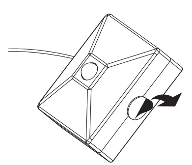
- Remove the red plastic safety lock before unfolding your power foundation.

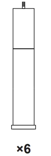
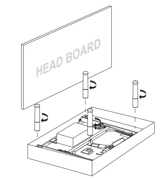
- Install 4 legs, make sure the legs are tight.

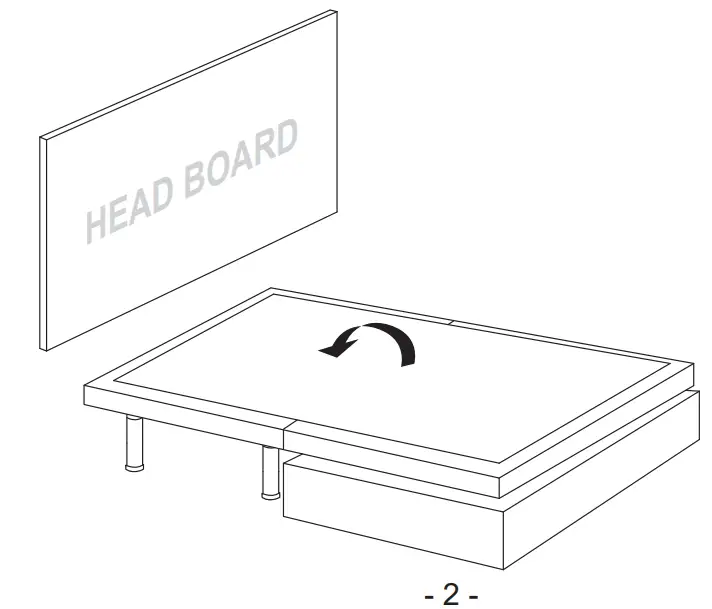
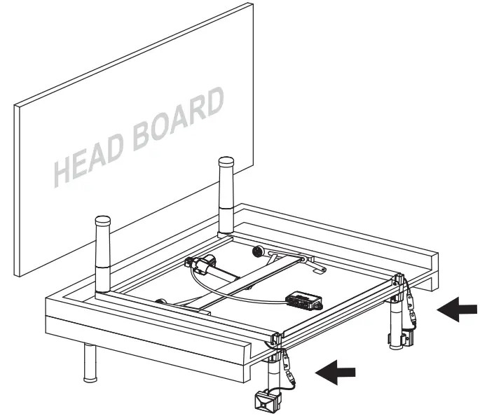
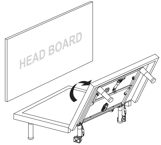
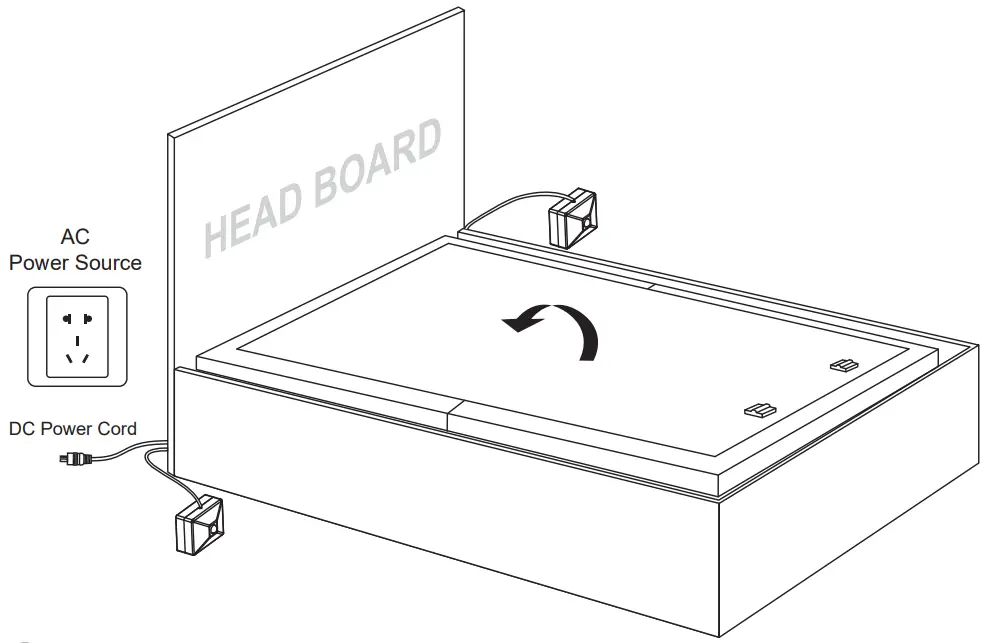
- Remove the bed from the box with a flipping motion, let the bed stand on the 4 legs.

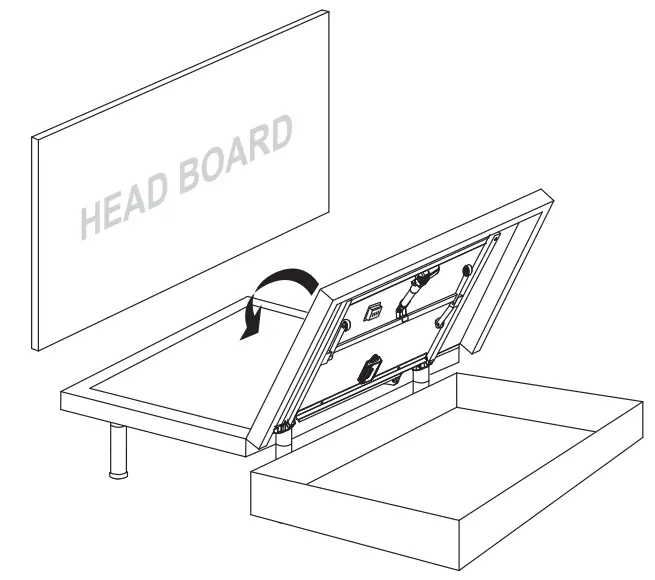
- Flip the foot end of the bed from the box and lay it on top of the end at the headboard.

- Install the remaining 2 legs on the foot end of the bed, make sure the legs are tight. Uncoil the DC power cord (connected to the control box) and put it to the side of the bed.

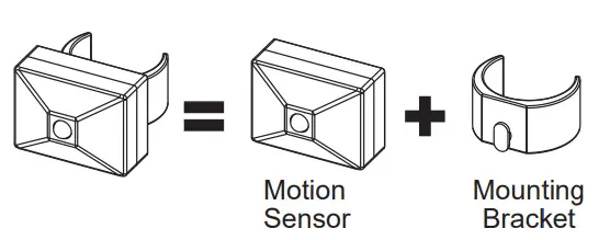
- Motion sensor installation.

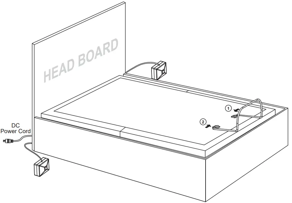
Prepare The Motion Sensor Hardware


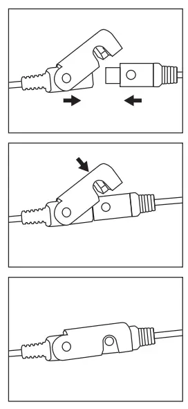
Connect The Motion Sensor Connectors
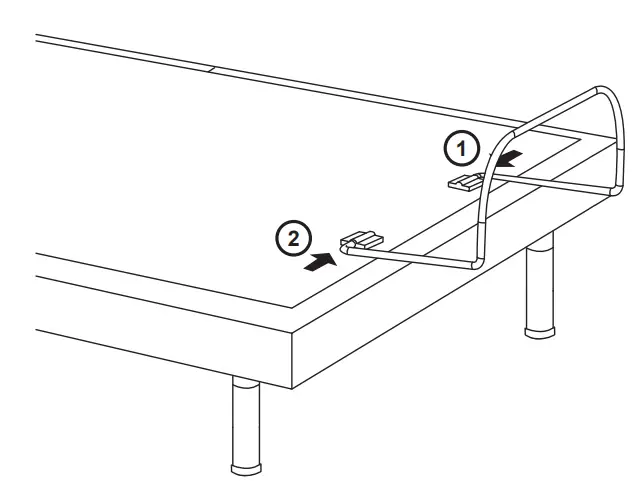
STEP 1: Clip the mounting bracket onto the center adjustable legs as illustrated.

STEP 2: Connect the motion sensor connectors as illustrated. Note there are two connectors, one on each side of the bed.
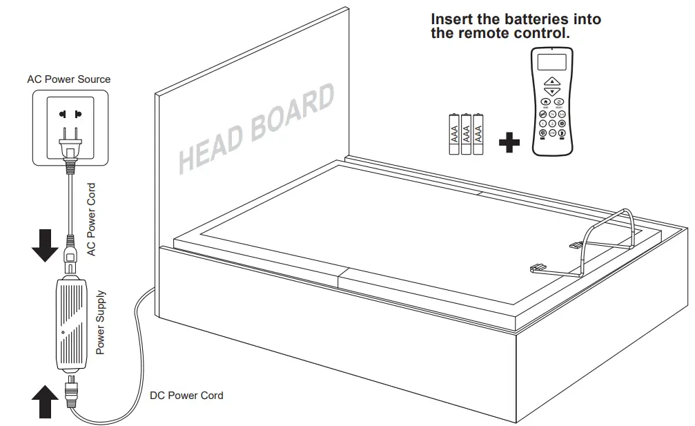
- Make the bed completely flat.

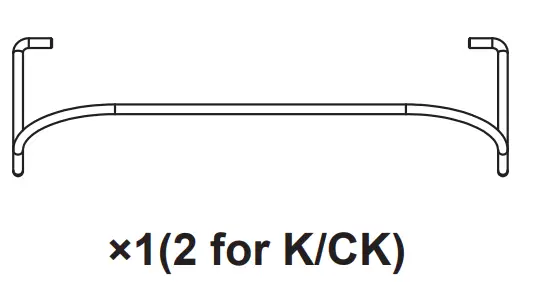
- Install the mattress retainer bar one side after another.

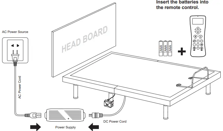
- Uncoil the AC power cord, connect the DC power cord to the power supply and then connect the power supply to the AC power source.


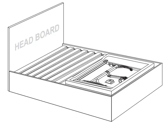
Setup the power foundation with the bed frame and slat base
- Take the bed out of the box, put it on the slat base, do not install any legs.

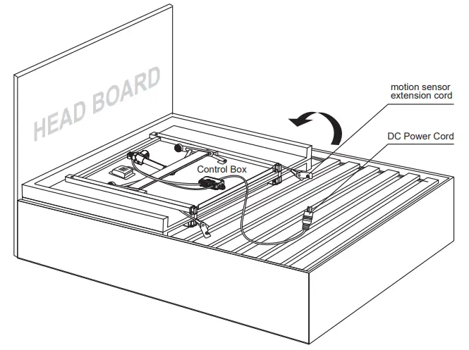
- Turn over the bed. Uncoil the DC power cord.

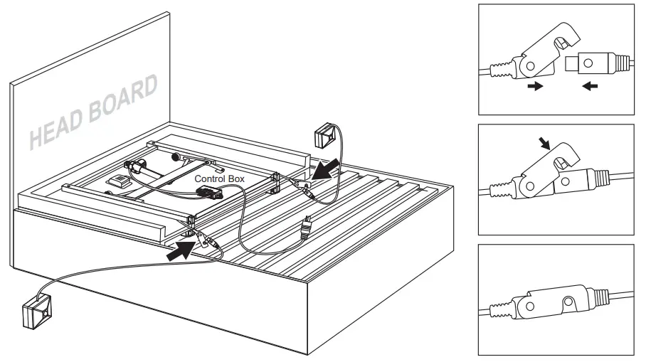
- Motion sensor installation
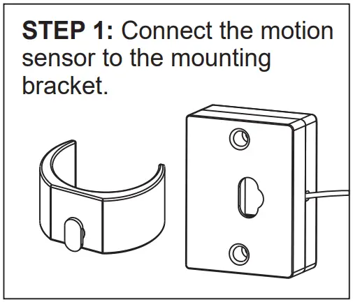
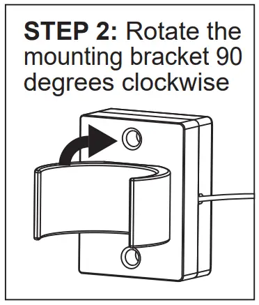
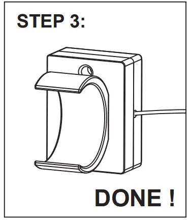
STEP 1: Connect the motion sensor connectors as illustrated.
STEP 2: Use the double sided tape to secure the motion sensor when necessary.
- Pull the DC power cord towards the direction of the AC power source through either the bottom or the side of the bed frame. Pull the two motion sensors to the two sides of the bed frame. Make the bed completely flat with a flipping motion.

- Install the mattress retainer bar one side after another.

- Uncoil the AC power cord, connect the DC power cord to the power supply and then connect the power supply to the AC power source.

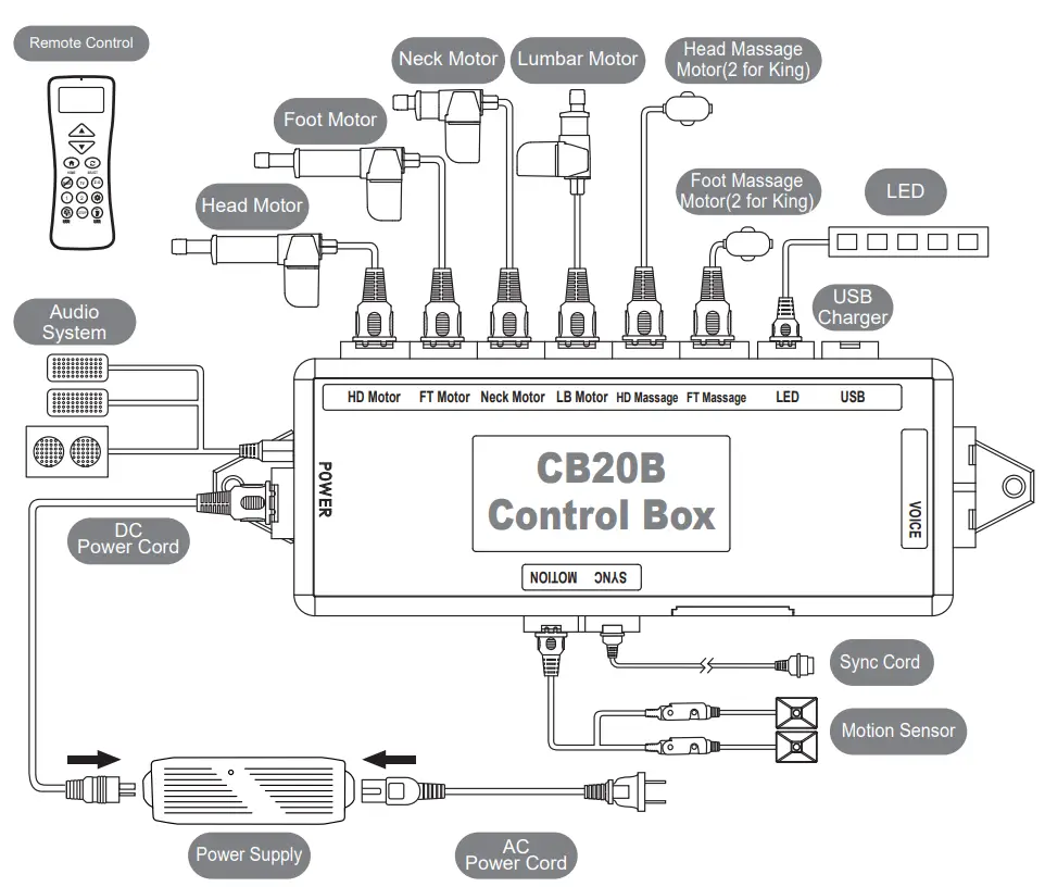
Electronics Quick Reference Guide
Synchronizing Two Foundations with Sync Cord
STEP 1:Unplug foundations from the power source.
STEP 2:Connect the male ends of the sync cord to the female sync plugs of the control boxes (Refer to below illustration).
STEP 3:Plug foundations back into the power source.
STEP 4:Check to ensure all cords are securely attached. Either remote will operate both foundations simultaneously.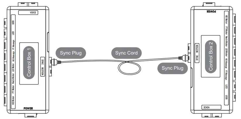
If simultaneous operation of two foundations is desired, please follow the steps listed below. Note the sync cord is needed to control two foundations with mobile APP, follow the “Synchronizing Two Foundations with Sync Cord” instruction to install the sync cord or follow the “Wireless Head Motor Syncing Instruction”.
Wireless Syncing Instruction
STEP 1:Make sure both remotes are individualy paired to the foundation. If the remote is not paired with the foundation, follow the pairing instructions.
STEP 2:Make sure both foundations are at home (flat position).
STEP 3:Press and hold ![]() and HOME
and HOME![]() on both remotes at the same time for 5 seconds until the LCD screen shows SYNC.
on both remotes at the same time for 5 seconds until the LCD screen shows SYNC.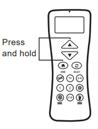
UN-SYNC Two Foundations
Press and hold![]() and
and ![]() on both remotes at the same time for 5 seconds, until the LCD screen flashes and shows UN-SYNC.
on both remotes at the same time for 5 seconds, until the LCD screen flashes and shows UN-SYNC.
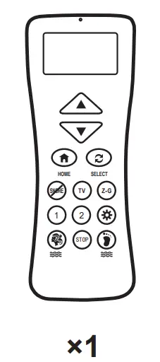
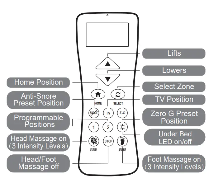
Remote Control Instructions
ADJUST
![]() This button lifts the Head/Foot/ Neck/Lumbar section of the foundation.
This button lifts the Head/Foot/ Neck/Lumbar section of the foundation.![]() This button lowers the Head/Foot/ Neck/Lumbar section of the foundation.
This button lowers the Head/Foot/ Neck/Lumbar section of the foundation.
SETTING PROGRAMMABLE POSITION
![]()
![]() One touch programmable positions.
One touch programmable positions.
MASSAGE FEATURES
![]() Turn on the head massage. Cycle through 3 massage intensities.
Turn on the head massage. Cycle through 3 massage intensities.![]() Turn on the foot massage. Cycle through 3 massage intensities.
Turn on the foot massage. Cycle through 3 massage intensities.![]() Turn off the head/foot massage.
Turn off the head/foot massage.
![]() One touch flat position.
One touch flat position.![]() One touch Select button. Select head or foot zone.
One touch Select button. Select head or foot zone.![]() One touch ANTI-SNORE preset position.
One touch ANTI-SNORE preset position.![]() One touch TV preset position.
One touch TV preset position.![]() One touch ZERO G preset position. ZERO G adjusts your legs to a higher level than your heart, helping to relieve pressure of the lower back and promote circulation.
One touch ZERO G preset position. ZERO G adjusts your legs to a higher level than your heart, helping to relieve pressure of the lower back and promote circulation.![]() One touch underneath LED lighting on/off.
One touch underneath LED lighting on/off.
Pairing Remote
The original remote that comes in the box is already paired to the foundation. No further action is required. In the event when the remote is not paired with the foundation, follow the pairing instructions below.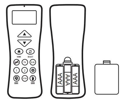
STEP 1:Make sure the batteries are good. Replace them when needed.
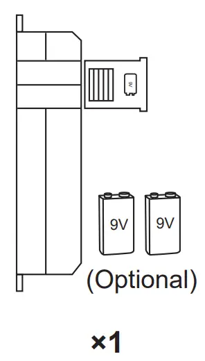
STEP 2: Unplug the power cord from the power source. If 9V backup batteries were installed in the power supply, remove them.
STEP 3: Press and hold Select button ![]() until the LCD screen of the remote control shows PAIR.
until the LCD screen of the remote control shows PAIR.
STEP 4: Plug the power cord back into the power source. You will hear an activation sound in 2 seconds, indicating the remote is paired to the power foundation.
Setting Programmable Position
STEP 1: Adjust the head, foot, neck and lumbar to your desired position.
STEP 2: Press and hold the program button ![]() for about 5 seconds until the LCD screen shows SAVE, and press picture programmable buttons
for about 5 seconds until the LCD screen shows SAVE, and press picture programmable buttons ![]()
![]() until you hear 2 beep sounds.
until you hear 2 beep sounds.
STEP 3: To adjust a saved position, repeat step 1 and 2 and the new position will be saved.
Setting Remote Lock
LOCK
Press and hold the HOME ![]() and SELECT
and SELECT![]() buttons simultaneously for about5 seconds until the LCD screen shows
buttons simultaneously for about5 seconds until the LCD screen shows ![]() LOCK.
LOCK.
UNLOCK
Press and hold the HOME ![]() and SELECT
and SELECT ![]() buttons for about 5 seconds until the
buttons for about 5 seconds until the![]() LOCK disappears on the LCD screen.
LOCK disappears on the LCD screen.
LOW BATTERY
The LCD screen will show LOW once the batteries are in low power.
Slat Pack Installation Guide(Optional)
| SLAT/ PLATFORM LEGS |
(6) |
 |
Leg Configuration Table | |||||
| Leg Configuration | 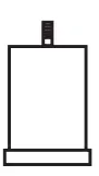 | 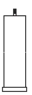 | 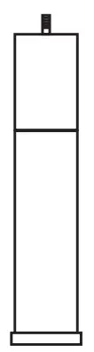 |  | |
| Bed Adjustable Height | 7.3” | 11” | 14.7” | 19.7” | |
Support leg may be needed on some slat/platform bed frames, refer to the leg configuration table for height adjustment.
* Make sure the adjustable legs are properly tight, and the plastic caps have been placed at the bottom of the legs. Incorrect installation might cause the part to fail or damage the floor.
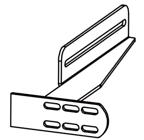
STABILIZERBRACKETS COMPONENTS | ||||
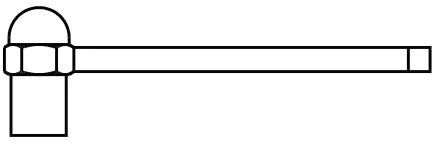
| (4) Stabilizer Brackets | (8) Screws ST4.2×16 | (8) Bolts M8*16 | (8)Washers | (1) Socket Wrench |
 |  |  | ||
Stabilizer Brackets are optional and not included. They can fix the bed onto the slat base. A phillips screwdriver and socket wrench are required to complete the installation.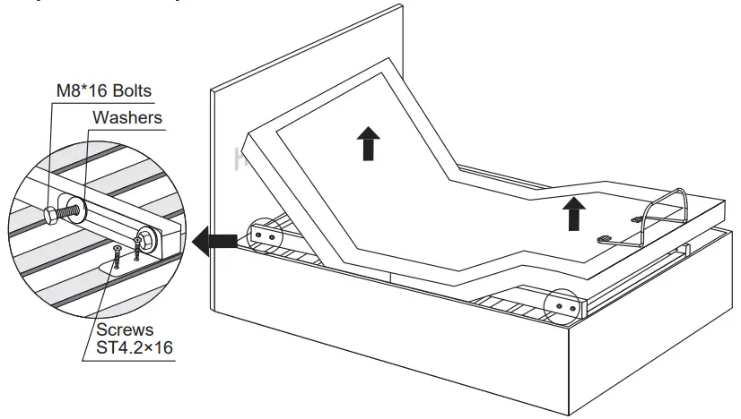
Lift the head and foot end of the bed by remote control. Install four stabilizer brackets as shown. Use a phillips screwdriver and socket wrench to tighten the screws and bolts.
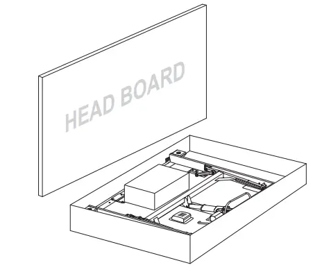
Headboard Bracket Installation Guide(Optional)
Headboard brackets are optional and not included. A 1/2” (13 mm) socket and 1/2” (13 mm) wrench are required to complete the installation
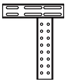
| HEADBOARD BRACKET COMPONENTS | ||||
| (2) Headboard Brackets | (2) T-Brackets | 8) M8*16 | (4) Nuts | (4) Washers |
 |  |  |  | |
| OPTIONAL EQUIPMENT/PART (NOT INCLUDED) | ||||
| ||||
STEP 1
a)Align the slot hole of the headboard bracket to the sleeve into 1 which the leg threads. DO NOT OVERTIGHTEN. Too much force may damage the thread.
b)The headboard bracket has 2 adjustable slots to accommodate any frame type. Use the bolts and washers to secure the bracket. Make sure the bolts are tight.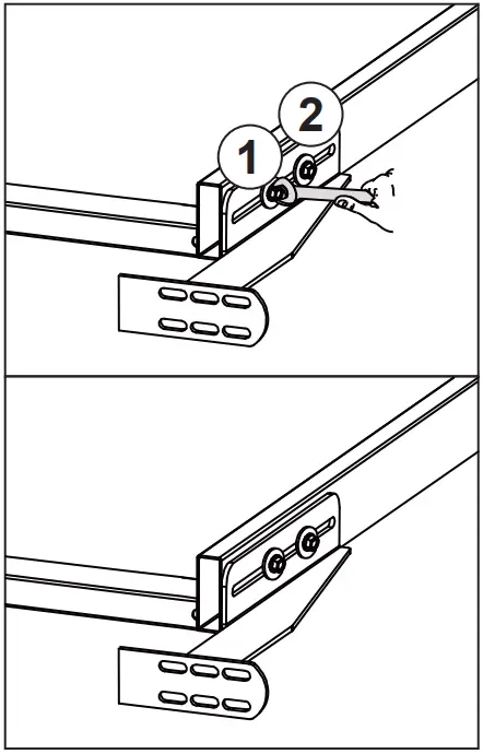
STEP 2
a)To put the T-Bracket and Headboard Bracket together, you will need (2) M8×16 bolts and (2) nuts. Slip the bolts through the holes from T-Bracket to Headboard Bracket with the head of bolt facing outward. Use the 1/2” (13 mm) socket and 1/2” (13mm) wrench to tighten the bolts.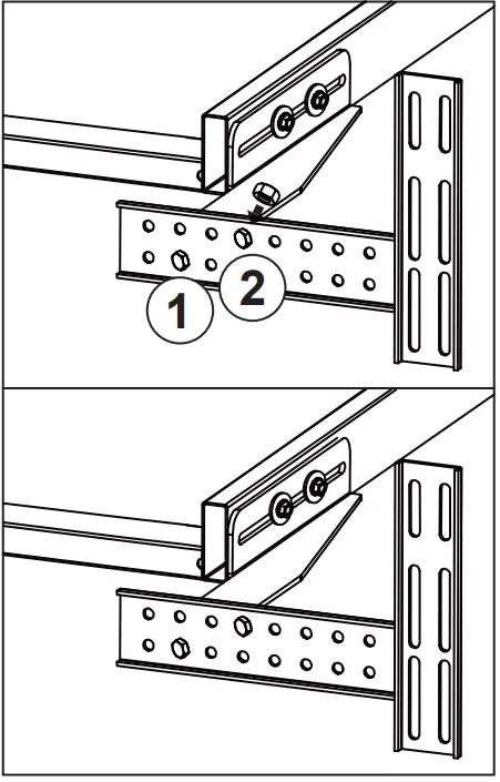
STEP 3
You may now connect your headboard to the attachment plates using the remaining short bolts and nuts to secure it to the brackets. The heads of the bolts will face outward. Use a 1/2” (13mm) socket and 1/2” (13mm) wrench to tighten the bolts.
MotoSleep Mobile APP(Optional)
General Information
MotoSleep Mobile APP is a mobile application to control the MotoSleep Power Foundation with mobile devices. The application is available for both iOS and Android based smart devices. The MotoSleep Mobile APP uses the latest technology to communicate with your MotoSleep Power Foundation. Make sure your mobile devices has the pairing function for the APP to work correctly.
Install the MotoSleep APP
IOS


- Open APP Store on your IOS device
- Tap the Magnify Glass Icon
 and search with the keyword
 - Tap on GET and INSTALL to install the APP
- Wait for the download/installation to be complete
Android

- Open www.motosleep.com from your browser.
- Scroll down to the bottom of the page and press download
- In the download page, tap the download button to download the app.
- Open the download file and install the app.
The Built-in Owner’s Manual at your fingertip
Device Pairing
Before you start. Switch on the pairing function on your mobile device. Make sure your MotoSleep Power Foundation is correctly connected and is power-on.
The MotoSleep APP will automatically pair your MotoSleep Power Foundation once you start the APP and does not require additional settings.
MotoSleep APP Home Screen
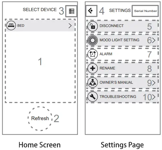
| Home Screen | |
1 | List of MotoSleep Products within the connection range* |
2 | Tap the Refresh Button to refresh the MotoSleep Products List |
3 | Enter the Settings Page |
| Settings Page | |
4 | Back to the Home Screen |
5 | Disconnect from the paired MotoSleep Product |
6 | Choose the light colors, and set up the motion sensor timer |
7 | Set the alarm time |
8 | Rename your MotoSleep Power Foundation of your choice |
9 | Owner’s Manual Page |
10 | Troubleshooting |
11 | Serial Number of the control box |
* The effective connection range is ± 10m
MotoSleep APP Remote Control
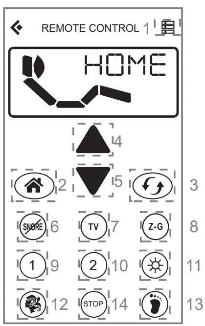
* Remote interface varies in between different MotoSleep Power Foundation models. If you wish to disconnect from the current paired Power Foundation, Enter the Settings Page and tap the Disconnect button.
Remote Control | |
1 | Enter the Settings Page |
2 | One touch flat position |
3 | Select Head, Foot, Neck or Lumbar section |
4 | Lifting function |
5 | Lowering function |
6 | Anti-Snore Preset Position |
7 | TV Position |
8 | Zero G Preset Position |
9 | Programmable Position 1 |
10 | Programmable Position 2 |
11 | Under Bed Lighting |
12 | Head Massage (3 different intensities) |
13 | Foot Massage (3 different intensities) |
14 | Massage Off Button |
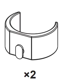
Spacing Connector for TXL/T/CKS (Optional)
Install two spacing connectors to ensure the gap between the two adjustable bases is consist
| (2) SPACING CONNECTOR (TXL/T/CKS ONLY) |
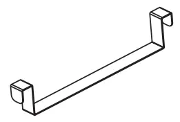 |
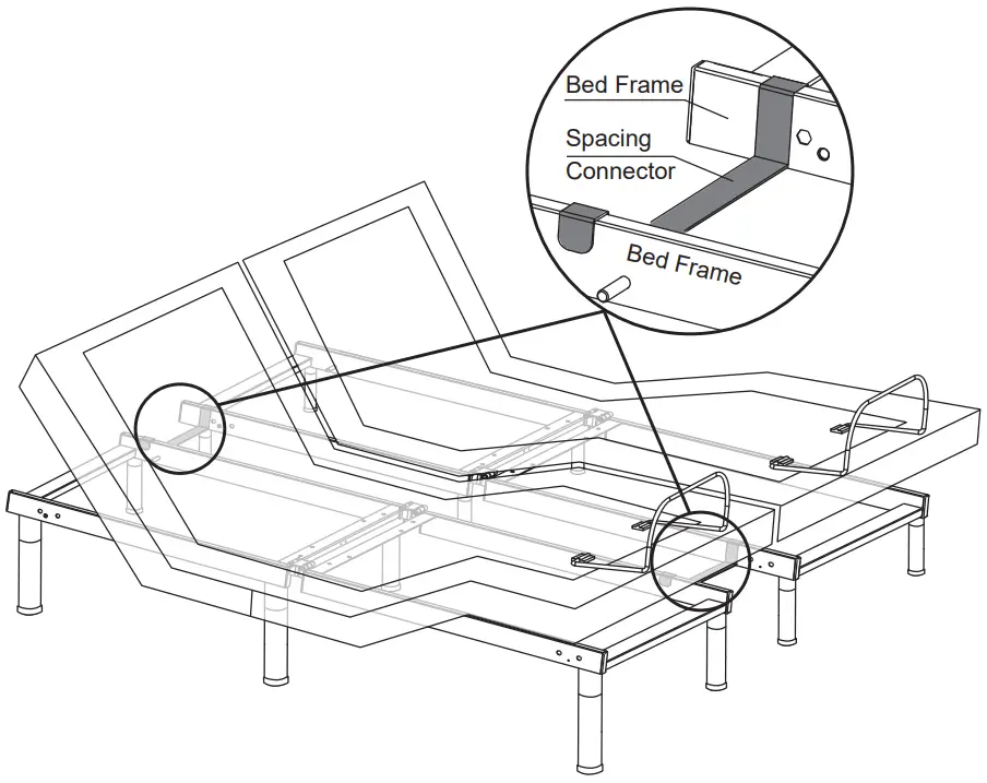
Lift the head and foot end of the bed by remote control. Install the spacing connector as shown.
Audio System
Pairing Instruction
- Once power is supplied, the audio kit begins to search pairing device automatically. It keeps searching until it pairs with other device successfully. It could only pair with one device at a time. If you want to pair with a different device, disconnect the paired device, before connect with the new device.
- The audio kit could be controlled via the paired device.
- Description of device:REMO4.11
- Connection rang: 26 ft.
Frequently Asked Questions
| Description of problem | Possible cause, correction & maintenance |
| No sound | The volume is on minimum; Audio System not paired properly; Please contact the store or customer service. |
| Audio System cannot be paired | Restart your power base; Do not attempt to pair the device behind a wall; Make sure you’re pairing the device within the working distance (26 ft). |
TOOLS REQUIRED: NO TOOLS REQUIRED | ||||
PART LIST | ||||
| NO | Description | Sketch | Quantity | Remark |
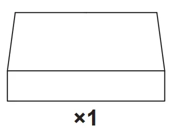
A | PSFAB350FM | 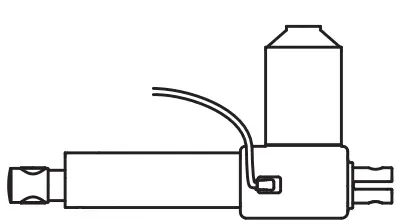 | 1 | |
B | PSFAB350HM | 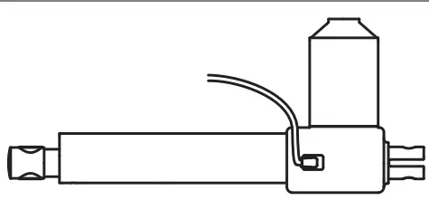 | 1 | |
C | PSFAB350UA | 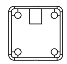 | 1 for TXL 2 for Q/K | |
D | PSFAB350UCS | 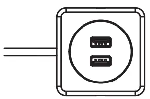 | 1 for TXL 2 for Q/K | |
| E | PSFAB350NM | 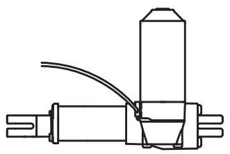 | 1 | |
F | PSFAB350LM | 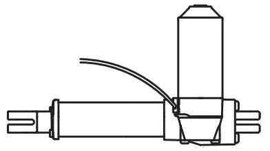 | 1 | |
G | PSFAB350CB | 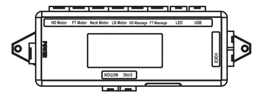 | 1 | |
H | PSFAB350PL | 1 | ||
I | PSFAB350PB | 1 | ||
J | PSFAB350R | 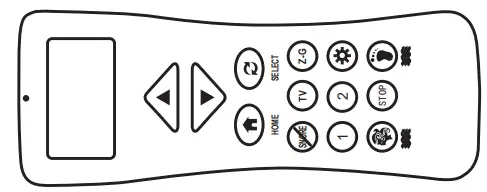 | 1 | |
K | PSFAB350LTXL | 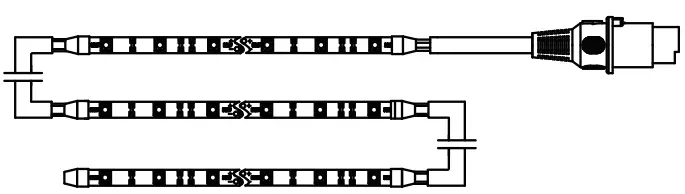 | 1 | For TXL |
L | PSFAB350LQ | 1 | For Q | |
M | PSFAB350LK | 1 | For K | |
N | PSFAB350MMR | 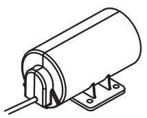 | 1 | For TXL/Q |
O | PSFAB350MMHD | 1 | For TXL/Q | |
p | PSFAB350MMB | 4 | For K | |
Q | PSFAB350MS |  | 2 | |
Customer Service Toll Free:1-844-696-6886


