 CARLO GAVAZZI Energy Meter
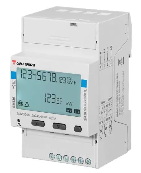
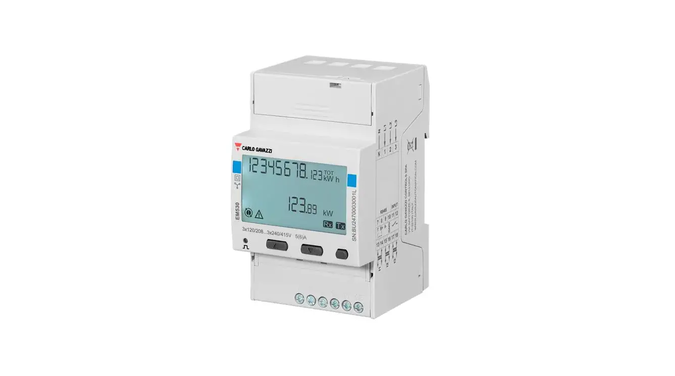
EM530/EM540 Energy Analyzer
The EM530/EM540 energy analyzer is a device used for analyzing three-phase and two-phase systems. The analyzer has both two and three-phase system options. The EM530 model is connected through 5A current transformers, while the EM540 model is for direct connection up to 65 A. Both models have a digital input and can be equipped, depending on the model, with a static output (pulse or alarm), a Modbus RTU communication port or an M-Bus communication port.
Product Usage Instructions
To use the EM530/EM540 Energy Analyzer, follow these steps:
Commissioning
- Perform preliminary settings for the analyzer using the MID SETTINGS menu or QUICK SETUP menu.
- Select the appropriate settings from the SETTINGS menu.
- View information from the INFO menu.
- Reset settings as necessary using the RESET menu.
Working with Measurement Pages
The analyzer has measurement pages displayed on the screen. To work with these pages:
- Select the required measurement page from the home page.
- Scroll through the page using the PAGE FILTER function if needed.
Input, Output, and Communication
The EM530/EM540 Energy Analyzer has a digital input, digital output (version O1), Modbus RTU port (version S1), and M-Bus port (version M1) options. To use these functionalities, follow the instructions provided in the manual.
Restoring Factory Settings
To restore factory settings:
- Select the restore options from the RESET menu.
- Restore the MID menu using the RESET menu if needed.
Tariff Management
The analyzer has a tariff management function available via digital input or Modbus RTU communication. Follow the instructions provided in the manual to use this functionality.
Maintenance and Disposal
The analyzer requires regular cleaning to avoid damage. For disposal, follow local regulations.
It is important to note that unauthorized opening of the analyzer is strictly prohibited and may lead to impaired protection. In case of malfunction or faults, contact the manufacturer’s technical service personnel.
This manual
Information property
Copyright © 2023, CARLO GAVAZZI Controls SpA
All rights reserved in all countries.
CARLO GAVAZZI Controls SpA reserves the right to apply modifications or make improvements to the relative documentation without the obligation of advance notice.
Safety messages
The following section describes the warnings related to user and device safety included in this document: NOTICE: indicates obligations that if not observed may lead to damage to the device.
CAUTION! Indicates a risky situation which, if not avoided, may cause data loss.
IMPORTANT: provides essential information on completing the task that should not be neglected.
General warnings
This manual is an integral part of the product and accompanies it for its entire working life. It should be consulted for all situations tied to configuration, use and maintenance. For this reason, it should always be accessible to operators.
NOTICE: no one is authorized to open the analyzer. This operation is reserved exclusively for CARLO GAVAZZI technical service personnel.
Protection may be impaired if the instrument is used in a manner not specified by the manufacturer.
Service and warranty
In the event of malfunction, fault, requests for information or to purchase accessory modules, contact the CARLO GAVAZZI branch or distributor in your country.
Installation and use of analyzers other than those indicated in the provided instructions void the warranty.
Introduction
EM530 is an energy analyzer connected through 5 A current transformers, for two- and three-phase systems up to 415 V L-L. EM540 is an energy analyzer for direct connection up to 65 A, for two- and three-phase systems up to 415 V L-L.
In addition to a digital input, the unit can be equipped, according to the model, with a static output (pulse or alarm), a Modbus RTU communication port or an M-Bus communication port.
Description
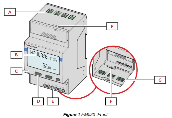
| Area | Description |
| A | Voltage inputs |
| B | Display |
| C | LED |
| D | Browsing and configuration buttons |
| E | Digital input, digital output and communication connections |
| F | MID seal housings |
| G | Current inputs |
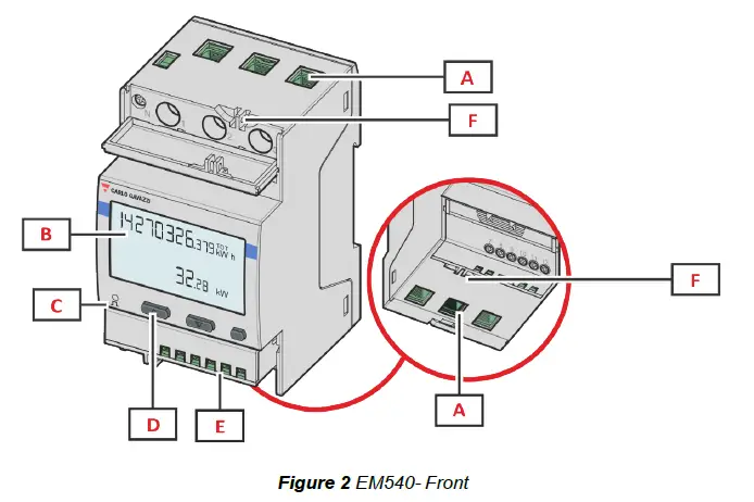
| Area | Description |
| A | Voltage/current inputs |
| B | Display |
| C | LED |
| D | Browsing and configuration buttons |
| E | Digital input, digital output and communication connections |
| F | MID seal housings |
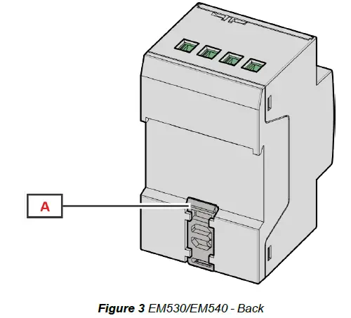
| Area | Description |
| A | DIN rail mounting bracket |
Available versions
| Part number | Connection | Output | MID approval | cULus approval |
| EM530DINAV23XO1X | Via CT (5A secondary output) | Digital output | x | |
| EM530DINAV23XS1X | Via CT (5A secondary output) | RS485 Modbus RTU | x | |
| EM530DINAV23XM1X | Via CT (5A secondary output) | M-Bus | x | |
| EM530DINAV23XO1PFA EM530DINAV23XO1PFB EM530DINAV23XO1PFC | Via CT (5A secondary output) | Digital output | x | |
| EM530DINAV23XS1PFA EM530DINAV23XS1PFB EM530DINAV23XS1PFC EM530DINAV23XS1PFA70 EM530DINAV23XS1PFB70 EM530DINAV23XS1PFC70 | Via CT (5A secondary output) | RS485 Modbus RTU | x | |
| EM530DINAV23XM1PFA EM530DINAV23XM1PFB EM530DINAV23XM1PFC | Via CT (5A secondary output) | M-Bus | x |
| Part number | Connection | Output | MID approval | cULus approval |
| EM540DINAV23XO1X | Direct connection up to 65 A | Digital output | x | |
| EM540DINAV23XS1X | Direct connection up to 65 A | RS485 Modbus RTU | x | |
| EM540DINAV23XM1X | Direct connection up to 65 A | M-Bus | x | |
| EM540DINAV23XO1PFA EM540DINAV23XO1PFB EM540DINAV23XO1PFC | Direct connection up to 65 A | Digital output | x | |
| EM540DINAV23XS1PFA EM540DINAV23XS1PFB EM540DINAV23XS1PFC EM540DINAV23XS1PFA70 EM540DINAV23XS1PFB70 EM540DINAV23XS1PFC70 | Direct connection up to 65 A | RS485 Modbus RTU | x | |
| EM540DINAV23XM1PFA EM540DINAV23XM1PFB EM540DINAV23XM1PFC | Direct connection up to 65 A | M-Bus | x |
PFA models
Easy connection function: irrespective of the current direction, the power always has a plus sign and contributes to increasing the positive energy meter. The negative energy meter is not available.
PFB models
For each measuring time interval, the individual phase energies with a plus sign are summed to increase the positive energy meter (kWh+), while the others increase the negative one (kWh-).
Example:
P L1= +2 kW, P L2= +2 kW, P L3= -3 kW
Integration time = 1 hour
kWh+ = (2+2) x1h = 4 kWh
kWh- = 3 x 1h= 3kWh
PFC models
For every measuring interval time, the energies of the single phases are summed; according to the sign of the result, the positive (kWh+) or negative totalizer (kWh-) is increased.
Example:
P L1= +2 kW, P L2= +2 kW, P L3= -3 kW
Integration time = 1 hour
kWh+=(+2+2-3)x1h=(+1)x1h=1 kWh
kWh+=0 kWh
UCS (Universal Configuration Software)
UCS is available in desktop and mobile versions.
It may connect to EM530 or EM540 via RS485 (RTU protocol, desktop version only). UCS allows to:
- set up the unit (online or offline);
- display the system state for diagnostic and setup verification purposes
Overview of the UCS functions:
- Setting up the system with energy meter connected (online setup)
- Defining the setup with energy non connected, then applying it later (offline setup)
- Displaying the main measurements
- Displaying the state of inputs and outputs
- Displaying the state of the alarms
- Recording the measurements of selected variables
- Check connection and correct wiring errors
Use
Interface
Introduction
EM530/EM540 is organized into two menus:
- Measurement pages: pages allowing to display the energy meters and the other electrical variables
- Main menu, divided into three sub-menus:
- » SETTINGS: pages allowing to set the parameters
- » INFO: pages displaying general information and the set parameters
- » RESET: pages allowing to reset the partial counters and the dmd calculation, or to restore the factory settings
SETTINGS menu display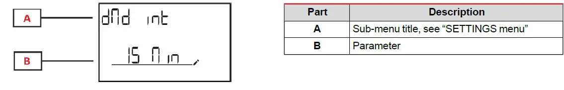
INFO menu display
RESET menu display
Measurement page display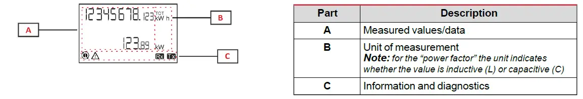
Information and warnings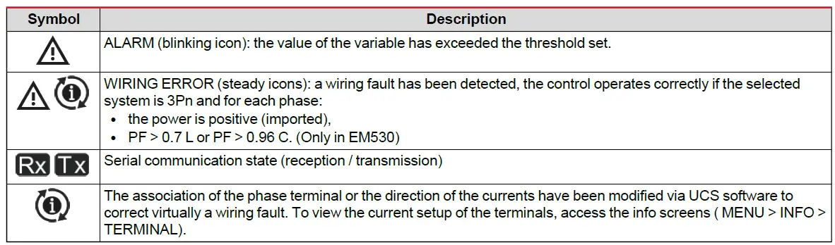
Working with EM530/EM540
Working with the measurement pages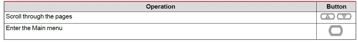
Working with the SETTINGS menu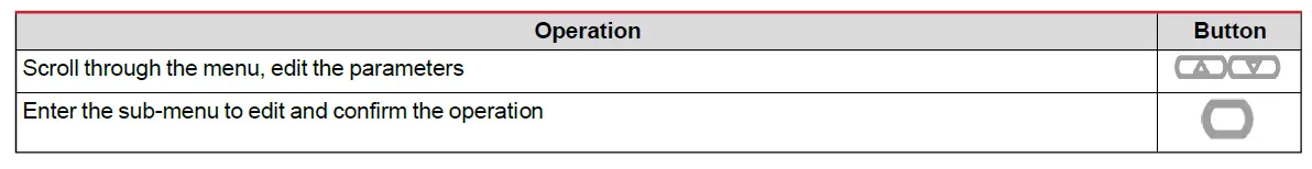
Working with the INFO menu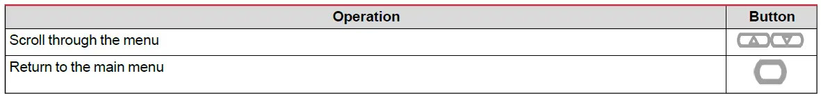
Working with the RESET menu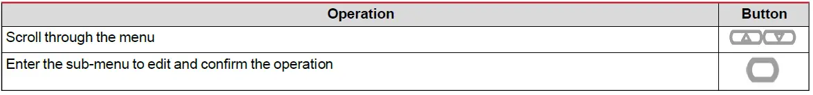
Commissioning
Preliminary settings
At switch-on, the device displays two preliminary setting menus:
- MID SETTINGS, for EM530, MID models only
- QUICK SETUP
MID SETTINGS menu
This procedure, only available in MID models, allows programming the current transformer ratio (CT ratio).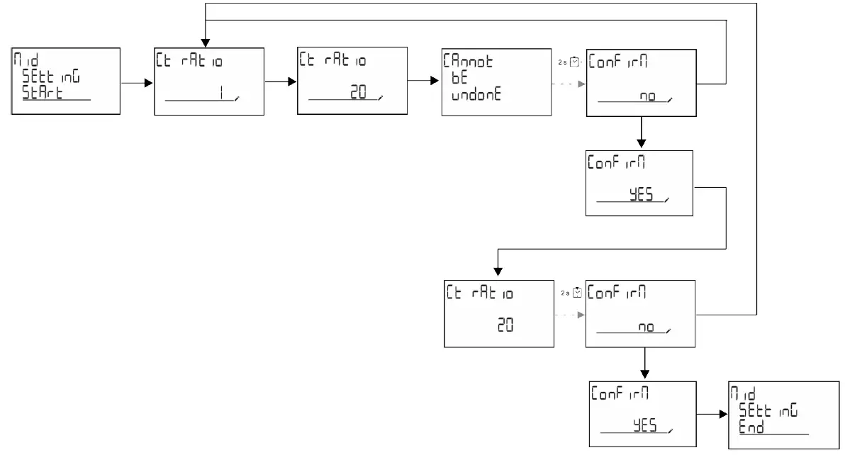
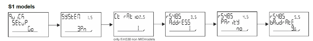
QUICK SETUP menu
This procedure is available when the instrument is switched on for the first time.
Note: the available parameters depend on the model. In the “QUICK SETUP?” starting page
| Select… | To… |
| Go | run the QUICK SETUP procedure |
| no | skip the procedure and no longer display the QUICK SETUP menu |
| LAtEr | skip the procedure and display the QUICK SETUP menu at the next switch-on |
Measurement pages
The displayed pages depend on the selected system.
| Page | Displayed measurements | Description |
| 1 | kWh+ TOT kW | Imported active energy (TOTAL) System active power |
| 2 | kWh- TOT kW | Exported active energy (TOTAL) System active power |
| 3 | kWh+ TOT kWh+ PAR kW | Imported active energy (TOTAL) Imported active energy (PARTIAL) System active power |
| 4 | kWh+ TOT kW PF | Imported active energy (TOTAL) System active power System power factor |
| 5 | VLN VLL Hz | System line-line voltage System line-neutral voltage Frequency |
| 6 | kWh+ TOT kW kW sys DMD P | Imported active energy (TOTAL) System active power Peak demand System active power |
| 7 | kvarh TOT kvar | Imported reactive energy (TOTAL) System reactive power |
| 8 | kvarh- TOT kvar | Exported reactive energy (TOTAL) System reactive power |
| 9 | kVAh TOT kW kVA | Apparent energy (TOTAL) System active power System apparent power |
| 10 | kWh TOT h TOT kW | Imported active energy (TOTAL) Run hour meter (kWh+) TOTAL System active power |
| 11 | kWh- TOT h- TOT kW | Exported active energy (TOTAL) Run hour meter (kWh-) TOTAL System active power |
| 12 | kWh PAR h PAR kW | Imported active energy (PARTIAL) Run hour meter (kWh+) PARTIAL System active power |
| 13 | kWh- PAR h- PAR kW | Imported active energy (PARTIAL) Run hour meter (kWh-) PARTIAL System active power |
| 14 | kWh+ TOT kWh T1 kW | Imported active energy (TOTAL) Imported active energy tariff 1 System active power |
| 15 | kWh+ TOT kWh T2 kW | Imported active energy (TOTAL) Imported active energy tariff 2 System active power |
| 16 | Thd Ln | THD of phase 1 voltage THD of phase 2 voltage THD of phase 3 voltage |
| 17 | Thd LL | THD of phase 1-phase2 voltage THD of phase2-phase3 voltage THD of phase3-phase1 voltage |
| 18 | Thd A | THD of phase 1 current THD of phase 2 current THD of phase 3 current |
| 19 | nEutrAL CurrEnt | Neutral current |
| Page | Displayed measurements | Description |
| 20 | L1 kVA L2 kVA L3 kVA | Phase 1 apparent power Phase 2 apparent power Phase 3 apparent power |
| 21 | L1 kvar L2 kvar L3 kvar | Phase 1 reactive power Phase 2 reactive power Phase 3 reactive power |
| 22 | L1 PF L2 PF L3 PF | Phase 1 power factor Phase 2 power factor Phase 3 power factor |
| 23 | L1-N V L2-N V L3-N V | Phase 1 voltage Phase 2 voltage Phase 3 voltage |
| 24 | L1-2 V L2-3 V L3-1 V | Phase 1-phase 2 voltage Phase 2-phase 3 voltage Phase 3-phase 1 voltage |
| 25 | L1 A L2 A L3 A | Phase 1 current Phase 2 current Phase 3 current |
| 26 | L1 kW L2 kW L3 kW | Phase 1 active power Phase 2 active power Phase 3 active power |
| 27 | L1 kWh TOT L2 kWh TOT L3 kWh TOT | Active energy phase 1 Active energy phase 2 Active energy phase 3 |
SETTINGS menu
This menu allows to set the parameters.
| Page title | Sub-menu | Description | Values | Default values | Note |
| SYSTEM | – | System | 3P+N 3P 2P | 3P+N | |
| CT RAT | – | (CT) current transformer ratio | 1 to 2000 | 1 | Non-MID, AV5 models only |
| MEASurE | – | Measurement mode | A B C | A | Non-MID models only |
| dMd int | – | DMD interval | 1 min 5 min 10 min 15 min 20 min 30 min 60 min | 15 min | |
| inPut | Function | Digital input function | Tariff: tariff management Status: remote status P reset: partial meters reset P StArt: partial meter start/stop | Status | |
| RS485 | AddrESS | Address | 1 to 247 | 1 | S1 models only |
| PArity | Parity | NO/EVEN | no | ||
| bAudrAtE | Baudrate | 9.6 kbps 19.2 kbps 38.4 kbps 57.6 kbps 115.2 kbps | 9.6 kbps | ||
| StoP bit | Stop bit | 1 or 2 | 1 |
| Page title | Sub-menu | Description | Values | Default values | Note |
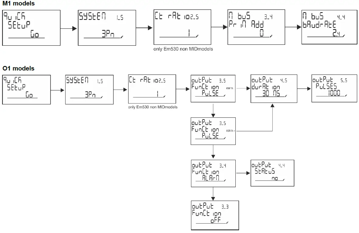
| M bus | Pri Add | Primary address | 1 to 250 | 0 | M1 models only |
| bAudrAtE | Baudrate | 0.3 kbps 2.4 kbps 9.6 kbps | 2.4 kbps | ||
| Output | Function | Function | Off PuLSE (kWh+): pulse output linked to kWh+ PuLSE (kWh-): pulse output linked to kWh- ALArM: linked to alarm status | PuLSE (kWh+) | O1 models only |
| durAtion | Pulse duration | 30 ms 100 m | 30 ms | ||
| PuLSES | Pulse weight (pulses/kWh) | 0.1/1/10/100/500/1000 | 1000 | ||
| StAtuS | Output status | No (normally open) Nc (normally closed) | |||
| ALARM | EnAbLE | Enable | YES/no | no | |
| VAriAbLE | Monitored variable | kW A V L-N V L-L PF Kvar kVA | kW | ||
| SEt 1 | Activation threshold | -15000 to 15000 | 0.00 | ||
| Set 2 | Deactivation threshold | -15000 to 15000 | 0.00 | ||
| dELAY | Activation delay | 0 to 3600 s | 0 | ||
| dISPLAY | LiGHt | Timer for backlight switch-off | On: always on 1 min 2 min 5 min 10 min 15 min 30 min 60 min oFF: always off | On | |
| SC SAVEr | Screensaver enabling, see “Screensaver” on page 22 | oFF SLidE: slideshow home: homepage | home | Non-MID models only | |
| HOME | homepage | 1 to 27 | 1 | Non-MID models only | |
| PAGES | Measurement page filter enabling, see “Page filter” on page 22 | ALL FiLtEr | OFF | ||
| WirinG | Wiring check enabling | on/OFF | on | ||
| PASS | Password enabling for the SETTINGS and RESET menu | 0 (not protected) to 9999 | 0 (NOT PROTECTED) | ||
| End | – | Exit | – | – |
INFO menu
This menu allows to display the set parameters.
| Page | Page title | Description | Notes |
| 1 | YEAr | Production year | |
| 2 | SEriAL n | Serial number | |
| 3 | FW REV | FW revision |
| Page | Page title | Description | Notes |
| 4 | Led PuLS | LED pulse weight | |
| 5 | SyStEM | Electrical system | |
| 6 | Ct rAtio | CT ratio | EM530 only |
| 7 | MEAsurE | Measurement type | |
| 8 | dMd int | Demand calculation interval | |
| 9 | Input Function | Digital input function | |
| 10 | rS 485 AddrESS | Address | S1 versions only |
| 11 | rS485 bAudrAtE | Baudrate (kbps) | S1 versions only |
| 12 | rS485 PArity | Parity | S1 versions only |
| 13 | rS485 StoP bit | Stop bit | S1 versions only |
| 14 | M buS PriM Add | M-Bus primary address | M1 versions only |
| 15 | M bus bAudrAte | M-Bus baudrate | M1 versions only |
| 16 | M bus SEC Add | M-Bus secondary address | M1 versions only |
| 17 | output Function | Digital output function | O1 versions only |
| 18 | Output StAtuS | Current output status | O1 versions only |
| 19 | output duration | Pulse output duration | O1 versions only |
| 20 | Output PuLSE | Output pulse weight | O1 versions only |
| 21 | ALArM EnAbLe | Alarm enabling | |
| 22 | ALArM VAriAbLE | Linked variable | |
| 23 | ALArM SEt 1 | Alarm activation set point | |
| 24 | ALArM SEt 2 | Alarm deactivation set point | |
| 25 | ALArM dELAY | Alarm activation delay | |
| 26 | display LIGHt | Backlight timer | |
| 27 | display SC SAVEr | Screensaver type | |
| 28 | display home | Home page | |
| 29 | display PAGES | Page filter enabling | |
| 30 | display WirinG | Wiring check enabling | |
| 31 | tAriFF | Tariff management | |
| 32 | CHECKSuM | Firmware checksum | |
| 33 | WiRinG | Wiring check code to correct errors |
| Page | Page title | Description | Notes |
| 34 | terminal | Screw terminal phase assignment (press enter to see) | |
| 35 | On time | Total working time | |
| 36 | End | Exit |
RESET menu
This menu allows to reset the following settings:
| Page | Page title | Description |
| 1 | PArtiAL | It resets the partial meters |
| 2 | DMD | It resets the dmd calculation |
| 3 | tAriFF | It restores the factory settings |
| 4 | total | It resets the total meters (only non-MID) |
| 5 | FACtorY | It resets the device to factory settings. In the case of MID models, all parameters are restored except the CT ratio. |
| 6 | MID ReS | In MID models, it resets the CT ratio settings re-enabling first programming menu. This option is available only if the value of the total active energy is below 1 kWh. |
| 7 | End | Exit |
Input, output and communication
Digital input
The digital input can perform four functions:
| Function | Description | Parameters | |
| Tariff management | Digital input used to manage the tariff | – | |
| Digital input status | Tariff | ||
| Open | Tariff 1 | ||
| Closed | Tariff 2 | ||
| Remote status | Digital input is used to check the status via Modbus or M-Bus. | – | |
| Digital input status | Register 300h | ||
| Open | 0 | ||
| Closed | 1 | ||
| Partial meters start/stop | Digital input is used to enable/disable the reset of partial meters | – | |
| Digital input status | Partial meter | ||
| Open | Disabled (in pause) | ||
| Closed | Enabled | ||
| Partial meter reset | Digital input is used to enable/disable the increasing of partial meters | – | |
| Digital input status | Action | ||
| Open | No action | ||
| Closed | After 3 seconds, reset partial meters | ||
Digital output (version O1)
The digital output can perform two functions:
| Function | Description | Parameters |
| Alarm | Output associated with the alarm | Output state when no alarm is active |
| Pulse output | Pulse transmission output for imported active energy consumptions. | l Linked energy (kWh+, kWh-) l Pulse weight l Pulse duration |
Modbus RTU port (version S1)
Modbus RTU communication port is used to transmit data to a Modbus master (Carlo Gavazzi UWP3.0 or any SCADA, PLC, BMS, etc).
For further information about Modbus RTU communication refer to the communication protocol.
M-Bus port (version M1)
M-Bus communication port is used to transmit data to a M-Bus master (Carlo Gavazzi SIU-MBM or any third party M-Bus master). For further information about M-Bus communication refer to the communication protocol.
Essential information
Alarms
Introduction
EM500 manages a measured variable alarm. To set the alarm, define:
- the variable to be monitored (VARIABLE)
- alarm activation threshold value (SET POINT 1)
- alarm deactivation threshold value (SET POINT 2)
- alarm activation delay (ACTIVATION DELAY)
Variables
The unit can monitor one of the following variables:
- system active power
- system apparent power
- system reactive power
- system power factor
- phase-neutral voltage (OR logic)
- phase-phase voltage (OR logic)
- current (OR logic)
Note: if you select a current or a voltage, the analyzer simultaneously monitors all the phases available in the set measurement system and triggers the alarm when at least one of the phases is in alarm (OR logic)
Alarm types
Up alarm (Set point 1 ≥ Set point 2)
The alarm activates when the monitored variable exceeds the Set 1 value for a time equal to the activation delay (Delay) and deactivates when the values drops below Set 2.
Down alarm (Setpoint 1 < Setpoint 2)
The alarm activates when the monitored variable drops below the Set 1 value for a time equal to the activation delay (Delay) and deactivates when it exceeds Set 2.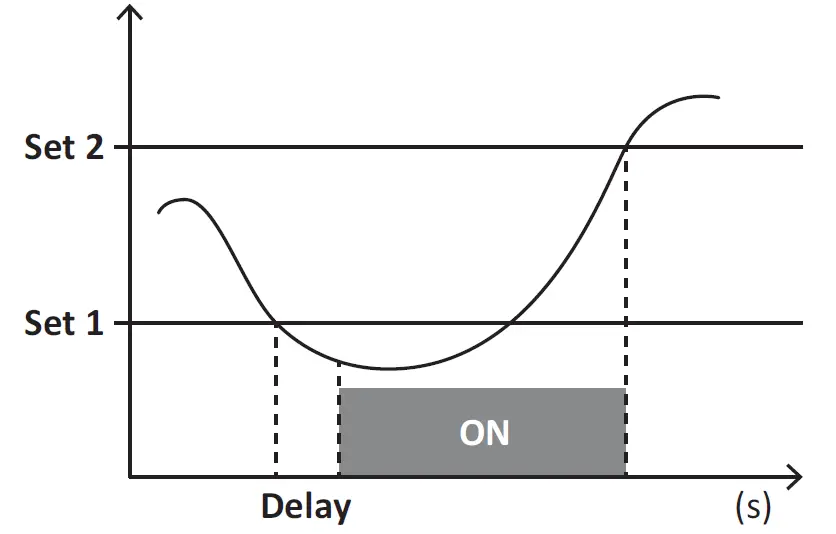
DMD values
Average value calculation (dmd)
EM530/EM540 calculates the average values of the electrical variables within a set integration interval (15 min by default).
Integration interval
The integration interval starts at switch-on or when the reset command is issued. The first value is displayed at the end of the first integration interval.
Example
The following is a sample integration:
- reset at 10:13:07
- set integration time: 15 min.
The first value displayed at 10:28:07 refers to the interval from 10:13:07 to 10:28:07.
LCD display
Home page
The unit may display the default measurement pages after no operation has been performed for five minutes if the screensaver is enabled and the screensaver type is as “Home page” (default value).
Notes: if you select a page that is not available in the set system, the unit displays as its home page the first available page. In MID models the home page cannot be changed and displays the active energy meter.
Backlight
EM530/EM540 is equipped with a backlight system. You can set whether the backlight shall always be ON or whether it should automatically switch off after a given interval has elapsed since a button was pressed (1 to 60 minutes).
Screensaver
If the SCREENSAVER function is enabled (default setting), after 5 minutes have elapsed since a button was pressed the unit will display the home page if the screensaver type is “Home page” (default setting), or it shall activate the slideshow function, which displays the selected pages on a rotating basis.
Notes: In MID models the screensaver setting is “Homepage” and cannot be changed.
Page filter
The page filter makes it easier to use and browse the measurement pages. When you use the buttons, the unit shall only display the pages you are most interested in, which can be selected through the UCS software (S1 version) or is pre-defined (O1 and M1 version)
Note: to display all the pages without using the UCS software, you can disable the page filter from the SETTINGS MENU
(DISPLAY → PAGES→ ALL). By default, the pages included in the filter are: 1 (kWh+ TOT, kW), 2 (kWh- TOT, kW), 5 (VLN, VLL, Hz), 7 (kvarh+ TOT, kvar), 8 (kvarh- TOT, kvar), 25 (L1 A, L2 A, L3 A), see “Measurement pages” on page 14.
Restoring the factory settings
Restoring the settings using the RESET menu
From the RESET menu you can restore all the factory settings. At start-up the QUICK SET-UP menu shall be available again.
Notes: meters are not reset. In MID models you cannot reset the CT current transformer ratio (CT RATIO).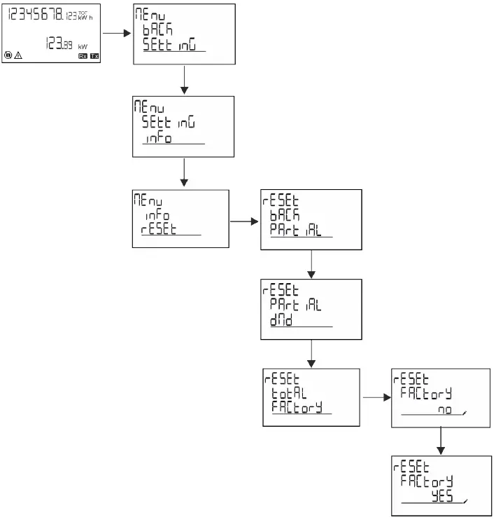
Restoring the MID menu using the RESET menu
To change the set CT ratio and restore the MID settings menu shown at first power on EM530 MID models, enter the reset menu and confirm “MID res”.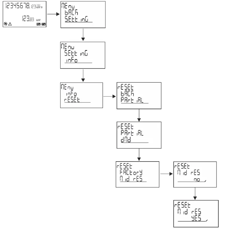
Note: in MID models the reset can only be performed if the energy meter has not exceeded 1 kWh. In case of wrong settings, you can then correct any CT current transformer setting errors (CT ratio), reactivating the MID programming menu.
Notes: if active energy has exceeded 1 kWh, the CT ratio cannot be changed.
WIRING CHECK function
Introduction
The WIRING CHECK function allows to check and correct the connections. For it to work properly, the following three conditions must be met:
- the set system must be “3P+N”,
- all voltages must be connected,
- All currents must be greater than zero, with an offset ranging between a 45° lag and a 15° lead (power factor > 0.7 inductive or > 0.96 capacitive)
Display check
During operation, if a wiring error is detected the alarm icon will light up.
If the three conditions fail to be met, the following indications shall be displayed in the WIRING info page:
- V MISSING: at least one voltage is missing
- I MISSING: at least one current is missing
- PF OUT OF RANGE: the current-voltage offset is out of range.
Check from UCS software
By connecting to the analyzer through the UCS software or UCS Mobile, you can verify the connections and perform the steps required to correct the wiring error.
Virtual correction from UCS software or UCS Mobile
The virtual correction function allows to calculate the wiring error solution and to modify the association of the physical connections with the measurement references.
Example
if the connections of terminals 5 and 6 are inverted (voltage 2 and voltage 3), by accepting the proposed solution, voltage 2 shall be the one measured with reference to terminal 6, while voltage 3 shall be the one referring to terminal 5.
The unit shall display the icon, signalling that the association was modified via software and referring to the info pages to check the phase-terminal associations set by UCS. Note: the function is not available in MID models
Tariff management
Tariff management via digital input
To manage tariffs using the digital input set the function of the digital input as tariff (via keypad or UCS software). The current tariff depends on the status of the input
| Digital input status | Tariff |
| Open | Tariff 1 |
| Closed | Tariff 2 |
Tariff management Modbus RTU
To manage tariffs using the Modbus RTU command enable tariff management via Modbus command from UCS software
| Digital input status | Tariff |
| 0 | No tariff |
| 1 | Tariff 1 |
| 2 | Tariff 2 |
Maintenance and disposal
Troubleshooting
Note: in case of other malfunctions or of any failure, please contact the CARLO GAVAZZI branch or the distributor for your country
| Problem | Cause | Possible solution |
| The ‘EEEE’ indication is displayed instead of a measurement | The analyser is not used within the prescribed measuring range; as a consequence, the measurement exceeds the maximum permitted value or is the result of a calculation with at least one measurement in error. | Uninstall the analyser |
| The analyser has just been switched on and the interval defined for the calculation of the average power values (default: 15 min) has not expired yet. | Wait. If you wish to change the interval, access the Dmd page of the Settings menu | |
| The displayed values are not the expected ones | Electrical connections are incorrect | Verify the connections |
| The current transformer settings are incorrect | Check the set current transformer ratio |
Alarms
| Problem | Cause | Possible solution |
| An alarm is triggered, but the measurement has not exceeded the threshold value | The value with which the alarm variable is calculated is in error | Check the set current transformer parameters |
| The alarm is not activated and deactivated as expected | The alarm settings are incorrect | Check the set parameters |
Communication problems
| Problem | Cause | Possible solution |
| No communication can be established with the analyser | Communication settings are incorrect | Check the set parameters |
| Communication connections are incorrect | Verify the connections | |
| The settings of the communication device (third-party PLC or software) are incorrect | Check the communication with the UCS software |
Display problem
| Problem | Cause | Possible solution |
| You cannot display all measurement pages | The page filter is enabled | Disable the filter, see “Page filter” on page 22 |
Download
| This manual | https://www.gavazziautomation.com/images/PIM/MANUALS/ENG/EM500_IM_USE_ENG.pdf |
| EM530 installation manual | https://gavazziautomation.com/images/PIM/MANUALS/ENG/EM530_IM_INST.pdf |
| EM530 datasheet | https://gavazziautomation.com/images/PIM/DATASHEET/ENG/EM530_DS_ENG.pdf |
| EM540 installation manual | https://gavazziautomation.com/images/PIM/MANUALS/ENG/EM540_IM_INST.pdf |
| EM540 datasheet | https://gavazziautomation.com/images/PIM/DATASHEET/ENG/EM540_DS_ENG.pdf |
| UCS desktop | www.productselection.net/Download/UK/ucs.zip |
| UCS Mobile | Google Play Store |
Cleaning
To keep the display clean, use a slightly wet cloth. Never use abrasives or solvents.
Responsibility for disposal
Dispose of the unit by separately collecting its materials and bringing them to the facilities specified by government authorities or by local public bodies. Proper disposal and recycling will help preventing potentially harmful consequences for the environment and for people.
via Safforze, 8
32100 Belluno (BL) Italy
www.gavazziautomation.com [email protected] info: +39 0437 355811
fax: +39 0437 355880


 Aeoezw095c3a100 Manual")


 Aeoezw095c1a100 Manual")

 Aeoezw095c3a200 Manual")