

Quickstart
This is a
secure
On/Off Power Switch
for
.
To run this device please connect it to your mains power supply.
Important safety information
Please read this manual carefully. Failure to follow the recommendations in this manual may be dangerous or may violate the law.
The manufacturer, importer, distributor and seller shall not be liable for any loss or damage resulting from failure to comply with the instructions in this manual or any other material.
Use this equipment only for its intended purpose. Follow the disposal instructions.
Do not dispose of electronic equipment or batteries in a fire or near open heat sources.
What is Z-Wave?
Z-Wave is the international wireless protocol for communication in the Smart Home. This
device is suited for use in the region mentioned in the Quickstart section.

Z-Wave ensures a reliable communication by reconfirming every message (two-way
communication) and every mains powered node can act as a repeater for other nodes
(meshed network) in case the receiver is not in direct wireless range of the
transmitter.
This device and every other certified Z-Wave device can be used together with any other
certified Z-Wave device regardless of brand and origin as long as both are suited for the
same frequency range.
If a device supports secure communication it will communicate with other devices
secure as long as this device provides the same or a higher level of security.
Otherwise it will automatically turn into a lower level of security to maintain
backward compatibility.
For more information about Z-Wave technology, devices, white papers etc. please refer
to www.z-wave.info.
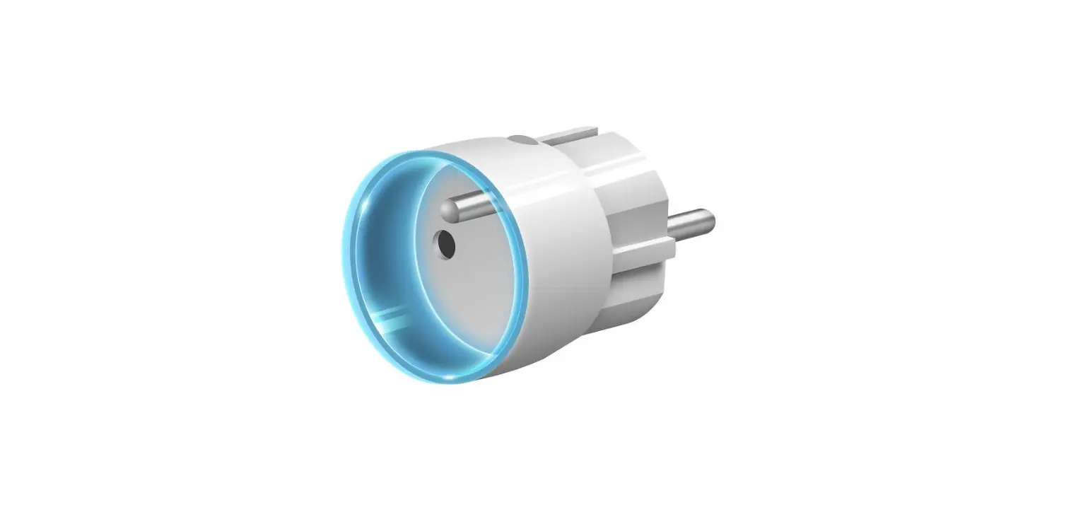
Product Description
Plug-Control is a universal, Z-Wave Plus compatible, remotely controlled outlet adapter. This device may be applied wherever you want to control electrical devices with up to 2500W load.Plug-Control is equipped with a power and energy metering function. It uses a LED ring to visualize the current load with colour changing illumination and operating mode. This is the smallest and most attractive device of this type available in the world.Plug-Control may be operated using the B-button located on its casing or via any Z-Wave compatible controller.
Prepare for Installation / Reset
Please read the user manual before installing the product.
In order to include (add) a Z-Wave device to a network it must be in factory default
state. Please make sure to reset the device into factory default. You can do this by
performing an Exclusion operation as described below in the manual. Every Z-Wave
controller is able to perform this operation however it is recommended to use the primary
controller of the previous network to make sure the very device is excluded properly
from this network.
Safety Warning for Mains Powered Devices
ATTENTION: only authorized technicians under consideration of the country-specific
installation guidelines/norms may do works with mains power. Prior to the assembly of
the product, the voltage network has to be switched off and ensured against re-switching.
Inclusion/Exclusion
On factory default the device does not belong to any Z-Wave network. The device needs
to be added to an existing wireless network to communicate with the devices of this network.
This process is called Inclusion.
Devices can also be removed from a network. This process is called Exclusion.
Both processes are initiated by the primary controller of the Z-Wave network. This
controller is turned into exclusion respective inclusion mode. Inclusion and Exclusion is
then performed doing a special manual action right on the device.
Quick trouble shooting
Here are a few hints for network installation if things dont work as expected.
- Make sure a device is in factory reset state before including. In doubt exclude before include.
- If inclusion still fails, check if both devices use the same frequency.
- Remove all dead devices from associations. Otherwise you will see severe delays.
- Never use sleeping battery devices without a central controller.
- Dont poll FLIRS devices.
- Make sure to have enough mains powered device to benefit from the meshing
Association – one device controls an other device
Z-Wave devices control other Z-Wave devices. The relationship between one device
controlling another device is called association. In order to control a different
device, the controlling device needs to maintain a list of devices that will receive
controlling commands. These lists are called association groups and they are always
related to certain events (e.g. button pressed, sensor triggers, …). In case
the event happens all devices stored in the respective association group will
receive the same wireless command wireless command, typically a ‘Basic Set’ Command.
Association Groups:
Group NumberMaximum NodesDescription
| 1 | 1 | u0022Lifelineu0022 reports the device status and allows for assigning single device only (main controller by default). |
| 2 | 10 | On/Off (Button) devices in this group will be switched on or off when relay status is changed using the B-button (uses Basic command class). |
| 3 | 10 | On/Off (Power) devices in this group will be switched on or off depending on the current load (uses Basic command class). |
Configuration Parameters
Z-Wave products are supposed to work out of the box after inclusion, however
certain configuration can adapt the function better to user needs or unlock further
enhanced features.
IMPORTANT: Controllers may only allow configuring
signed values. In order to set values in the range 128 … 255 the value sent in
the application shall be the desired value minus 256. For example: To set a
parameter to 200 it may be needed to set a value of 200 minus 256 = minus 56.
In case of a two byte value the same logic applies: Values greater than 32768 may
needed to be given as negative values too.
Parameter 1: Always On mode
In this mode Plug-Control will turn on connected device permanently and will stop reacting to attempts of turning it off (through Z-Wave network or pushing the B-button).Always On function turns Plug-Control into a power and energy meter. Connected device will not be turned off upon receiving an alarm frame from another Z-Wave device (parameter 31 will be ignored).In Always on mode, connected device may be turned off after exceeding the power defined in parameter 3 or in case of detecting current greater than 110% of rated current. In such cases, connected device can be turned on again by pushing the B-button or sending a control frame. By default, overload protection is inactive.
Size: 1 Byte, Default Value: 0
SettingDescription
| 0 | function inactive |
| 1 | function activated |
Parameter 10: High priority power report
This parameter determines the minimum percentage change in active power that will result in sending power report to the main controller with the highest priority in the Z-Wave network.By default, Plug-Control immediately sends the power report if the power load changes by 80%.
Size: 1 Byte, Default Value: 80
SettingDescription
| 1 – 99 | power change in percent |
| 100 | reports are disabled |
Parameter 11: Standard power report
This parameter determines the minimum percentage change in active power that will result in sending power report to the main controllerCompared to parameter 10, the maximum number of reports sent is reduced (parameter 12) to 5 in a specified time interval. In addition, the reports are not sent in mode, which may result in overloading the Z-Wave network.By default changes in power load may be reported up to 5 times per 30 seconds, when power load changes by 15%.
Size: 1 Byte, Default Value: 15
SettingDescription
| 1 – 99 | power change in percent |
| 100 | reports are disabled |
Parameter 12: Power reporting interval
This parameter defines the time interval of sending at most 5 standard power reports when the power changes by the value set in parameter 11. The higher the value of parameter 12, the fewer reports the device will send.By default Plug-Control sends up to 5 reports each 30 seconds, provided the power load changes by 15%.
Size: 2 Byte, Default Value: 30
SettingDescription
| 5 – 600 | in seconds |
Parameter 13: Energy reporting threshold
This parameter specifies the minimum change in energy consumption (in relation to the previously reported), that will result in sending a new report.
Size: 2 Byte, Default Value: 10
SettingDescription
| 0 | energy reports inactive |
| 1 – 500 | (0.01 – 5 kWh, step 0.01 kWh) – threshold |
Parameter 14: Power and energy periodic reports
This parameter defines time period between independent reports sent when changes in power load have not been recorded or if changes are insignificant. By default reports are sent every hour.
Size: 2 Byte, Default Value: 3600
SettingDescription
| 0 | periodic reports inactive |
| 5 – 32400 | in seconds |
Parameter 15: Measuring energy consumed by the Wall Plug itself
This parameter determines whether power metering should include the amount of power consumed by Plug-Control itself. Results are being added to the value of power consumed by controlled device.
Size: 1 Byte, Default Value: 0
SettingDescription
| 0 | function inactive |
| 1 | function activated |
Parameter 2: Remember device status before the power failure
This parameter determines how Plug-Control will react in the event of power supply failure (e.g. power outage or taking out from the electrical outlet).After the power supply is back on, Plug-Control can be restored to previous state or remain switched off.This parameter is ignored in Always On mode – the device automatically turns ON after plugging it into the socket.
Size: 1 Byte, Default Value: 0
SettingDescription
| 0 | device remains switched off |
| 1 | device restores the state from before the power failure |
Controlling devices with the B-Button. This parameter is inactive in Always On mode (parameter 1).Control as Plug-Control: switching Plug-Control onswitch the devices on (parameter 24) switching Plug-Control offswitch the devices off (parameter 24)Control opposite to Plug-Control: switching Plug-Control onswitch the devices off switching Plug-Control offswitch the devices on
Size: 1 Byte, Default Value: 0
SettingDescription
| 0 | control as the Wall Plug |
| 1 | control opposite to the Wall Plug |
Parameter 21: DOWN value – On/Off (Power) association group (3)
Lower power threshold, used in parameter 23. DOWN value cannot be higher than a value specified in parameter 22.
Size: 2 Byte, Default Value: 300
SettingDescription
| 0 – 24900 | 0.0 – 2490.0 W, step 0.1 W |
Parameter 22: UP value – On/Off (Power) association group (3)
Upper power threshold, used in parameter 23. UP value cannot be lower than a value specified in parameter 21.
Size: 2 Byte, Default Value: 500
SettingDescription
| 100 – 25000 | 10.0 – 2500.0 W, step 0.1 W |
Parameter 23: The response after exceeding defined power values
This parameter defines the way that 3rd association group devices are controlled. Depends on the actual measured power (as parameters 21 and 22 settings).
Size: 1 Byte, Default Value: 6
SettingDescription
| 1 | turn the associated devices ON, once the power drops below DOWN value (parameter 21) |
| 2 | turn the associated devices OFF, once the power drops below DOWN value (parameter 21) |
| 3 | turn the associated devices ON, once the power rises above UP value (parameter 22) |
| 4 | turn the associated devices OFF, once the power rises above UP value (parameter 22) |
| 5 | combination of 1 and 4. Turn the associated devices ON, once the power drops below DOWN value (parameter 21). Turn the associated devices OFF, once the power rises above UP value (parameter 22). |
| 6 | combination of 2 and 3. Turn the associated devices OFF, once the power drops below DOWN value (parameter 21). Turn the associated devices ON, once the power rises above UP value (parameter 22). |
Parameter 24: SWITCH ON value – On/Off association groups
The value of BASIC SET command frame sent to the devices associated in On/Off association groups (2, 3).On/Off (Button) association group – in accordance with parameter 20.On/Off (Power) association group – in accordance with parameter 23.
Size: 2 Byte, Default Value: 255
SettingDescription
| 0 – 99 | sent value |
| 255 | sent value |
Parameter 3: Overload safety switch
This function allows to turn off the controlled device in case of exceeding the defined power. Controlled device will be turned off even if Always On function is active (parameter 1).Controlled device can be turned back on via B-button or sending a control frame. By default this function is inactive.CAUTION! – The device has a protection that will turn the load off in the case of detecting current greater than 110% of rated current (>12A). It is a safety function and it cannot be turned off. After its activation the load can be turned on back again by pressing the B-button or sending a control frame. This function is independent of overload safety switch set in the parameter no. 3.
Size: 2 Byte, Default Value: 0
SettingDescription
| 0 | function inactive |
| 10 – 30000 | (1.0 – 3000.0 W, step 0.1 W) – power threshold |
Parameter 30: Active alarms
Define Z-Wave network alarms to which Plug-Control will respond.
Size: 1 Byte, Default Value: 63
SettingDescription
| 1 | general alarm |
| 0 | no alarm |
| 2 | smoke alarm |
| 4 | CO alarm |
| 8 | CO2 alarm |
| 16 | high temperature alarm |
| 32 | flood alarm |
| 63 | all alarms |
Parameter 31: Response to alarm frames
This parameter defines how Plug-Control will respond to alarms (devices status change).In case of values 1 or 2 Plug-Control is operating normally and LED ring signals an alarm through time defined in parameter 32 or until the alarm is cancelled.In case of values 5 to 50 Plug-Control does not report status change, power changes, ignores BASIC SET command frames. After time defined in parameter 32 or after the alarm cancellation, connected device is set to the previous state.
Size: 1 Byte, Default Value: 0
SettingDescription
| 0 | no reaction |
| 1 | turn connected device on |
| 2 | turn connected device off |
| 5 – 50 | (0.5 – 5.0 s, step 0.1 s) – cyclically change device state with set period |
Parameter 32: Alarm state duration
This parameter specifies the duration of alarm state. If a device sending an alarm frame through the Z-Wave network sets alarm duration as well, this settings are ignored.
Size: 2 Byte, Default Value: 600
SettingDescription
| 1 – 32400 | in seconds |
Parameter 40: Power load for violet colour
This parameter determines maximum active power value, which when exceeded, causes the LED ring flash violet. Function is active only when parameter 41 is set to 1 or 2.
Size: 2 Byte, Default Value: 25000
SettingDescription
| 1000 – 30000 | 100.0 – 3000.0 W, step 0.1 W |
Parameter 41: LED ring colour when controlled device is on
When set to 1 or 2, LED ring colour will change depending on active power and parameter 40. Other colours are set permanently and do not depend on power consumption.
Size: 1 Byte, Default Value: 1
SettingDescription
| 0 | illumination turned off completely |
| 1 | colour changes continuously depending on active power |
| 2 | colour changes in steps depending on active power |
| 3 | white |
| 4 | red |
| 5 | green |
| 6 | blue |
| 7 | yellow |
| 8 | cyan |
| 9 | magenta |
Parameter 42: LED ring colour when controlled device is off
This parameter defines the illumination colour after turning off.
Size: 1 Byte, Default Value: 0
SettingDescription
| 0 | illumination turned off completely |
| 1 | LED ring is illuminated with a colour corresponding to the last measured power, before the controlled device was turned off |
| 3 | white |
| 4 | red |
| 5 | green |
| 6 | blue |
| 7 | yellow |
| 8 | cyan |
| 9 | magenta |
Parameter 43: LED ring colour at the Z-Wave network alarm detection
This parameter defines the illumination colour in case of Z-Wave alarm.
Size: 1 Byte, Default Value: 2
SettingDescription
| 0 | illumination turned off completely |
| 1 | no change in colour. LED ring colour is determined by settings of parameters 41 or 42 |
| 2 | LED ring flashes red/blue/white |
| 3 | white |
| 4 | red |
| 5 | green |
| 6 | blue |
| 7 | yellow |
| 8 | cyan |
| 9 | magenta |
Parameter 50: Associations in Z-Wave network security mode
This parameter defines how commands are sent in specified association groups: as secure or non-secure. Parameter is active only in Z-Wave network security mode. This parameter does not apply to 1st Lifeline group.
Size: 1 Byte, Default Value: 3
SettingDescription
| 0 | none of the groups sent as secure |
| 1 | 2nd group sent as secure |
| 2 | 3rd group sent as secure |
| 3 | 2nd and 3rd group sent as secure |
Technical Data
| Hardware Platform | ZM5202 |
| Device Type | On/Off Power Switch |
| Network Operation | Always On Slave |
| Firmware Version | HW: 2 FW: 3.02:03.02 |
| Z-Wave Version | 6.51.07 |
| Certification ID | ZC10-22047083 |
| Z-Wave Product Id | 0x010F.0x0602.0x1003 |
| Color | White |
| Frequency | XXfrequency |
| Maximum transmission power | XXantenna |
Supported Command Classes
- Application Status
- Association Grp Info
- Association V2
- Basic
- Switch Binary
- Configuration
- Crc 16 Encap
- Device Reset Locally
- Firmware Update Md V3
- Manufacturer Specific V2
- Meter V2
- Multi Channel Association V3
- Notification V5
- Powerlevel
- Security
- Sensor Multilevel V5
- Version V2
- Zwaveplus Info V2
Controlled Command Classes
- Basic
- Multi Channel V4
Explanation of Z-Wave specific terms
- Controller — is a Z-Wave device with capabilities to manage the network.
Controllers are typically Gateways,Remote Controls or battery operated wall controllers. - Slave — is a Z-Wave device without capabilities to manage the network.
Slaves can be sensors, actuators and even remote controls. - Primary Controller — is the central organizer of the network. It must be
a controller. There can be only one primary controller in a Z-Wave network. - Inclusion — is the process of adding new Z-Wave devices into a network.
- Exclusion — is the process of removing Z-Wave devices from the network.
- Association — is a control relationship between a controlling device and
a controlled device. - Wakeup Notification — is a special wireless message issued by a Z-Wave
device to announces that is able to communicate. - Node Information Frame — is a special wireless message issued by a
Z-Wave device to announce its capabilities and functions.


 Tzwp-101 Manual")


