
HEAVY DUTY CMS-120 Coolant
INTRODUCTION
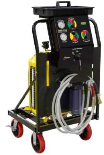
Congratulations on the purchase of your CMS-120 Coolant Maintenance System.
The Flo-Dynamics CMS-120 Coolant Maintenance System, with a single
20-gallon tank allows a technician to quickly drain and refill a large capacity cooling system in minutes.
Using push/pull technology, the CMS-120 simultaneously uses pressure and vacuum, speeding up both the draining and filling processes. Refilling, without the need to spend hours bleeding air from a cooling system, is easy using push/pull technology and a vehicle’s Flush-Face Quick Connect Coupler cooling system adapter.
Without the need to use a drain pan, you can safely, quickly, and completely drain a 14-gallon cooling system in approximately 10 minutes, and refill without air pockets in 13 minutes.
The CMS-120 will save repair time costs along with creating a safer shop environment by preventing coolant spills.
Please take time to read through this manual to familiarize yourself with the machine before performing your first coolant drain or exchange.
CUSTOMER SERVICE CONTACT INFORMATION
For product information and tech support please call: 800-303-5874 or visit: www.flodynamics.com
Flo-Dynamics, Inc. • 3300 Reedy Drive • Elkhart, IN 46514 • 800-303-5874 • flodynamics.com
IMPORTANT SAFETY NOTICE
For your safety, read this manual thoroughly before operating this machine. This machine is intended for use by properly trained, skilled professional automotive technicians. The safety messages presented below and throughout this user’s manual are reminders to the operator to exercise care when using this unit. Before using this machine, always refer to and follow the safety messages and applicable service procedures provided by the manufacturer of the vehicle being serviced.
Read All Safety Instructions
Read, understand, and follow all safety messages and instructions in this manual. Safety messages in this section of the manual contain a signal word with a three-part message and, in some instances, an icon.
Signal Words
The signal word indicates the level of the hazard in a situation:
DANGER:
Indicates an imminently hazardous situation which, if not avoided, will result in death or serious injury to the operator or to bystanders.
WARNING:
Indicates a potentially hazardous situation which, if not avoided, could result in death or serious injury to the operator or to bystanders.
CAUTION:
Indicates a potentially hazardous situation which, if not avoided, may result in moderate or minor injury to the operator or to bystanders.
IMPORTANT:
Indicates a situation which, if not avoided, may result in damage to the machine, or the vehicle being serviced.
Safety Messages
Safety messages in this section contain three different type styles:
- Normal type states the hazard.
- Bold type states how to avoid the hazard.
- Italic type states the possible consequences of not avoiding the hazard.
Safety Symbols
A safety symbol, when present, gives a graphical description of the potential hazard, and how to avoid the hazard: 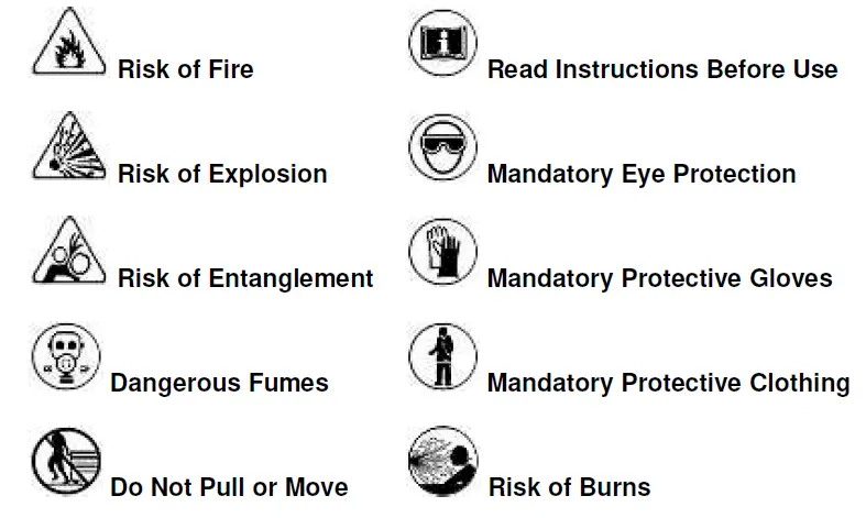
IMPORTANT SAFETY INSTRUCTIONS
DANGER:
Engine exhaust contains toxic gases.
- Vent vehicle’s exhaust away from work area.
- Do not breathe exhaust. Exhaust gases will cause injury or death.
WARNING:
Improper use and operation.
- Read, understand and follow all safety messages and operational procedures in this manual before operating this machine.
- This equipment should be operated only by qualified personnel.
- Use this equipment only as described in this manual.
- Improper use and operation of this product can result in injury.
WARNING:
Engine systems can malfunction expelling fuel, oil vapors, hot steam, hot toxic exhaust gases and other flying particles.
- Wear safety goggles and protective clothing, user and bystander. Everyday eyeglasses only have impact resistant lenses; they are NOT safety glasses.
- Do not position head directly over or in front of carburetor or throttle body. Engine backfire can occur when air cleaner is out of normal position.
- Make sure gauge reads zero before connecting or disconnecting hose connections to adapters.
- Make sure cooling system pressure has been relieved before connecting or disconnecting hose connections and adapters.
- Keep a dry chemical (Class B) fire extinguisher rated for gasoline, chemical & electric fires in the work area.
Fire, explosion, or flying particles may cause serious injury.
WARNING:
Risk of expelling pressurized fluids.
- Wear safety goggles and protective clothing, user, and bystander.
- Engine systems can malfunction, expelling fuel, oil vapors, hot steam, hot toxic exhaust gases and other debris.
- Always unplug the machine from its power source when not in use.
- Keep the service hoses away from hot or moving engine parts. Hoses can split or burst causing fluid to be expelled.
- Avoid contact with engine coolant.
- Treatment methods are as follows:
- Eyes: Flush eyes with plenty of water.
- Skin: Wash with soap and water.
- Inhalation: Move to uncontaminated area.
- Ingestion: If large amount, get medical attention.
- If any irritation persists, get medical attention.
- Dispose of used fluid according to environmental laws and regulations.
Fuel, oil vapors, hot steam, hot toxic exhaust gases, pressurized fluid, and other debris can cause serious injury.
WARNING:
Risk of unexpected vehicle movement.
- Block drive wheels before starting vehicle’s engine to begin an exchange.
- Unless instructed otherwise, set parking brake and put gear selector in park.
- Do not leave a running vehicle unattended.
- If vehicle has an automatic parking brake release, disconnect release mechanism for testing and reconnect when testing is completed.
A moving vehicle can cause injury.
WARNING:
Risk of entanglement. Engine has moving parts.
- Do not place tools on fenders or other places in engine compartment.
- Keep yourself, clothing, battery cables and service hoses clear of moving parts such as fan blades, belts, pulleys, hood and doors.
- Barriers are recommended to help identify danger zones in test area.
- Prevent personnel from walking through immediate test area.
Contact with moving parts can cause injury.
WARNING:
Risk of fire or explosion.
- Do not operate in the vicinity of open containers of flammable liquids such as gasoline.
- Keep hoses and jumper cables away from heat sources and sharp edges.
- Do not operate equipment with damaged cords or hoses until they have been examined by a qualified serviceman.
Fire or explosion can cause injury.
WARNING:
Risk of fire or explosion. Gases produced by a battery are highly explosive.
- Wear safety goggles and protective clothing, user and bystander.
- Do not smoke, place metal tools on battery or allow a spark or flame in vicinity of battery. Battery explosion can cause injury.
WARNING:
Risk of burns.
- Wear gloves when handling hot engine components.
- Do not remove radiator cap unless engine is cold.
- Pressurized engine coolant may be hot.
- Do not touch hot exhaust systems, manifolds, engines, radiators, etc. Hot fluid and engine parts may cause injury.
WARNING:
Battery acid is a highly corrosive sulfuric acid.
- Wear safety goggles and protective gloves, user and bystander.
- Have plenty of fresh water and soap nearby. If battery acid contacts skin, clothing, or eyes, flush exposed area with soap and water for 10 minutes.
- Do not touch eyes while working near battery.
Battery acid can burn eyes and skin.
WARNING:
Risk of burns.
- Wear gloves when working near hot engine components.
- Do not touch hot exhaust systems, manifolds, engines, radiators, etc.
- The fluid coming from the vehicle along with some of the machine’s components that the fluid comes into direct contact with (i.e. hoses and fittings) may reach temperatures uncomfortable to the touch. Exercise caution in avoiding contact with these items.
Hot components can cause injury or discomfort.
CAUTION:
Risk of injury.
- This equipment should be operated by qualified personnel only.
- Use this equipment only as described in this manual.
- Always disconnect the machine from air source when not in use.
- Loop the pressure hose loosely in its proper location when machine is not in use.
- Do not operate equipment with a damaged hose, or if the equipment has been dropped or damaged, until it has been examined by a qualified service representative.
- Care should be taken to arrange the service hoses so that they will not be tripped over or pulled.
- Never pull on the service hoses to transport the machine. Damage may occur to these components, or machine may tip over.
- Keep area of operation clear of unnecessary tools and equipment. Utilize recessed tool storage areas on the top of the machine.
- Never leave the machine running unattended.
- This machine is not designed for any other purpose than the servicing of automotive cooling systems.
Operation of this machine by anyone other than qualified personnel may result in injury.
CAUTION:
Misdiagnosis may lead to incorrect or improper repair and/or adjustment.
- Do not rely on erratic, questionable, or obviously erroneous test information or results. If test information or results are erratic, questionable, or obviously erroneous, make sure that all connections and data entry information are correct and that the test procedure was performed correctly. If test information or results are still suspicious, do not use them for diagnosis.
- Improper repair and/or adjustment may cause vehicle or equipment damage or unsafe operation.
IMPORTANT:
Risk of equipment damage.
- Servicing, transporting, or storing this machine in an attitude other than the normal operating position can result in fluid spillage and/or component damage.
- Never pull on the service hoses to transport the unit. Damage may occur to these components, or machine may tip over. Always use the handle to move.
- Periodically clean the machine by wiping down with a clean, soft, dry cloth. Improper operation of equipment may result in damage to machine or components.
MACHINE SPECIFICATIONS
- Dimensions: 56” H x 28” W x 24” D
- Weight: 166 lbs.
- Fluid Capacity: 20 gallons
- Power: 115 psi shop air
- Hose Length: 13’ outside of machine
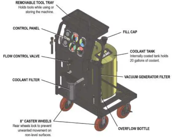
FEATURES
- Single 20-gallon tank with fluid level sight tube
- Easy mobility cart with heavy duty 8” casters
- Easy to use — no 120V or 12V power required
- Operates on shop air
- Push/pull technology enables:
- Quickly draining a 14-gallon cooling system in 10 minutes
- Filling a 14-gallon cooling system w/o air pockets in 13 minutes
- Filters and cleans coolant when draining a system
- Easy to see coolant level in tank
- Internally coated tank prevents rust contamination
- Removable tool tray
- 13’ polyurethane service hoses
- Flush-face quick connect couplers available
- Optional adapters available
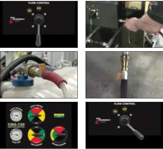
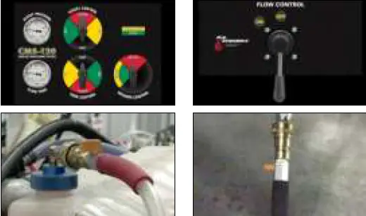
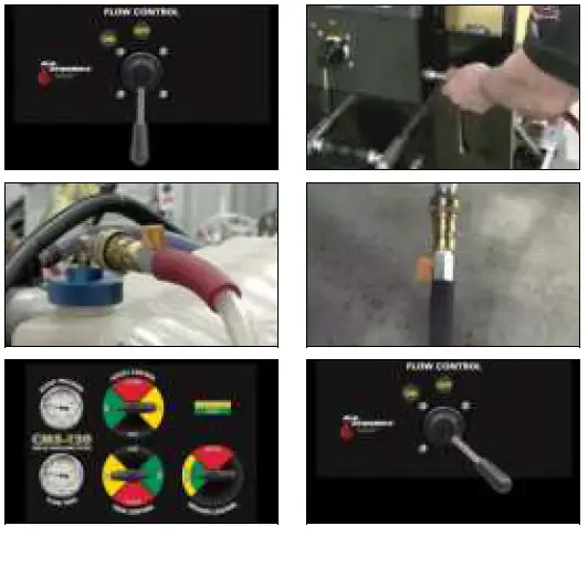
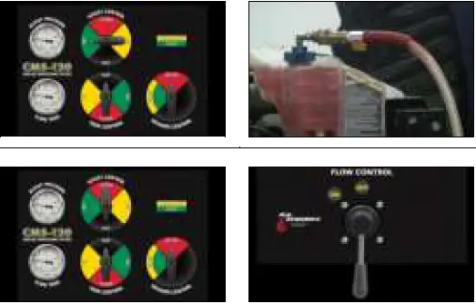
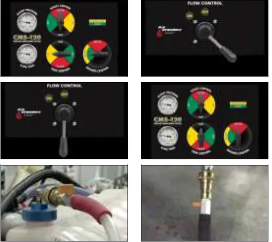
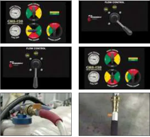
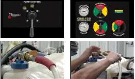
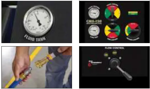
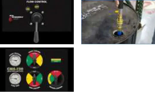
MACHINE OVERVIEW
OPERATING INSTRUCTIONS
SAFETY RECOMMENDATIONS
- Use extreme safety measures when working around a running engine, pressurized storage vessels, and automotive chemicals.
- Always block the vehicle’s drive wheels.
- Ventilate the vehicle’s exhaust if engine will be started.
- Always wear safety glasses.
- Protective gloves are recommended.
PREPARATION
- Inspect the engine and the visible coolant system components for any signs of damage or unusual wear.
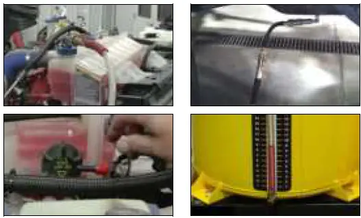
- Note the coolant level before beginning the service. If low, see “COOLING SYSTEM PRESSURE / LEAK CHECK” procedure to verify the system’s condition.
- Depending on the desired service, make appropriate connections (lowest and highest point) on the vehicle’s coolant system.
- Plug any open ports venting to the atmosphere (i.e. overflow hose or a system vent cap).
- To prevent running out of coolant and ingesting air, ensure coolant tank level is showing at least 3 gallons on the sight tube.

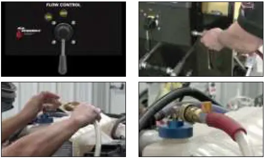
PERFORM COOLANT DRAIN and CLEAN OPERATION
DRAIN COOLANT FROM VEHICLE INTO COOLANT TANK
- Obtain a coolant sample if needed.
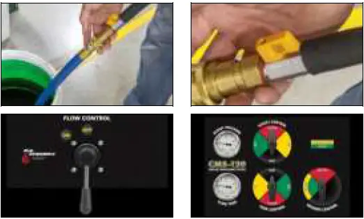
- Move the Flow Control to “OFF” and connect shop air.
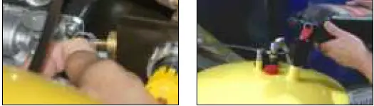
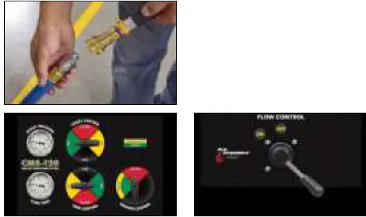
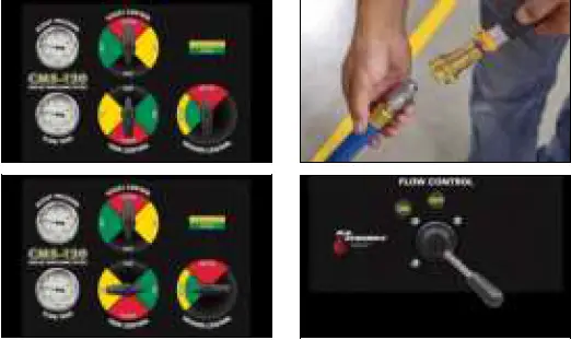
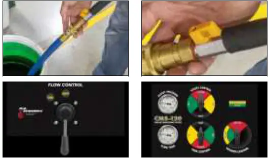
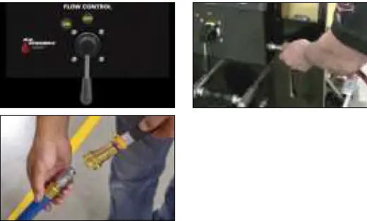
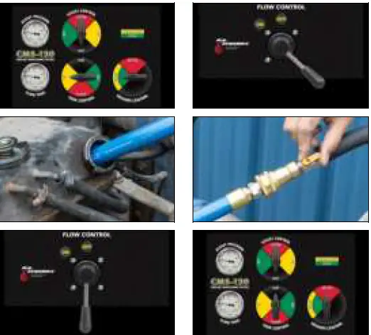
- Connect the red service hose to highest point, the black service hose to the lowest point, and open the ball valves.
- Turn all control panel valves to the YELLOW position.
- Move the Flow Control to “ON”.
- The system will begin to drain.

- When air is seen in the black hose, turn Tank Control and Assist Control to VENT and Vacuum Control to OFF.
- When air pockets/coolant stop moving in the service hoses, move the Flow Control to “OFF”.
- Close the ball valves and remove the service hoses.

PERFORM COOLANT FILL OPERATION
RETURN COOLANT TO VEHICLE AFTER SERVICING
- Move the Flow Control to “OFF” and connect shop air.
- Connect the red service hose to highest point, the black service hose to the lowest point, and open the ball valves.
- Turn all control panel dials to the GREEN position. Move the Flow Control to “ON”.
- The system will begin to fill.

- When the coolant level is at the “cold” level of the expansion tank or seen in the red hose, the system is full.
- Turn Tank Control to VENT and Vacuum Control to OFF. The coolant level will adjust.

- When the coolant returns to the “cold” level on the expansion tank, turn Assist Control to VENT.
- When the cooling system stabilizes and both gauges show zero, move the Flow Control to “OFF”.
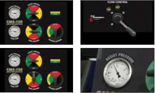
TO ADJUST COOLANT LEVEL IF IT’S TOO HIGH
- Turn Tank Control and Vacuum Control to YELLOW and Assist Control to VENT.
- Move the Flow Control to “ON” until the desired coolant level is reached.
- Move the Flow Control to “OFF” and turn Vacuum Control and Assist Control to VENT.
- Close the ball valves and remove the service hoses.
- NOTE: If cooling system overfills and coolant is seen in the top service hose going into the vacuum generator overflow filter, stop flow immediately by moving Flow Control to “OFF”. See “VACUUM GENERATOR OVERFLOW FILTER REPLACEMENT” procedure to empty overflow filter assembly.

TOP-OFF PROCEDURE / COOLANT LEVEL TOO LOW
- NOTE: The following procedure is performed with the red and black service hoses still connected from filling the cooling system in the above procedure.
- Turn Tank Control to Green, Assist Control to VENT and Vacuum Control to OFF.
- Move the Flow Control to “ON”.
- When coolant is at the correct level, move the Flow Control to “OFF”, Tank Control to VENT.
- When the cooling system stabilizes and both gauges show zero, close the ball valves and remove the service hoses.

ADDITIONAL FUNCTIONS
COOLING SYSTEM PRESSURE / LEAK CHECK
- Move the Flow Control to “OFF” and connect shop air to the machine.
- Close the ball valve on the red service hose. Connect the red service hose to the top of the radiator using the appropriate adapter and open the ball valve.

- Turn Tank Control and Assist Control to YELLOW position.
- Move the Flow Control to “ON”.
- The system will pressurize to 10-15psi.
- Turn Tank Control to RED and observe the Fluid Tank pressure gauge. If there is a loss of pressure, then there is a leak in the cooling system.

- When enough time has elapsed to properly perform a pressure check, move the Flow Control to “OFF” and Tank Control and Asist Control to VENT.
- Close the ball valve on the red service hose and remove the red service hose. Remove the adapter from the radiator and replace the cap.

FILL TANK – METHOD 1 POUR IN
- Ensure there is no pressure or vacuum in the new coolant tank by pulling up on the relief valve ring on top of the tank.
- Remove the fill cap. Add the required amount of new coolant and replace the fill cap.

FILL TANK – METHOD 2 VACUUM MODE
- If the Fluid Tank gauge indicates pressure or a vacuum, turn Tank Control to VENT to equalize tank to zero.
- Close the ball valve on the BLACK service hose and connect the open-end adapter.
- Turn Tank Control and Vacuum Control to Yellow.
- Move the Flow Control to “ON”.
- Place the open-end adapter into a new coolant container and open the ball valve on BLACK hose.

- When the coolant level in coolant tank reaches the desired level, move the Flow Control to “OFF” and close the ball valve on the BLACK service hose.
- Move Vacuum Control to OFF and move Tank Control to VENT.

DRAINING THE TANK
- Close the ball valve on the black service hose and connect the open-end adapter.
- Turn Tank Control and Assist Control to GREEN.
- Move the Flow Control to “ON”

- Place the open-end adapter into an approved coolant waste container and open the ball valve. Drain until the tank is empty.
- Move the Flow Control to “OFF” and Tank Control and Assist Control to VENT to release pressure in the tank.
- Dispose of used coolant in accordance with local and state requirements.

EMPTY OVERFLOW BOTTLE
- Release the Velcro strap and remove the overflow bottle.
- Empty contents into an approved coolant waste container.
- Rinse out and replace using Velcro strap.


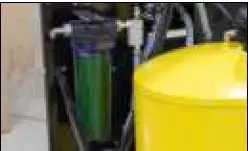
VACUUM GENERATOR OVERFLOW FILTER REPLACEMENT
- The vacuum generator overflow filter should be emptied when it is more than 1/3 full.
- Remove the reservoir by turning it counterclockwise.
- Empty the reservoir contents into an approved coolant waste container, rinse out the reservoir, and replace the filter if necessary.
- After ensuring the rubber O-ring is in place, reinstall the reservoir by turning clockwise until seated.

COOLANT FILTER REPLACEMENT
- If pressure or a vacuum is shown on either tank gauge, depressurize the tanks by turning Tank Control and Assist Control to VENT.
- Close the ball valve on the black service hose and connect the open-end adapter.
- Turn Tank Control and Vacuum Control to GREEN and move the Flow Control to “ON”.

- Place the open-end adapter into an approved coolant waste container and open the ball valve.
- NOTE: The reservoir will not completely empty and will only empty past the threads, so the reservoir may be removed without spillage.
- Once at this level, move the Flow Control to “OFF”, turn Tank Control to VENT, and Vacuum Control to OFF.

- Remove the reservoir by turning it counterclockwise. Empty the reservoir contents into an approved coolant waste container, rinse out the reservoir, and replace the filter if necessary.
- After ensuring the rubber O-ring is in place, reinstall the reservoir by turning clockwise until seated.


REMOVE COOLANT FROM A VEHICLE’S EXPANSION / DE-GAS BOTTLE
- Move the Flow Control to “OFF” and connect shop air to the machine.
- Close the ball valve on the black service hose and connect the open-end adapter.

- Turn Tank Control and Vacuum Control to YELLOW and Assist Control to VENT.
- Move the Flow Control to “ON” until the desired coolant level is reached.
- Move the Flow Control to “OFF” and turn Tank Control and Vacuum Control to VENT.
- Close the ball valves and remove the service hoses.

MAINTENANCE
To keep your machine working properly:
- Keep debris out of fluid tanks.
- Inspect and if needed clean filter before each use.
- Inspect air catch container and clean before each use.
- Avoid spilling fluid on control panel.
REPLACEMENT PARTS
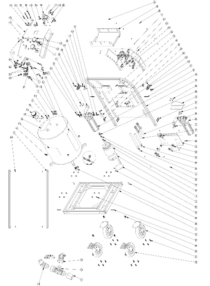
| ITEM # | PART NO. | DESCRIPTION | QTY. |
| 10 | R942131 | JACKNUT 10-24 | 4 |
| 11 | 941390 | NUT 3,8-16 STAR LOCK | 16 |
| 12 | 941271 | BOLT 3/8-16 x 1 BUTTON SOCKET | 16 |
| 13 | 40201170 | SCREW NO 8, 3/4″ LENGTH | 8 |
| 14 | R942142 | HOSE CLAMP 3/8 SCREW TYPE | 16 |
| 15 | 40200171 | NUT-HEX 10-32 TOOTHED WASHER | 18 |
| 16 | 40200821 | 10-32 X 3/8 BUTTON HEAD SCREW STAINLESS | 22 |
| 17 | 40201288 | SCREW – HEX SS-316, FT 1/4-20 X 2- 1/4 | 12 |
| 18 | 40201289 | NUT – SS-316 NYLON, 1/4-20 | 12 |
| 19 | 40201025 | MALE ELBOW 5/16″ TUBE 1/4NPT | 8 |
| 20 | 40201124 | ELBOW, 5/16″ TUBE OD x 3/8″ NPT MALE | 7 |
| 21 | 40201129 | UNION TEE 5/16 TUBE | 6 |
| 22 | 40201152 | HEX SCREW 5/8-18 X 1″ | 4 |
| 23 | 40201154 | HEX NUT 5/8-18, 5 | 4 |
| 24 | 40300398 | ASSEMBLY-COMMFLUSH CART MODULE | 1 |
| 25 | 40300370 | PUSH CART HANDLE ASSEMBLY | 1 |
| 26 | 40201145 | STEEL TANK 20 GAL | 1 |
| 27 | 40300423 | FRONT COWL, HD CMS | 1 |
| 28 | 40300373 | CART FILTER PANEL | 1 |
| 29 | 40300410 | ADAPTER TRAY BRACKET | 1 |
| 30 | 40201057 | CASTER 8IN DIA WITH BRAKE | 2 |
| 31 | 40201056 | CASTER 8IN DIA NO BRAKE | 2 |
| 32 | 40201186 | Tool Tray | 1 |
| 33 | 40300361 | GUSSET BAR | 2 |
| 34 | 40300427 | REVERSER STOP | 1 |
| 35 | 40300396 | FILTER HOUSING MNT BRKT | 1 |
| 36 | 40300422 | HOSE RACK HD CMS | 1 |
| 37 | 40201099 | ELBOW 90 DEG. 1/2 BARB HOSE ID X 3/4 NPT MALE | 1 |
| 38 | 40201156 | CAP – CMS-40 | 1 |
| 39 | 40201298 | ELBOW 45 DEG | 1 |
| 40 | 40201299 | TEE FITTING | 1 |
| 41 | P941437 | BOTTLE HOLD PLATE-BLK VACFILL3 | 1 |
| 42 | 941424 | BOTTLE-PLASTIC OVRFLO | 1 |
| 43 | 941425 | STRAP-VELCRO BOTTLE HOLDER | 1 |
| 44 | 40201075 | COOLANT TANK CAP W/ SEAL ONLY | 1 |
| 45 | 40200356 | 5/16 TUBE X 1/8 NPT ELBOW W169PLP3 5-2 | 1 |
| 46 | 40201040 | NEW FLUID FUNNEL FITTING | 1 |
| 47 | 40201159 | BRASS BARB | 6 |
| 48 | 940114 | 90 JIC ELBOW | 4 |
| ITEM # | PART NO. | DESCRIPTION | QTY. |
| 49 | 40201140 | 10″ FILTER HOUSING CMS | 1 |
| 50 | 40201161 | FILTER CHECK VALVE ASSEMBLY | 1 |
| 51 | 40201180 | FILTER ELEMENT – CMS-40 | 2 |
| 52 | 40201182 | BUSHING ADAPTER, 3/4″ MNPT x 1/4″ FNPT | 2 |
| 53 | 941328 | CONNECTOR 1,4NPT 1,4NPT 216P-4 | 1 |
| 54 | 91078A255 | HEX NUT THIN 1″-14 ZINC | 2 |
| 55 | 40201258 | ELBOW ADAPTER 1/2″ BARB X 1/2 NPT FEMALE PVDF | 2 |
| 56 | 941109 | ELBOW 1/2 NPT X 1/2 JIC | 1 |
| 57 | 947001 | 4 WAY REGULATOR-PSICOOL | 2 |
| 58 | 40200875 | VACUUM GENERATOR CV15H | 1 |
| 59 | 40200463 | REVERSER – G TEC 7AR | 1 |
| 60 | 941335 | AIR NIPPLE 1/4NPT H2C | 1 |
| 61 | 40200339 | 1/4 BRASS BULKHEAD FTTG | 1 |
| 62 | 40201147 | HIGH-NOISE REDUCING MUFFLER | 1 |
| 63 | 945011 | FITTING-1/4FPT X 1/4FPT STRAIT | 3 |
| 64 | 40200565 | HOSE BARB 1/2 – G TEC ADAPTERS | 2 |
| 65 | 40201192 | PRESSURE RELIEF VALVE 1/8 NPT – 30 PSI | 1 |
| 66 | 40201263 | PLASTIC TEE CONNECTOR 1/2 HOSE BARB | 1 |
| 67 | 944009 | BULKHEAD ELBOW W,NUT 1/2 JIC | 1 |
| 68 | 40201201 | 90 ELBOW – ½ MALE JIC x ½ FEM JIC SWIVEL | 1 |
| 69 | 40200534 | ELBOW 6-6 – G TEC | 2 |
| 70 | 941277 | 4WAY VALVE ANDERSON B 200CN- 12 | 3 |
| 71 | 941438 | 2.5 PANEL GAUGE AND U-CLAMP | 2 |
| 72 | 941451 | PLUG-3,8MPT | 2 |
| 73 | 40201128 | STUD 5/16 TUBE 3/8NPT | 2 |
| 74 | 40201127 | STUD N2 – 5/16 TUBE X 1/4 NPT | 2 |
| 75 | 40201296 | TUBING CLEAR BRAIDED PVC – 1/2 ID X 3/4 OD | 1 |
| 76 | 40200577 | 3/8 ID BLACK HOSE | 1 |
| 77 | 40201179 | BLACK POLY TUBING 5/16 OD | 1 |
| 78 | 40201122 | RED SERVICE HOSE | 1 |
| 79 | 40201123 | BLACK SERVICE HOSE | 1 |
| 80 | 40201189 | CMS-240 ADAPTER | 1 |
| 81 | 940144 | HOSE,ATF2000,ADAPTER 4 | 1 |
| 82 | 40201176 | USED FLUID TANK ID LABEL – CMS- 240 | 1 |
| 83 | 40201193 | OPS MANUAL CMS-120 | 1 |
| 84 | 40201194 | JOB AID SHEET CMS-120 | 1 |
| 85 | 40201301 | OVERLAY – UPPER CONTROL PANEL – CMS-120 | 1 |
| 86 | 40201303 | PRODUCT LABEL – CMS-120 | 1 |
| 87 | 40201302 | OVERLAY – MEASURING STRIP – CMS- 120 | 1 |
LIMITED ONE (1) YEAR WARRANTY
Flo-Dynamics CMS-120
Flo-Dynamics warrants only to the original Purchaser that under normal use, care and service, the Equipment (except as otherwise provided herein) shall be free from defects in material and workmanship for one year from the date of original invoice. External hoses, remote control modules, adapters, and all other attachments, supplies and consumables (except as otherwise provided herein) are warranted for 90 calendar days from the date of original invoice. Filter elements are not warranted. Printed circuit boards purchased from, but not installed by Seller are not warranted.
SELLER’S OBLIGATIONS UNDER THIS WARRANTY ARE LIMITED SOLELY TO THE REPAIR OR, AT SELLER’S OPTION, REPLACEMENT OF EQUIPMENT OR PARTS WHICH TO SELLER’S SATISFACTION ARE DETERMINED TO BE DEFECTIVE AND WHICH ARE NECESSARY, IN SELLER’S JUDGEMENT, TO RETURN THE EQUIPMENT TO GOOD OPERATING CONDITION. NO OTHER WARRANTIES EXPRESS OR IMPLIED OR STATUTORY, INCLUDING WITHOUT LIMITATION ANY IMPLIED WARRANTY OF MERCHANTABILITY OR FITNESS FOR A PARTICULAR PURPOSE, SHALL APPLY AND ALL SUCH WARRANTIES ARE HEREBY EXPRESSLY DISCLAIMED.
This warranty does not cover (and separate charges for parts, labor and related expenses shall apply to) any damage to, malfunctioning, inoperability or improper operation of the Equipment caused by, resulting from or attributable to (A) abuse, misuse or tampering; (B) alteration, modification or adjustment of the Equipment by anyone other than Seller’s authorized representatives; (D) improper or negligent use, application, operation, care, cleaning, storage or handling; (E) fire, water, wind, lightning or other natural causes; (F) adverse environmental conditions, including, without limitation, excessive heat, moisture, corrosive elements, or dust or other air contaminants, radio frequency interference, electric power failure, power line voltages beyond those specified for the equipment, unusual physical, electrical or electromagnetic stress, and/or any other condition outside of Seller’s environmental specifications; (G) use of the Equipment in combination or connection with other equipment, attachments, supplies or consumables not manufactured or supplied by Seller; or (H) failure to comply with any applicable federal, state or local regulation.
Repairs or replacements qualifying under this Warranty will be performed on regular business days during Seller’s normal working hours within a reasonable time following Purchaser’s request. All requests for Warranty service must be made during the stated Warranty period. This warranty is non-transferable.
Flo-Dynamics, Inc. • 3300 Reedy Drive • Elkhart, IN 46514 • 800-303-5874 • flodynamics.com


