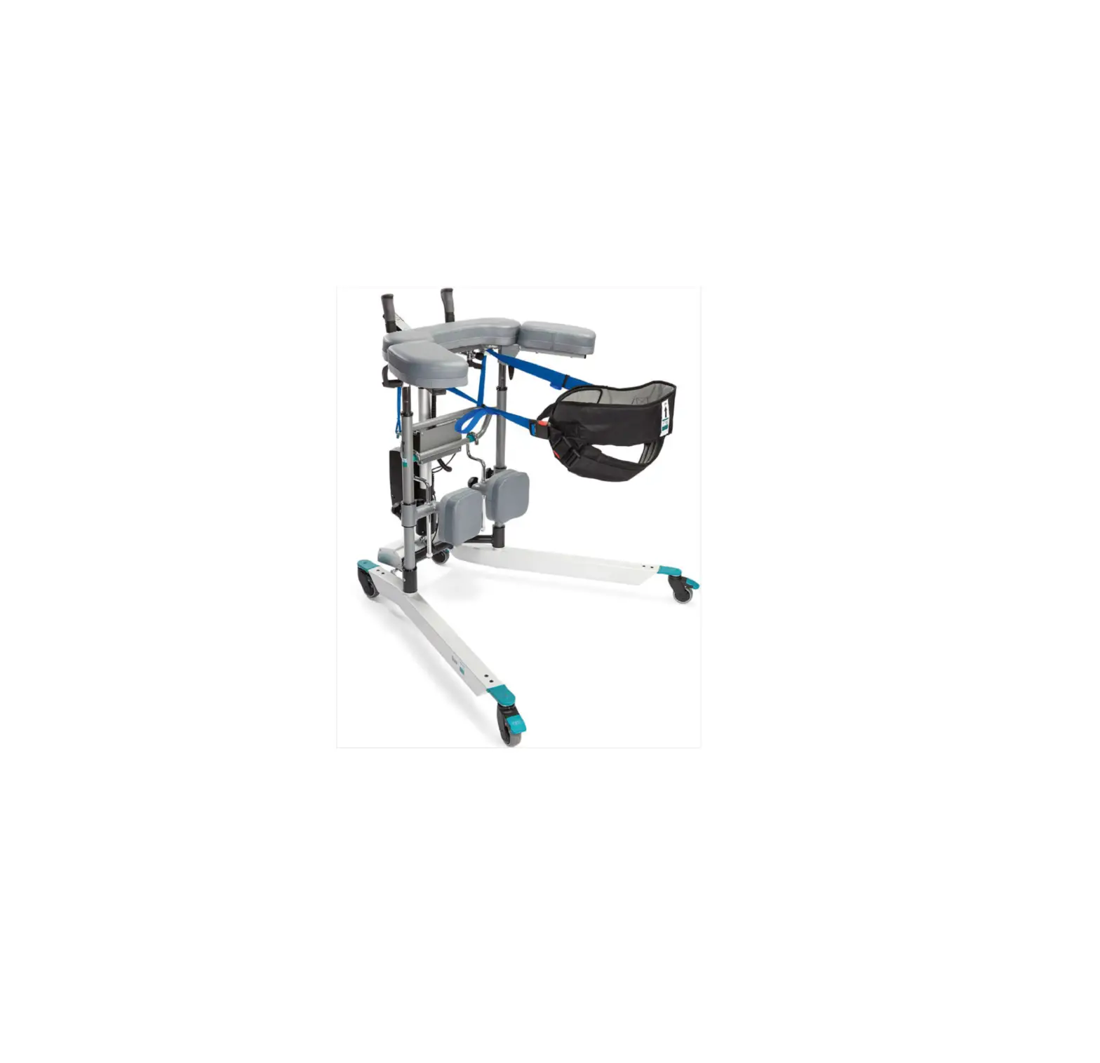
RoMedic Bure Rise and Go DB
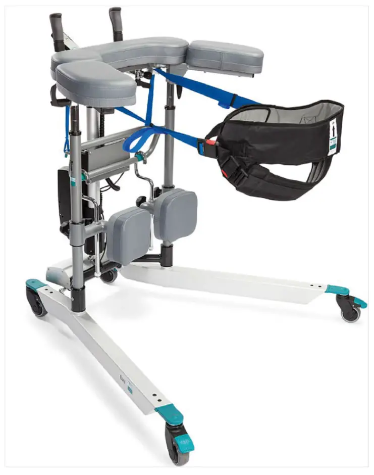
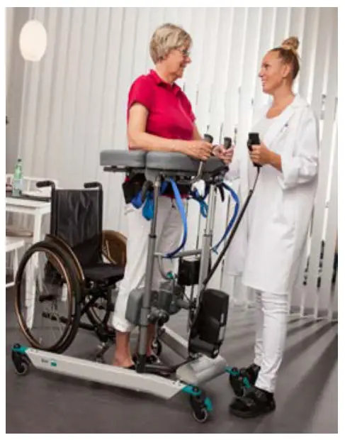
The Bure Rise & Go Double is an electrically operated Walker that is enhanced with a power rise function. The product consists of a Walker and its associated harness and straps.
Intended Use
Walkers are indoor, movable and portable assistive aids, which together with approved accessories are intended to be used for transfer from sitting to standing positions, and walking training. Walkers are to be used by persons with reduced muscular strength, who shall be able to stand and perform simple leg movements. Walkers are to be used for leaning on when walking and standing during early mobilization training. Walkers and accessories are intended for indoor use only in Home Healthcare environment and Professional Healthcare facility environment.
 Contraindications, Precautions and Warnings
Contradictions
- The device may not be used by patients above the maximum weight indicated on the label of the device
Precautions
- Check that the device is used on a dry and flat surface.
- Check the device is correctly mounted/assembled before its first use.
- Check the device after every folding/disassembly after any transport.
- Check height adjustment and leg spreading motions and inspect the actuators full ranges.
- Activate the brakes whenever the device is not in use.
- Check the function of the brakes before use.
- Inspect the device regularly to detect any signs of damage. If there are any visible signs of damage, contact Direct Healthcare Group Customer Service.
- Check that the hand control does not show signs of wear before every use.
- Check that the hand control markings are in accordance with the lifting functions.
- Check the battery status of an electrically operated model before using the device.
- Warranty applies only if repairs or alterations are made by personnel who are authorized by Direct Healthcare Group.
- Ensure that there are no obstacles or people in the way of the device, when moving.
- Handle batteries with care. Do not drop.
- Use only batteries and cables that are intended for the device as instructed by the manufacturer.
- Verify that potential accessories that might be used are properly attached to the device before use.
- Low speed is recommended when moving with the device.
- Take care not to drive the device over thresholds with high speed or force. Approach the threshold with lower speed and communicate the coming threshold to the patient.
- In case of an electrical model of the device, check that the hand control does not show signs of wear before every use
- Keep the instructions for use together with the product so that it can be used as a reference if necessary.
- Beware of moving parts during usage.
- Perform a risk assessment on the patient before using the Walker to ensure they can stand and perform simple movements.
Warnings
- The device may not be used by infants, children or adults who are 146 cm or shorter.
- The caregiver must be able to read and understand the manual/Instructions for Use of the product.
- Caregiver: Never use the device if you have not had a proper training on how to use the device including the accessories.
- Maintenance/Service staff: Never maintain the device if you have not had a proper training on how to use and maintain the device including the accessories.
- It is important to use only approved accessories to prevent unintended detachment of components and subsequently a fall that may lead to patient injury.
- Use careful and gentle maneuvers when moving the device.
- Perform maintenance/service of the device, according to the instructions in the Instruction for Use, at least once every 12 months.
- No parts of the device shall be serviced, while the device is in use
- Accessories must be properly fitted and tested in relation to the patient’s needs and functional ability.
- Special care must be taken when using strong electrical power sources such as diathermy and the like so that diathermy cables are not placed on or near the device. In case of doubt consult with a Direct Healthcare Group representative.
- When lifting the device, only use the denoted handholds. At least two people are required for lifting the device.
- Do not leave a patient unattended when the device is being used.
- The device can not be used by patient alone.
- Never move the walker by pulling on the actuator device.
- The device must not be lowered into water.
- The device must not be cleaned using steam.
- The device must not be left or stored in a damp or humid environment.
- The device must not be charged in a wet room.
- The device must not be used outdoors, only indoors.
- To avoid the risk of electric shock, this equipment must only be connected to a supply mains with protective grounding.
- No modification of this equipment is allowed
- Do not modify this equipment without authorisation of the manufacturer.
- If this equipment is modified, appropriate inspection and testing must be conducted to ensure continued safe use of this equipment.
- Do not use the device while it is charging.
- Do not use the device if any of the cables shows signs of wear and tear.
- Do not put the device in direct sunlight as it may get hot.
- Do not run over the cables with the walker or other devices.
 Always read the user manual
Always make sure that you have the correct version of the manual. The most recent version of all manuals are available for downloading at/from our website: www.directhealthcaregroup.com.
Before use:
- Inspect the packaging for any damage.
- Check for correct product being delivered.
- Check to ensure that the device is free from damage.
- Check if all the parts/components are included in the packaging.
- Check if all approved accessories are included in the package.
- Check if Product Quality Approval document is included in the packaging. Save this document for future contact with manufacturer.
- Make certain the device is properly assembled.
- Check lifting function and bottom-frame adjustment function.
- Check if it is possible to move the device in all directions.
- Check the condition and function of the sling/belt regularly. Always inspect the product after laundering. The occurence of the following must be checked: frays, loose stitches, damage to the fabric, edging, handles, broken buckles. If any of these points apply, the product should be discarded.
Using Bure Walker
Standing up and walk training
- Ask the patient to sit on the edge of the bed or chair. Bring out the walking table and place it in front of the patient. Lock the brakes on the wheels.
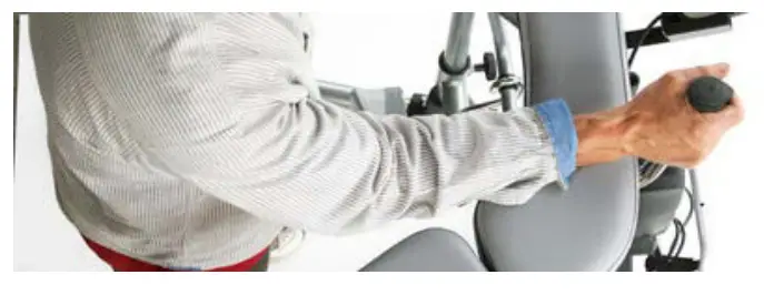
- Ask the patient to place their arms on the armrests. If necessary, ask the patient to move forward on the seat base so that the patient reaches the handles.
- Ask the patient to lean forward. To start raising the walking table, press the UP button on the hand control. Raise the walking table to a desired height.
- Unlock the brakes. Adjust the height of the walking table to a desired position
- Assist the patient while walk training.
Standing up and walk training with MULTI Belt
Because standing up or transporting patients always entails risks we recommend that two people are always present to assist the patient at such times.
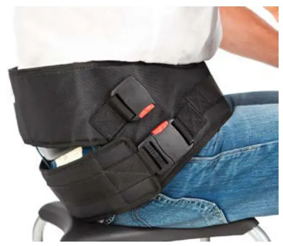
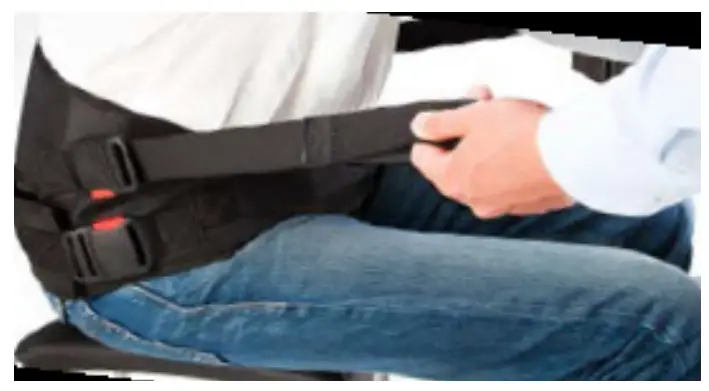
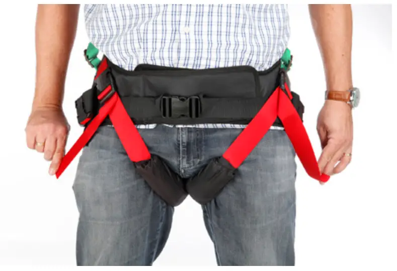
- Fit the harness as low as possible across the hips and bottom with the broad upper part around the hips and the narrow lower part around the bottom. Attach the strap with buckles and tighten it using the adjustable safety belt. Note that the lower part of the harness attached around the patient’s bottom can be opened as required, e.g. for visits to the WC.

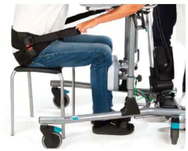
- Place the patient’s legs at a 90˚ angle with their feet on the floor or platform. Adjust the shin supports to fit the patient’s shins; remember to avoid pressure on the patellae and patellar tendons.

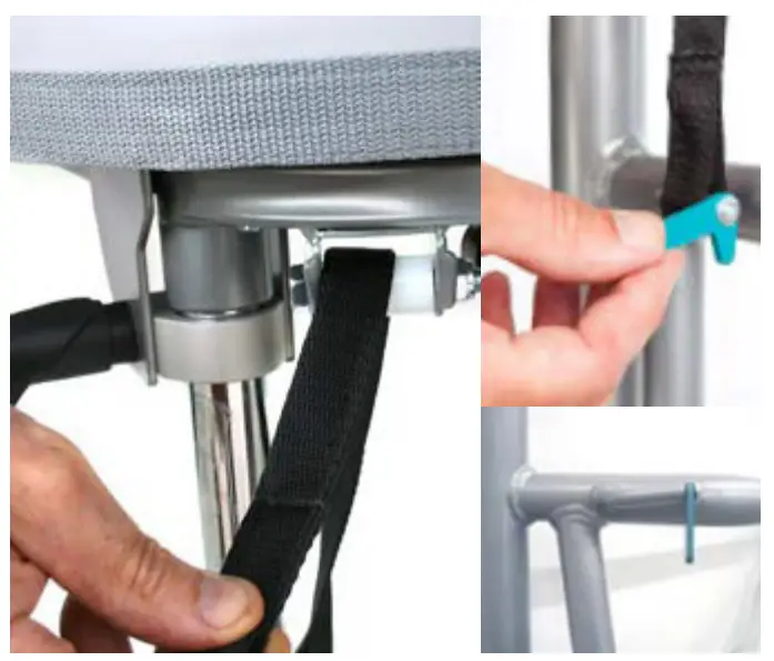
- Thread both attachment belts through the Walker’s frame and the green locking devices. Make sure the belts are threaded completely through the locking devices.
NB: Check especially that the belts are undamaged. Check that belts are not worn or frayed and that the holder and straps are not bent or crooked. If the holder and belts are crooked it is a sign that the product has been overloaded, in which case the frame must be replaced before further use.
NB: Be careful with your fingers when inserting the belt.
- Connect Multi Belt to the attachment belts and tighten them using the loops; the belts must be taught on both sides.

Note: Slide the loop back once the straps have been tightened – this prevents tangling (see fig. 4b).
- Swing the forearm supports to the side; the patient must now grasp the handles without support for the forearms.

- Lock at least two of the Walker’s castors.
- Press UP button on the hand control to lift the patient to the necessary position. Check that the MultiBelt pulls evenly on both sides; if not, adjust immediately.
During the sit-to-stand transfer one caregiver must stand in front of the patient maintaining eye contact with the patient. The other caregiver may stand next to the patient. - In most cases the patient will not achieve a fully upright standing position; encourage the patient to achieve a final upright posture independently or assist the patient by tightening the adjustable harness straps.
- Lower the height of Bure to necessary height and swing the forearm supports back into position to provide support for the patient. If the standing plate is not being used, swing the shin supports away for increased walking room. The Multi Belt may remain attached for enhanced safety.


Using Bure Walker with Gait training Kit 56-388 – KIT and Belt MULTI
The walking training harness is an accessory used for increased safety when walking in the product Bure Rise & Go. The product’s both straps and fastening hooks minimize risks if patients suffer from dizziness or similar issues.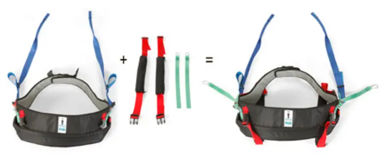
Step 1: Applying the Gait training kit on the patient
The walking training harness is to be used together with Belt MULTI in various sizes. The Gait training kit contains 4 parts made of soft materials: 2 straps with soft padding and 2 straps with fastening hooks.
- Straps with padding are to be applied between the patient’s legs and locked in the intended lock.
- Straps with fastening hook hang loose until patient is secured in Bure Rise & Go (see later step 3)

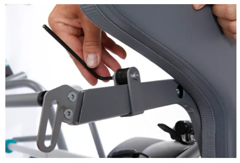
Step 2: Secure attachment modules to the Bure Rise & Go Double
- The attachment modules (2 pcs) is pushed in from the inside on the left and right sides of the armrests under the cushions. We recommend that the modules are placed in the middle of the armrests.
- Lock the module with the supplied screw. Make sure that the module is secured.

Step 3: Securing a patient in Bure Rise & Go Double
If there is a need to further secure the patient, hook the carabiner hooks on the green bands (right and left side) in the fastening module. Tighten the fastening strap so that it is as short as possible.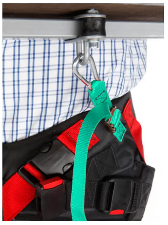
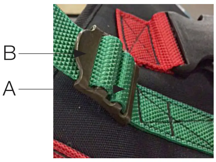
Attaching the fastening straps:
- Green strap is threaded through the buckles from the inside / lower part (A) – up through the buckle & upper part (B).
- Loose straps must be outside the tensioned strap during use

Standing Plate
Attach standing plate by hooks on the main frame of the walker.
Raising/Lowering the Frame The desired height is adjusted with Arrow or Arrow . Adjust bottom frame using arrow or arrow.
Hand Control has charge indicator / battery (low, medium, high) and Service indicator.
Service indicator – flashes red after 11 months’ operation. Constant light (red) after 12 months’ operation. This indicates need of yearly maintenance.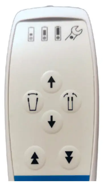
Adjusting the Handles
To adjust handles to the desired position; undo knob, adjust handle, tighten knob.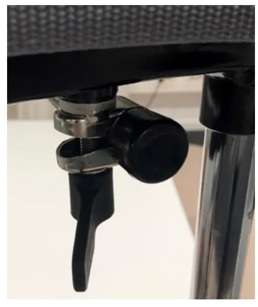
Left and Right Adjustment of Armrests
The armrests can be adjusted sideways for optimal support: the whole arm can be moved in or out and locked with the knob.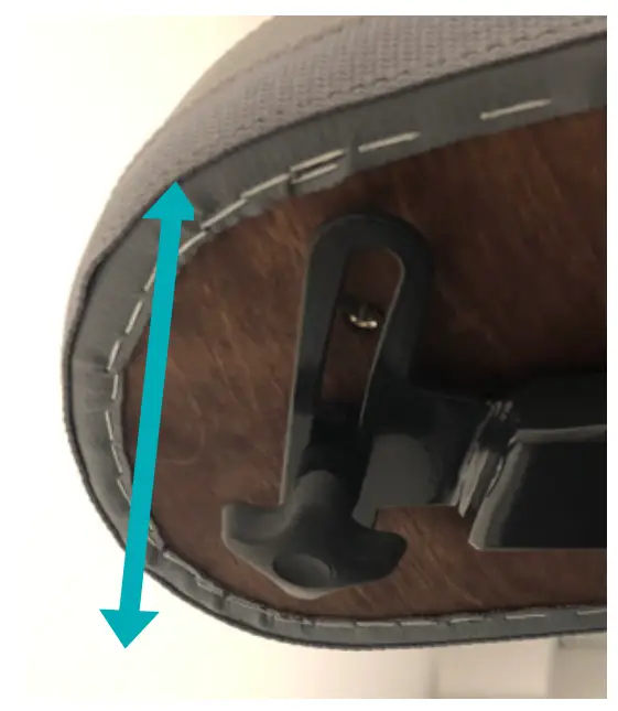
Adjusting the Shin Supports
a – knob for height adjustment.
b – knob for locking shin supports in forward position (when not in use). Support sit.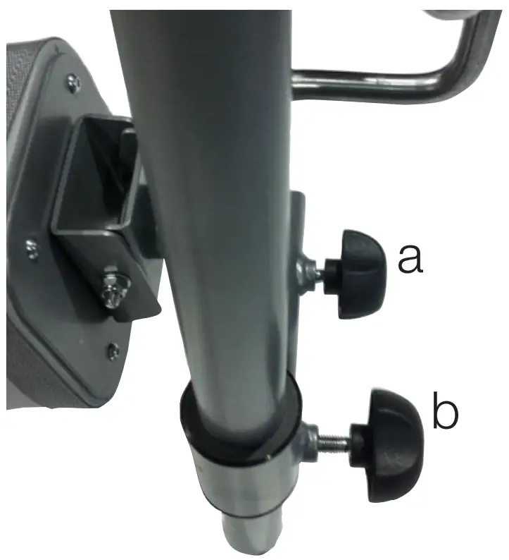
Using the Parking Brakes on Castor Wheels:
When parking the device, activate the parking brake on the lockable castor wheels. Lock the wheels by pressing the green pedal brake down with your foot. To release the brake, press the green protruding part with your foot. The caregiver should assist the patient in activating the parking brake in case the patient cannot activate them him or herself.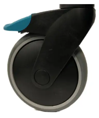
Using Hand Brakes:
Running brakes: Pull the brake levers towards you to reduce speed. You will brake the rear wheel that is located on the same side as the brake lever. If you apply only one of the brakes, the walker will turn to that side. When the lever is released, the braking will stop. Do not use the brakes continuously while the walker is in motion.
Parking brakes: Push the brake levers forwards from you to activate the parking brakes. Be aware that the lever has some resistance before it stops and locks the rear wheel. Pull the brake levers back towards you to release the parking brakes.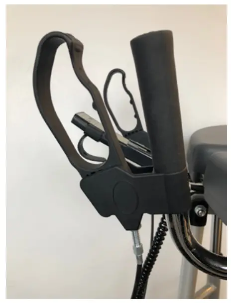
Battery Charging
Battery charging must take place when the device is not in use.
Charging starts automatically when power plug is connected to 230V wall socket.
- LED lights YELLOW during charging (at the same time as the charging indicator on the hand control flashes yellow).
- The LED goes out when the battery is fully charged (the same applies to the charge indicator on the hand control).

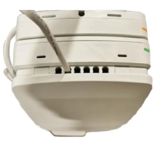
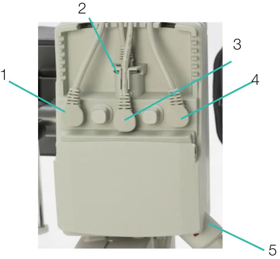
Control box
Control box – LED lights up yellow during operation, is off when the table is not in use. When the control box is connected to the mains, the LED lights up green.
When driving / connected to the mains, the LED lights up yellow. The door on the control box can be opened with a thumb grip..
- Socket for the width adjustment actuator.
- Hand control socket.
- Battery outlet.
- Socket for actuator up / down.
- Socket for plug.

Trouble shooting
If the lifting function cannot be activated, check the following:
- That all cables are properly and securely connected, Pull out the contact and plug it in again firmly.
- That battery charging is not in progress.
- That the battery is charged.
If the device is not working properly, contact your distributor.
If the device makes unusual noises:
- Try to determine the source of the sound. Take the device out of operation and contact your distributor.
Maintenance
- Before maintenance. clean walker according to cleaning instructions.
- The device must undergo thorough inspection at least once per year. Inspection must be performed by authorised personnel and in accordance with Direct Healthcare Group’s instructions.
- Repairs and maintenance may only be done by authorised personnel using original spare parts.
- Power cord may only be replaced by DHG service personnel or technical personnel trained by DHG.
- DHG can provide, upon request necessary technical information in order to assist maintenance and repair of the device.
| Check that | Action if a problem is noticed |
| Frame | |
| There is no mechanical damage. | If mechanical damage is present, contact DHG Customer Services. |
| There are no scratches. | Touch up as necessary. |
| End plugs/lower frame fitted and not damaged. | Fit new end plugs. |
| Armrest | |
| Armrests are intact | Replace if damaged. |
| Armrest widening is functional. | Replace lock knob, see parts section. |
| Handle | |
| Grips are not damaged. | Replace handle grips. |
| Handle adjustment is functional. | Adjust lock screws/plates as required. |
| Electronics | |
| Check that the charging cable is connected to the control box. | Fit new charging cable; this must always be connected to the control box. |
| Check that the hand control is connected to the control box. | Connect or fit new hand control as required. Tighten; replace with new fasteners as required. |
| Check that the battery, actuators and control box are not loose. | If any part needs to be replaced refer to the wiring diagram in the control box wiring section. |
| Height adjustment | |
| Raising and lowering are functional. | Fit new guide sleeves (in frame) or end plugs (in chrome tubes) as required. |
| The walker feels stable at maximum height and width. | Tighten all nuts and bolts. |
| There is no movement between the vertical frame and bottom frame. | Tighten all nuts and bolts. |
| Height adjustment clamps lock. | Replace clamps. |
| The electric actuator fitting must be free from movement. | Tighten all nuts and bolts; replace bolts and nuts if necessary. |
| Height adjustment via hand control is functional. The electric actuator must run smoothly at a constant speed. | Check that the battery/hand control/ actuator are connected according to the control box wiring section. Charge the battery. See parts section |
| Castors and brakes | |
| Castors roll easily, tread not damaged. | Replace castors. |
| The castors are firmly fastened to the lower frame. | Tighten the castor bolt and nut. Use thread locker. |
| Castor brakes functional on all castors. Handbrake functional. | Replace castors or handbrake assembly. Clean and adjust the brake. The castors are sealed and it is not recommended to dismantle them; instead, replace the whole castor assembly. |
Storage and transportation
The walker should be transported and stored in 5°C to 50°C and in normal humidity, 20% to 80% non-condensing.
The air pressure should be between 700 and 1060hPa. Leftmost symbol indicates storage and transportation. Let the walker reach room temperature before the batteries are charged or the walker is used. The walker should not be stored so that it is exposed to dust, or so that the battery or gas piston is exposed to direct sunlight.
Operation
The operating environment should be 5°C to 40°C, relative humidity 20% to 80% non-condensing, and atmospheric pressure 700 to 1060 hPa. See also Technical specification below. Leftmost symbol indicates operating condition.
Cleaning and disinfection
After every use:
Clean the walker armrests and handles. Wipe using a mild soap solution/surface disinfectant. The product is not corrosion proof.
Weekly and possibly more often depending on frequency of use:
If necessary, clean the whole walker with a cloth with warm water or a soap solution and check that the castors are free from dirt and hair. The electronic components (battery, control box, hand control, actuators, cables) should be cleaned with a damp cloth only. To avoid degreasing of the piston rods, the actuators should be retracted to minimum stroke and without load before cleaning. Ensure that the device is dried thoroughly after cleaning.
If disinfection is needed:
70% ethanol, 45% isopropanol or similar should be used.
Do not steam clean due to risk of corrosion.
Do not use cleaning agents containing phenol or chlorine, as this could damage the materials.
In environments with high risk of infections use the walker with PU-cushions (Accessory number 57-366-L, 57-366- R and 57-365)
General Maintenance for gait training Sling:
Read the product label.
Do not use rinsing agent.
To prolong product life, avoid tumble-drying.
Recycling/Disposal
When the product is no longer usable it should be recycled in accordance with legislation and regulations in the country concerned. All electrical parts including batteries must be removed and recycled as electrical components.
Ask your local recycling station for further information about how the different materials in the product (metals, plastics, electronics, textiles) should be recycled. Used batteries can also be returned to Direct Healthcare Group or a Direct Healthcare Group distributor for recycling.
Technical Specifications
| Control box | Linak, voltage 100V/240V, Max 1.5A, 50/60 Hz, IPX6, Class II (Double insulated) |
| Batteries | Linak, 25,2V/2,1Ah, sealed,Li-Ion, 300mA IPX6, Cable length 200mm |
| Lifting Actuator | Linak, DC 24 V, 4,3A, IPX6. Duty cycle: Max 10% or 2 minutes continuous use followed by 18 minutes not in use, Push: 2000N. Stroke 400mm +/-2 mm |
| Widening Actuator | Linak, DC 24 V, 3A, IPX6. Duty cycle: Max 10% or 2 minutes continuous use followed by 18 minutes not in use, Push/Pull: 1200N. Stroke 180mm +/-2 mm |
| Hand Control | Cable length coiled 600 mm, IPX6 |
| IP class | IPX5 |
| Material | Steel |
| Castors | 125/100/75mm |
| Weight | 42 kg |
| Dimensions | For dimensions, see “7. Dimensions” page |
| Expected Service life | Walkers: 8 years Textile products: 2 years under normal use. Two wash cycles a week are considered as normal use. However, the total lifetime is dependent on the use, maintenance and storage of the product. |
| Max patient weight | 150 kg / 330 Ibs |
| Operating environment | 5 °C to 40°C, relative humidity 20% to 80% non-condensing, and atmospheric pressure 700 to 1060 hPa. |
| Storage and transportation environment | 5 °C to 50 °C, relative humidity 20% to 80% non-condensing, and atmospheric. Environment pressure 700 to 1060 hPa. |
| Materials in contact with human skin | Materials that patient and operator/caregiver are exposed to during usage of the product for prolonged time: Meditap B-365 (synthetic leather cushions) P x Polyurethane (on PU cushions) P Dryflex (handles) P PA6 + 20% GF (brake lever) P Hand control C X |
| Applied parts: | Armrest P Handles P Knee pad P Foot rest support P Foot rest support clamps C Handles adjusting knobs C Hand controller and its holder. C Handles to adjust the armrest width. C Hand control C Charger C Charger cable C Footplate P |
Accessories
| Part number | Description |
| 58-328-1 | Heel strap Standing plate |
| 56-336-4 | Oxygen holder |
| 56-338 | Drip rod complete with attachment |
| 56-337 | Side support, adjustable |
| 56-337-PU | Side support, adjustable PU |
| 56-352 | Lower Leg Support |
| 56-388 | Gait training kit |
| 56-388-KIT | Gait training kit incl. brackets Multi Rise&Go |
| 57-368-4 | Guide handle |
| 56-389 | Soft basket with attachment |
| 56-333-DB | Standing plate Short/2015, Bure DB, Rise DB |
| 56-333/SW-DB | Standing plate Short/2015, SW, Bure DB, Rise DB |
| 56-383-DB | Standing plate Long/2015, Bure DB, Rise DB |
| 56-383/SW-DB | Standing plate Long/2015, SW, Bure DB, Rise DB |
| 56-339/75-2-0 | Manual brake, 75mm wheel, 2 handles |
| 56-339/75-2-1 | Manual brake, 75mm wheel, 1 handle |
| 56-339-2-0 | Manual brake, 2 handles |
| 56-339-2-1 | Manual brake, 1 handle |
| 56-339-4-0 | Manual brake/2016, 2 handles, Bure Rise&Go DB |
| 56-339/75-4-0 | Manual brake/2016, 75mm, 2 handles, Bure Rise&Go DB |
| 56-339/75-4-1 | Manual brake/2016, 75mm, 1 handle, Bure Rise&Go DB |
| 56-305 | Touch-up paint Bure, Silver 8 |
| 56-306 | Touch-up paint Bure, Dark grey RAL 7021 |
| 56-384-MULTI-XS | Belt MULTI -XS, Rise&Go kit |
| 56-384-MULTI-S | Belt MULTI -S, Rise&Go kit |
| 56-384-MULTI-M | Belt MULTI -M, Rise&Go kit |
| 56-384-MULTI-L | Belt MULTI -L, Rise&Go kit |
| 56-384-MULTI-XL | Belt MULTI -XL, Rise&Go kit |
| 7215 | Return knee pads padding |
Product label
UDI (Unique Device Identification) can be found within the barcode human readable text. It contains.
(01) EAN code
(11) Date of Manufacture. The date is in the format YYMMDD
Y = Year, M = Month and D = Date.
(21) Serial Number displayed as five digit code.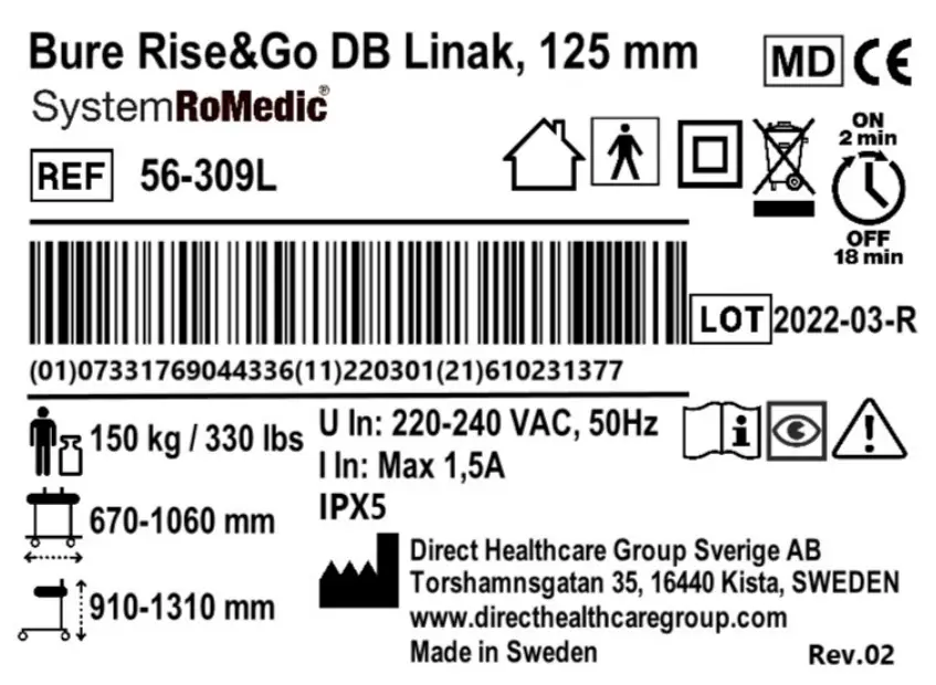
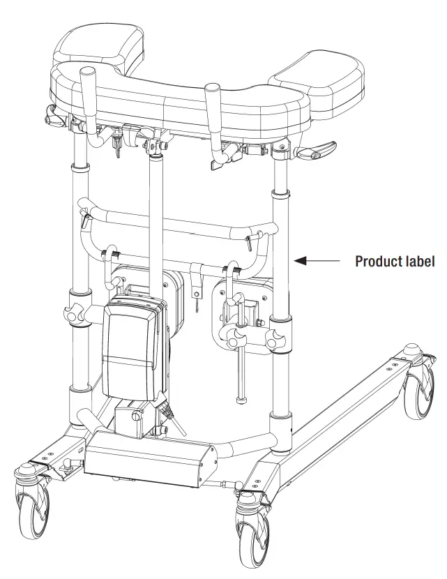
Table of Symbols
 | This product complies with the requirements of the Medical Device Regulation 2017/745 |  | Visual Inspection |
 | Medical Device |  | Read the manual |
 | Caution |  | Product Code |
 | Legal manufacturer Direct Healthcare Group Sverige AB |  | Batch Code |
 | Type BF applied parts, according to the degree of protection against electric shock |  | The device is intended for indoor use |
 | WEEE Symbol May not be discarded in domestic waste |  | Class II Equipment |
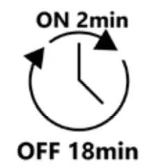 | Duty Cycle: 2 min in active (ON) mode. 18 min in rest (OFF) mode. |  | Maximum patient weight |
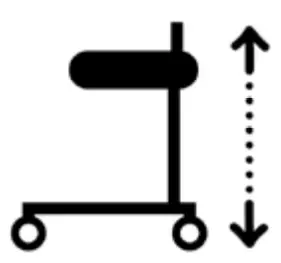 | Walker Height | 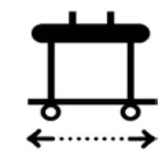 | Walker Width |
 | Do not step on the device |  | Refer to instruction manual (IFU) |
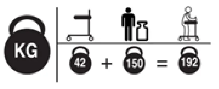 | Weight (mass) of the device, the Maximum Patient Weight, and total sum. All in kg. | ||
How To Report A Serious Incident
Any serious incident that has occurred in relation to the device should be reported to the manufacturer and the MHRA or another competent authority of the country in which the user and/or patient is established.
UK
[email protected]
T: +44 (0) 800 043 0881
F: +44 (0) 845 459 9832
Other:
[email protected]
Electromagnetic Compatibility (EMC)
Electromagnetic emissions and test levels
The product is intended to be used in the stated environments with electromagnetic levels as specified below. The caregiver and/or user of the product assure that the product is used in such an environment.
| Emission test | Standards | Compliance |
| RF emissions | CISPR 11 | Group 1 |
| RF emissions | CISPR 11 | Class B |
| Hamonic current emissions | IEC 61000-3-2 | Class A |
| Voltage fluctuations and Flicker emissions | IEC 61000-3-3 | Complies |
Electromagnetic Immunity
Acceptance criteria for the EMC pass criteria is unintentional movement above ±10mm is not allowed. The product is intended to be used in the stated environments with electromagnetic levels as specified below. The caregiver and/or user of the product assure that the product is used in such an environment.
| Radiated Fields in close proximity, Immunity test and compliance. Standard: IEC 61000-4-39 | |||
| Dwell time: 3 sec | |||
| Test levels (A/m) | Modulation Pulse modulation | Mod. Frequency (kHz) | Test Frequency |
| 8 | CW | CW | 30 kHz |
| 65 | 50% Duty cycle | 2.1 | 134.2 kHz |
| 7.5 | 50% Duty cycle | 50 | 13.56 MHz |
| Immunity test | Basic EMC standard or test method | IEC 60601-1-2 Edition 4 Test levels and compliance | |
| Professional healthcare facility environment | Home healthcare environment | ||
| Surge | IEC 61000-4-5 | ± 0.5 kV, ± 1 kV | |
| Voltage dips | IEC 61000-4-11 | 0% UT; 0.5 cycle At 0°, 45°, 90°, 135°, 180°, 225°, 270° and 315° | |
| 0% UT; 1 cycle and 70% UT; 25/30 cycles. Single phase: at 0° | |||
| Voltage Interruptions | IEC 61000-4-11 | 0% UT ; 250 / 300 cycle | |
| Conducted disturbances induced by RF fields | IEC 61000-4-6 | 6V in ISM bands between 0.15 MHz and 80 MHz 80% AM at 1 kHz | 6V in ISM and amateur bands between 0.15 MHz and 80 MHz 80% AM at 1 kHz |
| Dwell time: 3 sec Frequency step size: 1% | |||
| Radiated RF Electromagnetic fields | IEC 61000-4-3 | 3 V/m 80 MHz – 2.7 GHz 80% AM at 1 kHz | 10 V/m 80 MHz – 2.7 GHz 80% AM at 1 kHz |
| Dwell time: 3 sec Frequency step size: 1% | |||
| Electrical fast transients / burst | IEC 61000-4-4 | ± 2 kV 100 kHz repetition frequency | |
| RATED Power frequency magnetic field | IEC 61000-4-8 | 30 A/m 50 Hz or 60Hz | |
| Electrostatic Discharge (ESD) | IEC 61000-4-2 | Contact: ± 8 kV Air: ± 2 kV, ±4 kV, ± 8 kV, ± 15 kV Number of discharges: 10 for each polarity | |
| Radiated Radio – Frequency, Proximity fields from wireless communication equipment & compliance. (Dwell time: 3 sec.) Standard: IEC 61000-4-3 | |||||
|
Spot Frequencies | Test Frequency (MHz) | Band (MHz) | Service | Modulation | Immunity test levels (V/m) |
| 385 | 380 to 390 | TETRA 400 | Pulse modulation 18 Hz | 27 | |
| 450 | 430 to 470 | FMRS 460, FRS 460 | FM ± 5 kHz Deviation 1 kHz sine | 28 | |
| 710 | 704 to 787 | LTE Band 13, 17 | Pulse modulation 217 Hz | 9 | |
| 745 | |||||
| 780 | |||||
| 810 | 800 to 960 | GSM 800/900, TETRA 800, iDEN 820, CDMA 850, LTE Band 5 | Pulse modulation 18 Hz | 28 | |
| 870 | |||||
| 930 | |||||
| 1720 | 1700 to 1990 | GSM 800/900, TETRA 800, iDEN 820, CDMA 850, LTE Band 5 | Pulse modulation 217 Hz | 28 | |
| 1845 | |||||
| 1970 | |||||
| 2450 | 2400 to 2570 | Bluetooth, WLAN, 802.11 b/g/n, RFID 2450, LTE Band 7 | Pulse modulation 217 Hz | 28 | |
| 5240 | 5100 to 5800 | WLAN 802.11 a/n | Pulse modulation 217 Hz | 9 | |
| 5500 | |||||
| 5785 | |||||
| Other Identified frequencies | 433 | – | – | Pulse modulation 2 Hz | 3 |
| – | 860-960 | – | Pulse modulation 2 Hz | 54 | |
| 2450 | – | – | Pulse modulation 2 Hz | 54 | |
Dimensions
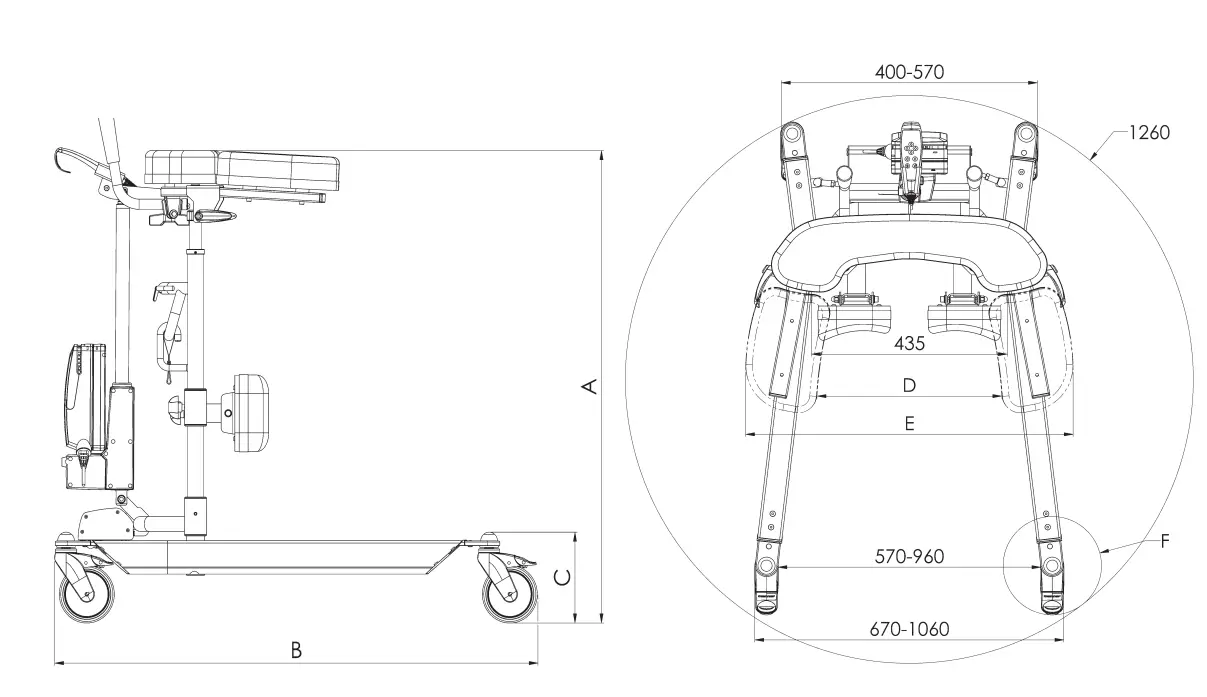
| A | B | C | D | E | F | |
| Wheel diameter | Armrest height. (PU option is 30mm lower) Brake option 5mm lower | Length | Leg clearance (Brake option 5mm lower) | Armrest inner clearance | Armrest outer clearance PU 60mm wider | Wheel area diameter |
| 56-309 Bure R&G | ||||||
| 125mm | 910-1310 | 1100 | 195 | 210-560 | 540-900 | 218 |
| 100mm | 890-1290 | 1085 | 175 | 190 | ||
| 75mm | 860-1260 | 1080 | 145 | 188 | ||
Parts
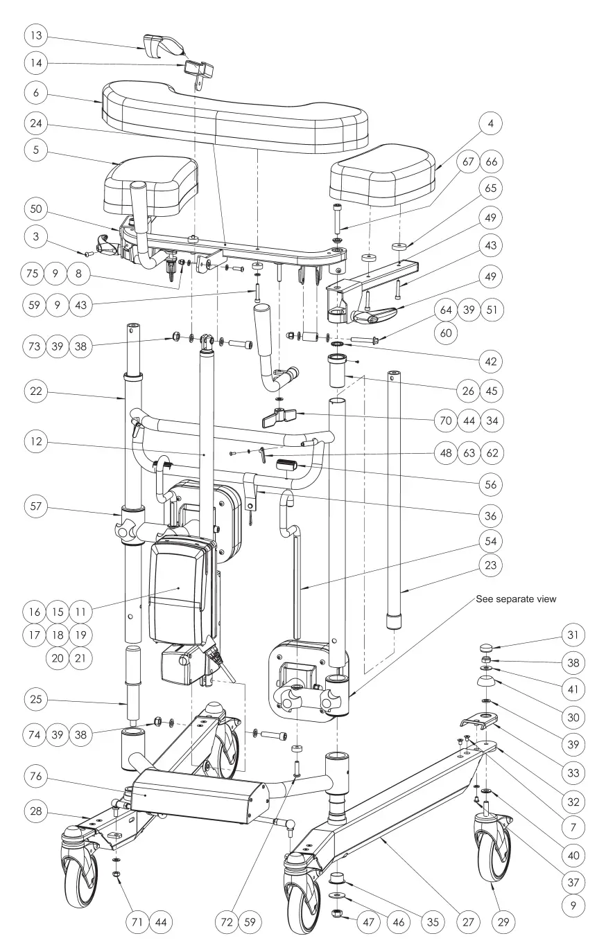
Parts List
| No. | Art No. | Description | No. | Art No. | Description |
| 1 | 58-309 | Leg support vinyl connection | 26 | 57-310 | Middle frame bushing |
| 2 | 58-312 57-367 | Leg support pad vinyl Rise&Go Leg support pad PU Rise&Go | 27 | 58-355-L | Bottom Beam Left Rise&Go DB |
| 3 | 57-887 | Screw K6S M6x16 | 28 | 58-355-R | Bottom Beam Right Rise&Go DB |
| 4 | 58-306-L 57-366-L | Armrest Outer pad Left Rise&Go Armrest Outer pad PU Left Rise&Go | 29 | 57-049 56-360 57-319 56-357 56-387 57-051 | Castor wheel 125mm brake Castor wheel 125mm w/o brake Castor wheel 100mm brake Castor wheel 100mm w/o brake Castor wheel 75mm brake Castor wheel 75mm w/o brake |
| 5 | 58-306-R 57-366-R | Armrest Outer pad Right Rise&Go Armrest Outer pad PU Right Rise&Go | 30 | 57-775 | Dome cover wheel |
| 6 | 58-305 57-365 | Armrest Center Pad Rise&Go Armrest Center Pad PU Rise&Go | 31 | 57-776 | Dome cover wheel top |
| 7 | 57-885 | Screw MF6S M6x10 | 32 | 58-354-1 | Wheel attachment |
| 8 | 57-879 | Cap nut M6 | 33 | 58-360 | Cover Wheel attachment |
| 9 | 57-805 | Washer BRB 6,4x12x1,6 | 34 | 56-353 | Bure Handle assy |
| 10 | 14103 | Assembly kit Linak 200kg DB | 35 | 58-338 | Bushing middle frame |
| 11 | 58-397 | Control box Linak LA31 220V | 36 | 56-308 | Cable holder Bure charger |
| 12 | 58-400 | Actuator Linak LA31 2000N | 37 | 57-639 | Screw K6S M6x8 |
| 13 | 57-041-7 | Holder hand control Linak HB41 | 38 | 57-817 | Lock nut CL6 M10 |
| 14 | 58-411-X2 | Hand control Linak HB30 | 39 | 57-825 | Washer 10,5×18×2 |
| 15 | 58-402 | Battery Linak BA21 LiOn | 40 | 57-848 | Nordlock 10,7x21x2,5 |
| 16 | 58-403 | Cable Linak Battery BA21 | 41 | 57-787 | Washer 10x25x1,5 |
| 17 | 58-404 | Blind plug Linak control box | 42 | 57-811 | Serrated lock washer M16 |
| 18 | 58-405 | Bracket Linak Control box/Battery | 43 | 57-804 | Screw MC6S M8x35 |
| 19 | 7427111 | Ferrite sleeve | 44 | 57-806 | Washer 8.4x16x1.5 |
| 20 | 58-409 | Cable widening actuator Linak LA23 1000mm | 45 | 57-812 | Tapping screw RXS 2,9×4,5 |
| 21 | 58-408 | Cable lock Linak LA23 | 46 | 57-769 | Washer12,5x35x2 |
| 22 | 58-351 | Middle Frame Rise&Go | 47 | 57-766 | Lock nut CL6 M12 |
| 23 | 58-311 | Telescope inner pipe | 48 | 58-322 | Band washer green Rise & Go |
| 24 | 58-363 | Armrest frame center Part Rise&Go | 49 | 58-304-L | Armrest Hinge Left Rise&Go |
| 25 | 58-353 | Axis middle frame | 50 | 58-304-R | Armrest Hinge Right Rise&Go |
| 51 | 57-880 | Cap nut M8 | 64 | 57-859 | Screw M6SF M8x50 |
| 52 | 57-867 | Screw M8x90 MC6S | 65 | 57-733 | Washer Nylon 30x8x7 Rise&Go |
| 53 | 57-720 | Bushing Leg support bracket | 66 | 58-321 | Bushing Armrest Rise&Go |
| 54 | 58-310-1 | Leg support hanger | 67 | 57-968 | Screw MC6S M10x55 |
| 55 | 58-308-1-L | Leg Support Bracket 14mm LEFT Rise&Go | 68 | 57-839 | Star knob handle |
| 56 | 58-329 | Clip PE Soft Rise&Go | 69 | 57-710 | Star knob handle |
| 57 | 58-308-1-R | Leg Support Bracket 14mm RIGHT Rise&Go | 70 | 57-917 | Wing nut M8 |
| 58 | 58-302 | Bushing PA6 Black | 71 | 57-801 | Lock nut M8 |
| 59 | 57-734 | Washer 22×6,5×8 | 72 | 57-881 | Screw K6S M8x30 |
| 60 | 57-713 | Roll Strap guide Rise&Go | 73 | 57-816 | Screw MC6S M10x40 |
| 61 | 58-323 | Lock bushing leg support | 74 | 57-884 | Screw MC6S M10x45 |
| 62 | 57-857 | Screw K6S M4x10 | 75 | 57-864 | Screw K6S M6x20 |
| 63 | 57-858 | Washer BRB 8×4,3×0,8 | 76 | 57-725 | Widening assembly Linak Bure Double, R&G |
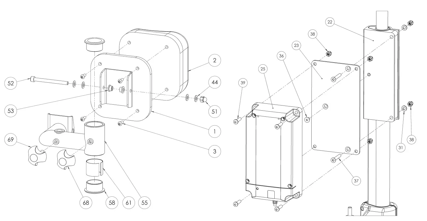
| Art No. | Description |
| 57-725 | Widening assembly Linak Bure Double, R&G |
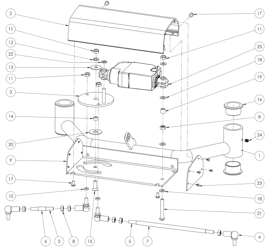
| No. | Art No. | Description | No. | Art No. | Description |
| 1 | 58-352 | Crossection bottom Bure double | 14 | 57-760 | PVC Spacer 8x12x6,4 |
| 2 | 58-356 | Housing Turn motor | 15 | 57-765 | Screw MF6S M8x25 |
| 3 | 58-364 | Turning wheel | 16 | 58-302 | Crossection bottom bushing |
| 4 | 57-763 | Ball joint angled M8 | 17 | 57-818 | Screw K6S M6x10 |
| 5 | 58-381 | Threaded steel rod M8 | 18 | 57-806 | Washer 8.4x16x1.5 |
| 6 | 58-380-R | Turning tube right | 19 | 57-778 | Washer Nylon 05-8-12-10 |
| 7 | 58-380-L | Turning tube left | 20 | 57-774 | Washer Nylon 13x34x1,5 |
| 8 | 57-876 | Nut M6M M8 | 21 | 57-882 | Screw K6S 10.9 M8x55 |
| 9 | 58-358 | Cover Housing Turn motor | 22 | 57-767 | Washer Starloc 8×15,3 |
| 10 | 57-777 | Washer nylon 05-8-12-3 | 23 | 57-771 | Screw RXS 3,5×6,5 |
| 11 | 57-801 | Lock nut M8 | 24 | 57-875 | Set screw SK6S M8x6 |
| 12 | 57-836 | Spring lock washer M8 | 25 | 58-407 | Actuator widening Linak LA23 Bure DB, Rise |
| 13 | 57-826 | Washer 8,4x29x1,5 | |||
Product Overview
| Article number | Product name |
| 56-309L | Bure Rise&Go DB Linak, 125 mm |
| 56-309L-PU | Bure Rise&Go DB Linak, 125 mm, PU |
| 56-309L-B/0 | Bure Rise&Go DB Linak, 125 mm, handbrakes |
| 56-309L-B/0-PU | Bure Rise&Go DB Linak, 125 mm, handbrakes, PU |
| 56-309L-B/1 | Bure Rise&Go DB Linak, 125 mm, 1 handbrake |
| 56-309L-B/1-PU | Bure Rise&Go DB Linak, 125 mm, 1 handbrake, PU |
| 56-309L-PU-RS | Bure Rise&Go DB Linak, 125mm, PU, direction lock |
| 56-309L-UK | Bure Rise&Go DB Linak, 125mm, UK |
| 56-309L-PU-UK | Bure Rise&Go DB Linak, 125 mm, PU, UK |
| 56-309L-B/0-UK | Bure Rise&Go DB Linak, 125 mm, handbrakes, UK |
| 56-309L-B/0-PU-UK | Bure Rise&Go DB Linak, 125 mm, handbrakes, PU, UK |
| 56-309L-B/1-UK | Bure Rise&Go DB Linak, 125 mm, 1 handbrake, UK |
| 56-309L-B/1-PU-UK | Bure Rise&Go DB Linak, 125 mm, 1 handbrake, PU, UK |
| 56-309L-AUS | Bure Rise&Go DB Linak, 125mm, AUS |
| 56-309L-B/0-PU-AUS | Bure Rise&Go DB Linak, 125mm, handbrakes, PU, AUS |
| 56-309L-B/0-AUS | Bure Rise&Go DB Linak, 125mm, handbrakes, AUS |
| 56-309L/75 | Bure Rise&Go DB Linak, 75mm |
| 56-309L/75-PU | Bure Rise&Go DB Linak, 75mm, PU |
| 56-309L/75-PU-RS | Bure Rise&Go DB Linak, 75mm, PU, direction lock |
| 56-309L/75-B/0 | Bure Rise&Go DB Linak, 75 mm, handbrakes |
| 56-309L/75-B/0-PU | Bure Rise&Go DB Linak, 75 mm, handbrakes, PU |
| 56-309L/75-B/1 | Bure Rise&Go DB Linak, 75 mm, 1 handbrake |
| 56-309L/75-B/1-PU | Bure Rise&Go DB Linak, 75 mm, 1 handbrake, PU |
| 56-309L/75-UK | Bure Rise&Go DB Linak, 75mm, UK |
| 56-309L/75-PU-UK | Bure Rise&Go DB Linak, 75mm, PU, UK |
| 56-309L/75-B/0-UK | Bure Rise&Go DB Linak, 75mm, handbrakes, UK |
| 56-309L/75-B/0-PU-UK | Bure Rise&Go DB Linak, 75mm, handbrakes, PU, UK |
| 56-309L/75-B/1-UK | Bure Rise&Go DB Linak, 75mm, 1 handbrake, UK |
| 56-309L/75-B/1-PU-UK | Bure Rise&Go DB Linak, 75mm, 1 handbrake, PU, UK |
Main configuration is following: 125 mm wheels, no handbrakes, cushions made of synthetic leather, regular hand control, no special features. Following variations are possible:
- 125/100/75 mm – indicates diameter of wheels
- Handbrakes – indicates that the model has a handbrake on both handles
- 1 handbrake – indicates that the model has only 1 handbrake on one of the handles
- UK, AUS, US – models designed specifically for these countries
- Linak- means that the model includes electronics from Linak for adjust of the height
- Gas – means that the model includes hydraulic system for adjustment of the height
- Manual – means that the height of the model is adjusted manually
- Plus – means that the model includes a Plus hand control
- Low – means that the model has lower middle frame for shorter patients
- S – means that the model is more narrow than the standard model
- PU – means that the model includes cushions made of Polyurethane
Simple Solutions For Great Results
SystemRoMedic® is the name of Direct Healthcare Group’s unique easy transfer concept, the market’s widest and most comprehensive range of clever, easy-to-use and safe transfer and lifting aids designed to make life easier, both for the user and for the caregiver. SystemRoMedic® is a complete solution that provides for the majority of patient transfer or manual handling requirements. From the simplest to the most complex scenarios, from the lightest to the heaviest. The concept encompasses assistive devices for four different categories of transfers:
- Transfer, assistive devices for manual transfers of users between two locations.
- Positioning, assistive devices for manual repositioning of users within the same location.
- Support, assistive devices for mobility support e.g., during sit-to-stand or gait training.
- Lifting, assistive devices for manual and mechanical lifting of users.
Improved work environment, improved quality of care and cost savings
The philosophy behind SystemRoMedic® is focused on the prevention and reduction of occupational injuries while allowing users to experience a greater sense of independence and dignity. Through a unique combination of training and a complete range of efficient transfer aids, SystemRoMedic® offers improvement of both work environment and quality of care and, at the same time, achieves significant cost savings.
Always make sure that you have the correct version of the manual
The most recent version of all manuals are available for downloading at/from our website; www.directhealthcaregroup.com
For questions about the product and its use
Please contact your local Direct Healthcare Group and SystemRoMedic® representative. A complete list of all our partners with their contact details can be found on our website; www.directhealthcaregroup.com.
Customer Support
Direct Healthcare Group Sverige AB
Torshamnsgatan 35,
SE-164 40 Kista, Sweden
Tel: +46 (0)8-557 62 200
[email protected]
www.directhealthcaregroup.com