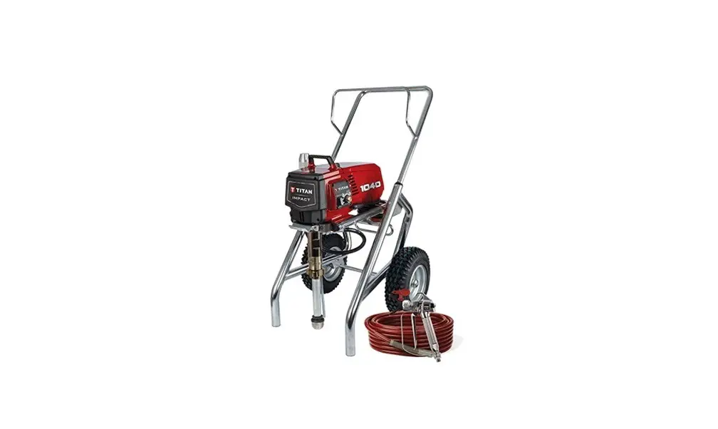
TITAN Impact 1040 Airless High-Pressure Spraying Unit Owner’s Manual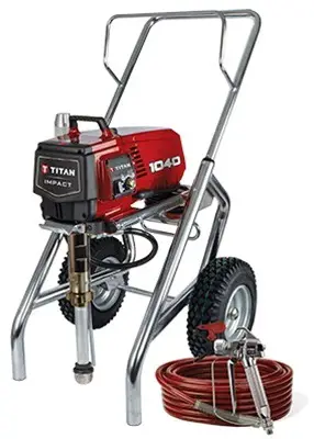
SPECIFICATIONS
| Name | 1040 |
| Model # | 0552600 |
| Specifications | |
| Gallons per minute | 1.15 (4.35 LPM) |
| Maximum tip sizes | 1 gun – 0.033” |
| 2 gun – 0.021” | |
| Maximum pressure | 3300 PSI (22.8 MPa) |
| Weight | 98 lbs. |
| Maximum hose length | 300’ |
| Power | 2.5 HP Brushless DC Motor, 100~120V AC, 50/60Hz, 15A |
| Generator requirement | 5000 Watt (disable idle-down feature) |
| Included accessories | |
| Spray gun | RX-Pro |
| Spray hose | 50’ (15 m) P/N 316-505 |
| Spray filter | 60 mesh, P/N 0089958 |
| Literature | |
| Operation manual (Form No. 0552896) | English / French / Spanish included with product and available online at www.titantool.com |
| Service manual (Form No. 2424937) | English / French / Spanish available online at www.titantool.com |
| RX-Pro manual (Form No. 0538801) | All languages included with product and available online at www.titantool.com |
| Compliance | |
 | Conforms to UL STD 1450 Certified to CSA STD C22.2 No. 68 |
SAFETY REGULATIONS FOR AIRLESS SPRAYING
EXPLANATION OF SYMBOLS USED
This manual contains information that must be read and understood before using the equipment. When you come to an area that has one of the following symbols, pay particular attention and make certain to heed the safeguard.
 This symbol indicates a potential hazard that may cause serious injury or loss of life. Important safety information will follow.
Attention
This symbol indicates a potential hazard to you or to the equipment. Important information that tells how to prevent damage to the equipment or how to avoid causes of minor injuries will follow.
 Danger of skin injection
 Danger of fire from solvent and paint fumes
 Danger of explosion from solvent, paint fumes and incompatible materials
 Danger of injury from inhalation of harmful vapors
 Danger of electric shock
![]() Notes give important information which should be given special attention.
Notes give important information which should be given special attention.
GROUNDING INSTRUCTIONS
This product must be grounded. In the event of an electrical short circuit, grounding reduces the risk of electric shock by providing an escape wire for the electric current. This product is equipped with a cord having a grounding wire with an appropriate grounding plug.
The plug must be plugged into an outlet that is properly installed and grounded in accordance with all local codes and ordinances.
WARNING – Improper installation of the grounding plug can result in a risk of electric shock.
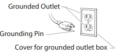
If repair or replacement of the cord or plug is necessary, do not connect the green grounding wire to either flat blade terminal. The wire with insulation having a green outer surface with or without yellow stripes is the grounding wire and must be connected to the grounding pin.
Check with a qualified electrician or serviceman if the grounding instructions are not completely understood, or if you are in doubt as to whether the product is properly grounded. Do not modify the plug provided. If the plug will not fit the outlet, have the proper outlet installed by a qualified electrician.
This product is for use on a nominal 120 volt circuit and has a grounding plug that looks like the plug illustrated below. Make sure that the product is connected to an outlet having the same configuration as the plug. No adapter should be used with this product.
SAFETY HAZARDS
WARNING: INJECTION INJURY
A high pressure stream produced by this equipment can pierce the skin and underlying tissues, leading to serious injury and possible amputation.
Do not treat a spraying injury as a harmless cut. In case of injury to the skin through coating materials or solvents, consult a doctor immediately for quick and expert treatment. Inform the doctor about the coating material or solvent used.
PREVENTION
- Do not aim the gun at, or spray any person or animal.
- Keep hands and other body parts away from the discharge. For example, do not try to stop leaks with any part of the body.
- NEVER put your hand in front of the gun. Gloves will not provide protection against an injection injury.
- ALWAYS keep the tip guard in place while spraying. The tip guard provides some protection but is mainly a warning device.
- Only use a nozzle tip specified by the manufacturer.
- Use caution when cleaning and changing nozzle tips. In the case where the nozzle tip clogs while spraying, ALWAYS lock gun trigger, shut pump off, and release all pressure before servicing, cleaning tip or guard, or changing tip. Pressure will not be released by turning off the motor. The PRIME/SPRAY valve or pressure bleed valve must be turned to their appropriate positions to relieve system pressure. Refer to PRESSURE RELIEF PROCEDURE described in the pump manual.
- Do not leave the unit energized or under pressure while unattended. When the unit is not in use, turn off the unit and relieve the pressure in accordance with the manufacturer’s instructions.
- High-pressure spray is able to inject toxins into the body and cause serious bodily injury. In the event that injection occurs, seek medical attention immediately.
- Check hoses and parts for signs of damage, a leak can inject material into the skin. Inspect hose before each use. Replace any damaged hoses or parts. Only use TITAN original-high-pressure hoses in order to ensure functionality, safety and durability.
- This system is capable of producing 3300 PSI / 228 Bar. Only use replacement parts or accessories that are specified by the manufacturer and that are rated a minimum of 3300 PSI. This includes spray tips, nozzle guards, guns, extensions, fittings, and hoses.
- Always engage the trigger lock when not spraying. Verify the trigger lock is functioning properly.
- Verify that all connections are secure before operating the unit.
- Know how to stop the unit and bleed pressure quickly. Be thoroughly familiar with the controls. Pressure will not be released by turning off the motor. The PRIME/SPRAY valve or pressure bleed valve must be turned to their appropriate positions to relieve system pressure. Refer to PRESSURE RELIEF PROCEDURE described in the pump manual.
- Always remove the spray tip before flushing or cleaning the system.
NOTE TO PHYSICIAN: Injection into the skin is a traumatic injury which can lead to possible amputation. It is important to treat the injury as soon as possible. DO NOT delay treatment to research toxicity. Toxicity is a concern with some coatings injected directly into the blood stream. Consultation with a plastic surgeon or reconstructive hand surgeon may be advisable.
WARNING: HIGH PRESSURE HOSE
The paint hose can develop leaks from wear, kinking and abuse. A leak can inject material into the skin.
Inspect the hose before each use.
PREVENTION
- Avoid sharp bending or kinking of the high-pressure hose. The smallest bending radius amounts to about 8” (20 cm).
- Do not drive over the high-pressure hose. Protect against sharp objects and edges.
- Replace any damaged high-pressure hose immediately.
- Never repair damaged high-pressure hoses yourself!
- Electrostatic charging of spray guns and the high-pressure hose is discharged through the high-pressure hose. For this reason the electric resistance between the connections of the high-pressure hose must be equal to or lower than 1MΩ.
- For reasons of function, safety and durability use only original Titan high-pressure hoses.
- Before each use, check all hoses for cuts, leaks, abrasion or bulging of cover. Check for damage or movement of couplings. Immediately replace the hose if any of these conditions exist. Never repair a paint hose. Replace it with another earthed highpressure hose.
- Make sure power cord, air hose and spray hoses are routed in such a manner to minimize slip, trip and fall hazard.
WARNING: EXPLOSION OR FIRE
Flammable vapors, such as solvent and paint vapors, in work area can ignite or explode.
PREVENTION
- Do not spray flammable or combustible materials near an open flame, pilot lights or sources of ignition such as hot objects, cigarettes, motors, electrical equipment and electrical appliances.
Avoid creating sparks from connecting and disconnecting power cords. - Use extreme caution when using materials with a flashpoint below 100ºF (38ºC). Flashpoint is the temperature that a fluid can produce enough vapors to ignite.
- Paint or solvent flowing through the equipment is able to result in static electricity. Static electricity creates a risk of fire or explosion in the presence of paint or solvent fumes. All parts of the spray system, including the pump, hose assembly, spray gun and objects in and around the spray area shall be properly grounded to protect against static discharge and sparks. Use only conductive or grounded high-pressure airless paint sprayer hoses specified by the manufacturer.
- Verify that all containers and collection systems are grounded to prevent static discharge.
- Do not use a paint or solvent containing halogenated hydrocarbons. Such as chlorine, bleach mildewcide, methylene chloride and trichloroethane. They are not compatible with aluminum. Contact the coating supplier about compatibility of material with aluminum.
- Keep spray area well ventilated. Keep a good supply of fresh air moving through the area to keep the air within the spray area free from accumulation of flammable vapors. Keep pump assembly in well ventilated area. Do not spray pump assembly.
- Do not smoke in the spray area.
- Do not operate light switches, engines, or similar spark producing products in the spray area.
- Keep area clean and free of paint or solvent containers, rags, and other flammable materials.
- Know the contents of the paint and solvents being sprayed. Read all material Safety Data Sheets (SDS) and container labels provided with the paints and solvents. Follow the paint and solvent manufacture’s safety instructions.
- Place pump at least 20 feet (6.1 meters) from the spray object in a well ventilated area (add more hose if necessary). Flammable vapors are often heavier than air. Floor area must be extremely well ventilated. The pump contains arcing parts that emit sparks and can ignite vapors.
- Plastic can cause static sparks. Never hang plastic to enclose spray area. Do not use plastic drop cloths when spraying flammable material.
- Fire extinguisher equipment shall be present and working.
WARNING: HAZARDOUS VAPORS
Paints, solvents, and other materials can be harmful if inhaled or come in contact with body. Vapors can cause severe nausea, fainting, or poisoning.
PREVENTION
- Wear respiratory protection when spraying. Read all instructions supplied with the mask to be sure it will provide the necessary protection.
- All local regulations regarding protection against hazardous vapors must be observed.
- Wear protective eyewear.
- Protective clothing, gloves and possibly skin protection cream are necessary for the protection of the skin. Observe the regulations of the manufacturer concerning coating materials, solvents and cleaning agents in preparation, processing and cleaning units.
WARNING: GENERAL
This product can cause severe injury or property damage.
PREVENTION
- Always wear appropriate gloves, eye protection, clothing and a respirator or mask when painting.
- Do not operate or spray near children. Keep children away from equipment at all times.
- Do not overreach or stand on an unstable support. Keep effective footing and balance at all times.
- Stay alert and watch what you are doing.
- Do not operate the unit when fatigued or under the influence of drugs or alcohol.
- Do not kink or over-bend the hose. Airless hose can develop leaks from wear, kinking and abuse. A leak can inject material into the skin.
- Do not expose the hose to temperatures or pressures in excess of those specified by manufacturer.
- Do not use the hose as a strength member to pull or lift the equipment.
- Use lowest possible pressure to flush equipment.
- Follow all appropriate local, state and national codes governing ventilation, fire prevention and operation.
- The United States Government Safety Standards have been adopted under the Occupational Safety and Health Act (OSHA).
These standards, particularly part 1910 of the General Standards and part 1926 of the Construction Standards should be consulted. - Before each use, check all hoses for cuts, leaks, abrasion or bulging of cover. Check for damage or movement of couplings. Immediately replace hose if any of those conditions exist. Never repair a paint hose. Replace with a conductive high-pressure hose.
- Do not spray outdoors on windy days.
- Always unplug cord from outlet before working on equipment (electric models only).
MAINTENANCE
PRESSURE RELIEF PROCEDURE
Be sure to follow the Pressure Relief Procedure when shutting down the sprayer for any purpose, including servicing or adjusting any part of the spray system, changing or cleaning spray tips, or preparing for cleanup.
- Lock the gun by pushing the gun trigger lock to the locked position.
- Turn off the sprayer by moving the ON/OFF switch to the OFF position.
- Turn the pressure control knob counterclockwise to its OFF position in the black zone.
- Unlock the gun by pushing the gun trigger lock to the unlocked position.
- Hold the metal part of the gun firmly to the side of a metal container to ground the gun and avoid a build up of static electricity.

- Trigger the gun to remove any pressure that may still be in the hose.
- Lock the gun by pushing the gun trigger lock to the locked position.

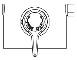
- Move the PRIME/SPRAY valve down to the PRIME position.
GENERAL REPAIR AND SERVICE NOTES
The following tools are needed when repairing this sprayer:
Phillips Screwdriver 3/8” Hex Wrench
Needle Nose Pliers 5/16” Hex Wrench
Adjustable Wrench 1/4” Hex Wrench
Rubber Mallet 3/16” Hex Wrench
Flat-blade Screwdriver 5/32” Hex Wrench
5/64” Hex Wrench
- Before repairing any part of the sprayer, read the instructions carefully, including all warnings.
 Attention
Never pull on a wire to disconnect it. Pulling on a wire could loosen the connector from the wire. - Test your repair before regular operation of the sprayer to be sure that the problem is corrected. If the sprayer does not operate properly, review the repair procedure to determine if everything was done correctly. Refer to the Troubleshooting Charts to help identify other possible problems.
- Make certain that the service area is well ventilated in case solvents are used during cleaning. Always wear protective eyewear while servicing. Additional protective equipment may be required depending on the type of cleaning solvent. Always contact the supplier of solvents for recommendations.
- if you have any further questions concerning your Titan Airless Sprayer, call Titan:
Customer Service (U.S.)………………………………. 1-800-526-5362
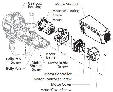
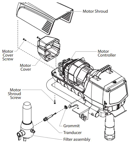
REPLACING THE MOTOR
- Unplug the unit.
- Loosen and remove the two (2) motor shroud screws. Remove the motor shroud.
- Loosen and remove the three (3) belly pan screws. Remove the belly pan.
- Loosen and remove the two (2) motor cover screws. Remove the motor cover.
- Disconnect all wires between the motor and the sprayer.
- Loosen and remove the two (2) motor controller screws. Remove the motor controller.
- Loosen and remove the four (4) motor baffle screws. Remove the motor baffle.
- Loosen and remove the three (3) motor mounting screws.
- Pull the motor out of the gearbox housing.
- With the motor removed, inspect the gears in the gearbox housing for damage or excessive wear. Replace the gears, if necessary.
- Install the new motor into the gearbox housing.
- Secure the motor with the three (3) motor mounting screws.
- Reconnect the wires between the sprayer and the new motor. (refer to the electrical schematic in the Parts List section of this manual).
- Place the baffle over the end of the motor assembly. Secure with the four (4) motor baffle screws.
- Place motor controller back into place behind the motor baffle. Secure with the two (2) motor controller screws.
- Reconnect all wires between the motor and sprayer.
- Place the motor cover back over the motor controller. Secure with the two (2) motor cover screws.
- Put the belly pan back in place and secure with the three (3) belly pan screws.
- Slide the motor shroud over the motor assembly.
- Secure the motor shroud with the two (2) motor shroud screws.

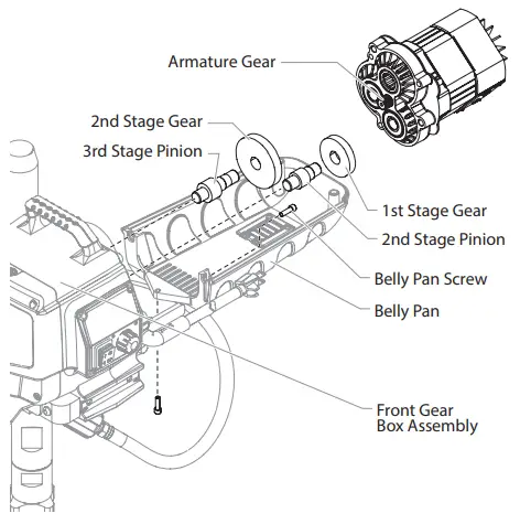
REPLACING THE GEARS
- Follow steps 1-9 in Replacing the Motor Assembly to remove the motor and control panel.
- Inspect the armature gear on the end of the motor for damage or excessive wear. If the gear is completely worn out, replace the motor assembly.
- Remove and inspect the 1st stage gear and 2nd stage gear assemblies for damage or excessive wear. Replace, if necessary.
- Inspect the front gear box assembly for damage or excessive wear. If damaged or worn, replace the front gear box assembly.
 Clean and refill the gear box cavity up to the rear face of each gear with Lubriplate (P/N 314-171).
 - Reinstall the motor into the gearbox housing.
- Follow steps 11-20 in Replacing the Motor Assembly to replace the motor and control panel.

REPLACING THE TRANSDUCER
- Unplug the unit.
- Loosen and remove the two (2) filter assembly bolts. Slide the filter assembly from the cart.
- Loosen and remove the two (2) motor shroud screws. Remove the motor shroud.
- Loosen and remove the two (2) motor cover screws. Remove the motor cover.

- Disconnect the transducer wire from the motor controller.
- Pull the grommet out of the mounting plate and slide it up the shaft of the transducer until it is clear of the mounting plate.
- Using a wrench, loosen and remove the transducer from the filter housing. Carefully thread the transducer wire out through the mounting plate.
- Slide the grommet off of the old transducer and onto the new transducer.
- Thread the new transducer wire through the mounting plate and back to the motor controller.
- Thread the new transducer into the filter housing and tighten securely with a wrench. Make sure the o-ring on the transducer is in place before threading the transducer into the filter housing.
- Push the grommet into the mounting plate.
- Connect the transducer wire to the motor controller (refer to the electrical schematic in the Parts List section of this manual).
- Place the motor cover back over the motor controller. Secure with the two (2) motor cover screws.
- Slide the motor shroud over the motor assembly.
- Secure the motor shroud with the two (2) motor shroud screws.

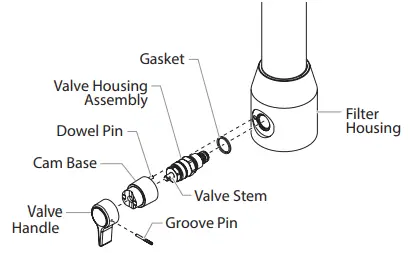
REPLACING THE PRIME/SPRAY VALVE
Perform the following procedure using PRIME/SPRAY valve replacement kit P/N 700-248.
- Push the groove pin out of the valve handle.
- Remove the valve handle and the cam base.
- Using a wrench, loosen and remove the valve housing assembly.
- Make sure the gasket is in place and thread the new valve housing assembly into the filter block. Tighten securely with a wrench.
- Place the cam base over the valve housing assembly. Lubricate the cam base with grease and line up the cam with the filter block using the dowel pin.
- Line up the hole on the valve stem with the hole in the valve handle.
- Insert the groove pin into the valve handle and through the valve stem to secure the valve handle in position.
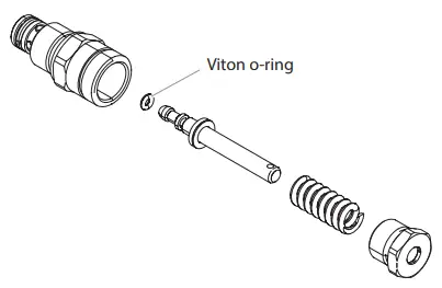
 When using “HOT” solvents, replace Viton o-ring with optional PTFE o-ring (700-897). Install with o-ring tool (700-890).
SERVICING THE FLUID SECTION
Use the following procedures to service the valves and repack the fluid section. Perform the following steps before performing any maintenance on the fluid section.
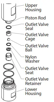
- Loosen and remove the foot valve housing from the lower housing.
- Clean out any debris in the foot valve housing and examine the housing and the foot valve seat. If the seat is damaged, reverse or replace the seat.
- Using two wrenches, hold the upper housing at the wrench flats with one wrench and loosen the lower housing with the other. Remove the lower housing.
- Using a 3/8” hex wrench, loosen and remove the outlet valve retainer from the piston rod. Before proceeding, follow the Pressure Relief Procedure outlined previously in this manual.
Additionally, follow all other warnings to reduce the risk of an injection injury, injury from moving parts or electric shock. Always unplug the sprayer before servicing! - Clean out any debris and examine the retainer and outlet valve seat. If the seat is damaged, reverse or replace the seat.
- Remove, clean, and inspect the outlet valve cage and outlet valve ball. Replace if they are worn or damaged.
- Reassemble the valves by reversing the steps above.
SERVICING THE VALVES
The design of the fluid section allows access to the foot valve and seat as well as the outlet valve and seat without completely disassembling the fluid section. It is possible that the valves may not seat properly because of debris stuck in the foot valve seat or outlet valve seat.
Use the following instructions to clean the valves and reverse or replace the seats.
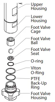
- Loosen and remove the foot valve housing from the lower housing.
- Clean out any debris in the foot valve housing and examine the housing and the foot valve seat. If the seat is damaged, reverse or replace the seat.
- Using two wrenches, hold the upper housing at the wrench flats with one wrench and loosen the lower housing with the other. Remove the lower housing.
- Using a 3/8” wrench, loosen and remove the outlet valve retainer from the piston rod. Always service the outlet valve with the piston rod attached to the pump.
This will prevent the piston rod from rotating during disassembly of the outlet valve.
- Clean out any debris and examine the retainer and outlet valve seat. If the seat is damaged, reverse or replace the seat.
- Remove, clean, and inspect the outlet valve cage and outlet valve ball.
Replace if they are worn or damaged. - Reassemble the valves by reversing the steps above. During reassembly, make sure the Viton o-rings and the PTFE back-up rings between the upper housing and lower housing as well as between the lower housing and the foot valve housing are lubricated with grease and in position.
REPACKING THE FLUID SECTION
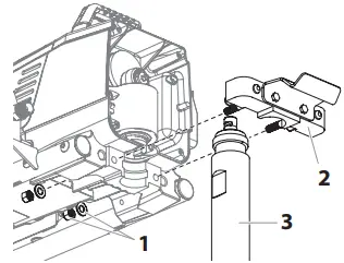
- Remove the foot valve assembly and the lower housing using the steps in the “Servicing the Valves” procedure above. The outlet valve does not need to be disassembled from the piston rod for this procedure.
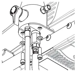
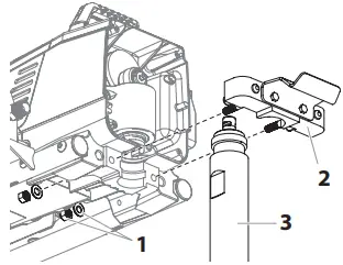
- Loosen and remove the two nuts and washers (1) from underneath the sprayer. Remove the fluid section retainer (2). This will unclamp the entire fluid section (3).

- Slide the fluid section forward to remove it from the gear housing.
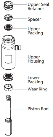
- Place the upper housing upright in a vise by clamping on the wrench flats. Do not over-tighten the vise. Damage to the upper housing may occur.

- Using a wrench, remove the upper seal retainer.
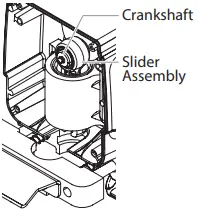
- Slide the piston rod forward until the piston is out of the T-slot on the slider assembly.
- Pull the piston out through the bottom of the upper housing.
- Inspect the piston rod for wear and replace if necessary.
- Remove the upper and lower packings from the upper housing. Be careful not to scratch, score, or otherwise damage the upper
housing during removal of the packings.
- Clean the upper housing. Inspect the upper housing for damage and replace if necessary.
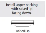
- Locate the new upper and lower packings and pack the areas between the packing lips with grease. Lubricate the o-rings on the exterior of the packings with grease.
- Insert the upper packing into the top of the upper housing with the raised lip on the packing facing down.

- Insert the spacer on top of the upper packing.
- Thread the upper seal retainer into the upper housing and torque to 25-30 ft. lbs.
- Pre-form the lower packing using the lower packing sizing tool (included in the repacking kit).
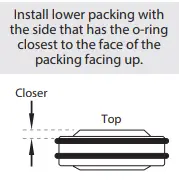
- Insert the lower packing partially into the bottom of the upper housing so that the side that has the o-ring closest to the face of the packing faces up.

- Push the lower packing into position using the lower packing insertion tool (see Fluid Section Assembly parts list for lower packing insertion tool P/N).
- Place the piston insertion tool (included in the repacking kit) over the top of the piston rod.
- Insert the piston rod into the bottom of the upper housing, through the lower packing, through the upper packing, and out through the upper seal retainer. When repacking the fluid section, make sure the raised lip on the bottom of the lower packing is fully outside the packing around the piston rod after insertion of the piston rod.
- Remove the piston insertion tool from the top of the piston rod.
- Replace the upper housing back into the fluid section clamp on the gear housing. Make sure to slide the top of the piston rod into the T-slot on the slider assembly.
- Place the fluid section block back into position over the fluid section. Replace the washers and nuts that secure the fluid section block to the gear housing. Tighten the nuts (torque to 100-130 in-lbs).
- Making sure that the Viton o-ring and PTFE back-up ring are lubricated and in place, thread the lower housing into the upper housing. Using two wrenches, hold the upper housing at the wrench flats with one wrench and tighten the lower housing with the other.
- Attach the high-pressure hose to the nipple on the back of the housing and tighten with a wrench. Do not kink the hose. Make sure the hose does not touch the cart frame. If it does, reposition the nipple by turning the upper housing until the hose is clear of the frame and the nipple is within 45º of the back of the unit.
- Making sure that the Viton o-ring and PTFE back-up ring are lubricated and in place, reassemble the foot valve assembly and and thread it into the lower housing. Tighten securely.
- Thread the siphon tube/siphon set into the foot valve and tighten securely. Make sure to wrap the threads on the down tube/siphon tube adapter with PTFE tape before assembly.
- Replace the return hose into the clamp on the siphon tube.
- Place the front cover on the gearbox housing and secure in position using the four front cover screws.
- Turn on the sprayer by following the procedure in the “Operation” section of this manual and check for leaks. Repacking kit P/N 0558740 is available. For best results use all parts supplied in this kit.
REPLACING THE COMPLETE FLUID SECTION ASSEMBLY
The fluid section for this pump has been designed to be easily replaced by another entire fluid section assembly for on-site replacement.
Follow the steps below.
- Loosen and remove the two nuts and washers (1) from underneath the sprayer. Remove the fluid section retainer (2).
This will unclamp the entire fluid section (3).
- Slide the fluid section forward to remove it from the gear housing.
- Replace the new fluid section back into the the fluid section clamp on the gear housing. Make sure to slide the top of the piston rod into the T-slot on the slider assembly.
- Place the fluid section block back into position over the fluid section. Replace the washers and nuts that secure the fluid section block to the gear housing. Tighten the nuts (torque to 100-130 in-lbs).
REPLACING THE FILTERS
PUMP FILTER
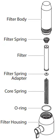
- Loosen and remove the filter body by hand.
- Slip the filter off of the core spring.
- Inspect the filter. Based on inspection, clean or replace the filter.
- Inspect the o-ring. Based on inspection, clean or replace the o-ring.
- Slide the new or cleaned filter over the core spring with the filter spring adapter in place. Push the filter into the center of the filter housing.
- Slide the filter body over the filter and thread it into the filter housing until secure. The filter housing should be handtightened, but make sure the filter housing is seated fully into the pump block.
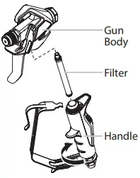
GUN FILTER
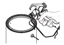
- Unclip the top of the trigger guard from the gun body.
- Using the bottom of the trigger guard as a wrench, loosen and remove the handle assembly from the gun head.
- Pull the old filter out of the gun body. Clean or replace.
- Slide the new filter, tapered end first, into the gun head.
- Thread the handle assembly into the gun head. Tighten with the trigger wrench.
- Snap the trigger guard back onto the gun body.
 For more detail, part number information, and complete assembly drawings, please see the RXPro Airless Gun Owner’s Manual.
TROUBLESHOOTING
| Problem | Cause | Solution |
| A. The unit will not run. | 1. The unit is not plugged in. 2. Tripped breaker. 3. The pressure is set too low (pressure control knob set at minimum setting does not supply power to unit). 4. Faulty or loose wiring. 5. Excessive motor temperature. 6. ON/OFF switch is defective. | 1. Plug the unit in. 2. Reset the breaker. 3. Turn the pressure control knob clockwise to supply power to the unit and increase the pressure setting. 4. Inspect or take to a Titan authorized service center. 5. Allow motor to cool. 6. Replace the ON/OFF switch. |
| B. The unit will not prime. | 1. Inlet valve is stuck. 2. The PRIME/SPRAY valve is in the SPRAY position. 3. Air leak in the siphon tube/suction set. 4. The pump filter and/or inlet screen is clogged. 5. The siphon tube/suction set is clogged. | 1. Insert pusher stem. 2. Rotate the PRIME/SPRAY valve clockwise to the PRIME position. 3. Check the siphon tube/suction set connection and tighten or re-tape the connection with PTFE tape. 4. Remove the pump filter element and clean. Remove the inlet screen and clean. 5. Remove the siphon tube/suction set and clean. |
| C. The unit will not build or maintain pressure. | 1. The spray tip is worn. 2. The spray tip is too large. 3. The pressure control knob is not set properly. 4. The pump filter, gun filter, or inlet screen is clogged. 5. Material flows from the return hose when the PRIME/SPRAY valve is in the SPRAY position. 6. Air leak in the siphon tube/suction set. 7. There is external fluid leak. 8. There is an internal fluid section leak (packings are worn and/or dirty, valve balls are worn). 9. Worn valve seats 10. Motor powers but fails to rotate | 1. Replace the spray tip following the instructions that came with the spray gun. 2. Replace the spray tip with a tip that has a smaller orifice following the instructions that came with the spray gun. 3. Turn the pressure control knob clockwise to increase the pressure setting. 4. Remove the pump filter element and clean. Remove the gun filter and clean. Remove the inlet screen and clean. 5. Clean or replace the PRIME/SPRAY valve. 6. Check the siphon tube/suction set connection and tighten or re-tape the connection with PTFE tape. 7. Check for external leaks at all connections. Tighten connections, if necessary. 8. Clean the valves and service the fluid section following the “Servicing the Fluid Section” procedure in the Maintenance section of this manual. 9. Reverse or replace the valve seats following the “Servicing the Fluid Section” procedure in the Maintenance section of this manual. 10. Take unit to a Titan authorized service center
|
| D. Fluid leakage at the upper end of the fluid section. | 1. The upper packing is worn. 2. The piston rod is worn. | 1. Repack the pump following the “Servicing the Fluid Section” procedure in the Maintenance section of this manual. 2. Replace the piston rod following the “Servicing the Fluid Section” procedure in the Maintenance section of this manual. |
| E. Excessive surge at the spray gun. | 1. Wrong type of airless spray hose. 2. The spray tip worn or too large. 3. Excessive pressure. | 1. Replace hose with a minimum of 50’ of 1/4” grounded textile braid airless paint spray hose. 2. Replace the spray tip following the instructions that came with the spray gun. 3. Rotate the pressure control knob counterclockwise to decrease spray pressure. |
| F. Poor spray pattern. | 1. The spray tip is too large for the material being used. 2. Incorrect pressure setting. 3. Insufficient fluid delivery. 4. The material being sprayed is too viscous. | 1. Replace the spray tip with a new or smaller spray tip following the instructions that came with the spray gun. 2. Rotate the pressure control knob to adjust the pressure for a proper spray pattern. 3. Clean all screens and filters. 4. Add solvent to the material according to the manufacturer’s recommendations. |
| G. The unit lacks power. | 1. The pressure adjustment is too low. 2. Improper voltage supply. | 1. Rotate the pressure control knob clockwise to increase the pressure setting. 2. Reconnect the input voltage for 120V AC. |
SPARE PARTS DIAGRAM
MAIN ASSEMBLY
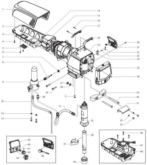
| # | IMPACT 1040 | Description | Qty. |
| 1 | 805-425 | Motor shroud | 1 |
| 2 | 700-681 | Belly pan screw | 3 |
| 3 | 0552404A | Belly pan assembly | 1 |
| 4 | 9802266 | Motor shroud screw | 2 |
| 5 | 805-490 | Belly pan cover | 1 |
| 6 | 700-139 | Belly pan cover screw | 2 |
| 7 | 805-439 | Grommet | 1 |
| 8 | 800-437 | Transducer assembly | 1 |
| 9 | 805-269A | Filter assembly (see separate listing) | 1 |
| 10 | 0558369 | Return tube | 1 |
| 11 | 0552585 | Hose | 1 |
| 12 | 860-002 | Washer | 2 |
| 13 | 9805311 | Screw | 2 |
| 14 | 9802266 | Screw | 2 |
| 15 | 805-462 | Motor controller cover | 1 |
| 16 | 9805317 | Handle screw | 2 |
| 17 | 805-332 | Handle cover, back | 1 |
| 18 | 805-333 | Handle cover, front | 1 |
| 19 | ——- | Drive assembly (see separate listing) | 1 |
| 20 | 700-139 | Control panel screw | 4 |
| 21 | 0552550A | Control panel assembly, complete includes items 39-44) | 1 |
| 22 | 0522404 | Fuse | 1 |
| 23 | 9804916 | Fuse block screw | 1 |
| 24 | 0522210 | Fuse block | 1 |
| 25 | 805-250A | Face plate / oiler assembly | 1 |
| 26 | 700-139 | Face plate screw | 4 |
| 27 | 9812333 | Nut | 2 |
| 28 | 0509285 | Washer | 2 |
| 29 | 805-464 | Retainer | 1 |
| 30 | 9805441 | Bolt | 2 |
| 31 | 805-434 | Pail hook | 1 |
| 32 | 9821503 | Lock washer | 2 |
| 33 | 858-625 | Pail hook screw | 2 |
| 34 | 9805348 | Screw | 4 |
| 35 | 0552603A | Fluid section assembly | 1 |
| 36 | 813-555 | Fitting | 1 |
| 37 | 0523525 | Clip | 1 |
| 38 | 451-241 | Siphon tube | 1 |
| 39 | 0552991 | Control panel cover with label | 1 |
| 40 | 700-176 | Nut with seal | 1 |
| 41 | 704-598 | Set screw | 1 |
| 42 | 805-354 | Control knob | 1 |
| 43 | 9850936 | Switch | 1 |
| 44 | 0508579 | Potentiometer | 1 |
| 45 | 710-046 | Inlet filter | 1 |
| 46 | 9805400 | Screw | 4 |
| 47 | 0552403 | Fan | 1 |
| 48 | 805-428 | Belly pan | 1 |
| 0551972 | Surge suppressor (not shown, see schematic) | 1 | |
| 805-480 | Power cord assembly (not shown) | 1 | |
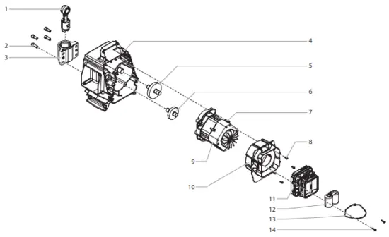
DRIVE ASSEMBLY
![]() All electrical work should be performed by an authorized service center.
All electrical work should be performed by an authorized service center.
| # | IMPACT 1040 | Description | Qty. |
| 1 | 805-241A | Slider assembly | 1 |
| 2 | 700-283 | Screw | 4 |
| 3 | 805-248A | Slider housing | 1 |
| 4 | 805-244A | Housing assembly | 1 |
| 5 | 0558362A | 3rd stage gear | 1 |
| 6 | 0558363A | 2nd stage gear | 1 |
| 7 | 700-681 | Motor mount screw | 3 |
| 8 | 700-139 | Motor baffle screw | 4 |
| 9 | 805-271A | Motor assembly | 1 |
| 10 | 805-460 | Motor baffle | 1 |
| 11 | 0552990 | Motor controller | 1 |
| 12 | 0522027 | Capacitor assembly | 1 |
| 13 | 770-099 | Tie wrap | 1 |
| 14 | 9802266 | Motor controller screw | 2 |
CART ASSEMBLY
(P/N 0552591A)
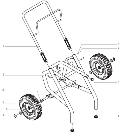
| # | IMPACT 1040 | Description | Qty. |
| 1 | 805-206A | Handle assembly | 1 |
| 2 | 0552592A | Cart weldment | 1 |
| 3 | 856-002 | Washer | 4 |
| 4 | 856-921 | Screw | 4 |
| 5 | 0295687 | Wheel spacer | 4 |
| 6 | 670-109 | Wheel | 2 |
| 7 | 800-019 | Axle cap | 2 |
| 8 | 0294635 | Plug | 2 |
| 9 | 9885571 | Plug | 2 |
FLUID SECTION
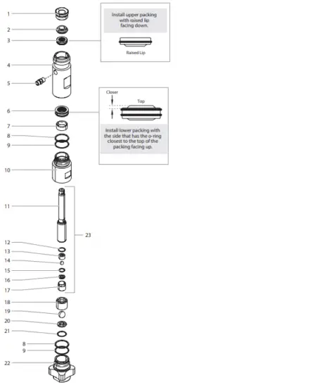
| # | IMPACT 1040 | Description | Qty. |
| 1 | 805-545 | Seal retainer | 1 |
| 2 | 805-544 | Spacer | 1 |
| 3 | 800-353A | Upper packing assembly | 1 |
| 4 | 805-450 | Upper housing | 1 |
| 5 | 0508343 | Fitting | 1 |
| 6 | 800-355A | Lower packing assembly | 1 |
| 7 | 800-354 | Wear ring | 1 |
| 8 | 800-332 | O-ring, Viton | 2 |
| 9 | 800-333 | O-ring, PTFE | 2 |
| 10 | 800-352 | Lower housing | 1 |
| 11 | 805-456A | Piston rod | 1 |
| 12 | 800-348 | Outlet valve seal | 1 |
| 13 | 0507452 | Upper cage | 1 |
| 14 | 9841502 | Outlet valve ball | 1 |
| 15 | 0507454 | Washer | 1 |
| 16 | 0294516 | Outlet valve seat | 1 |
| 17 | 800-336 | Outlet valve retainer | 1 |
| 18 | 800-322 | Lower cage | 1 |
| 19 | 51519 | Inlet ball | 1 |
| 20 | 00310 | Inlet seat | 1 |
| 21 | 9871218 | O-ring | 1 |
| 22 | 800-305 | Foot valve | 1 |
| 23 | 805-247A | Piston assembly (includes items 11-17) | 1 |
| 0558740 | Repacking kit (includes items 2-3, 6-9, 12, 14, 15, 19 and 21) | ||
| 800-359 | Piston insertion tool |
FILTER ASSEMBLY
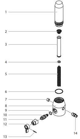
| # | IMPACT 1040 | Description | Qty. |
| 1 | 800-905 | Filter body | 1 |
| 2 | 14058 | Filter spring | 1 |
| 3 | 730-067 | Filter assembly | 1 |
| 4 | 702-251 | Adapter | 1 |
| 5 | 757-105 | Spring | 1 |
| 6 | 800-906 | O-ring | 1 |
| 7 | 800-908 | Plug | 1 |
| 8 | 805-508 | Filter housing | 1 |
| 9 | 700-537 | Gasket | 1 |
| 10 | 800-925 | Bypass valve assembly | 1 |
| 11 | 700-252 | Cam base | 1 |
| 12 | 700-697 | Valve handle | 1 |
| 13 | 700-759 | Groove pin | 1 |
| 14 | 812-003 | Fitting | 1 |
| 700-258 | Bypass valve assembly, complete (includes items 9-13) |
LABELS
| Part No. | Description |
| 805-810 | Front cover label |
| 0552597 | Motor cover label (1040) |
| 805-818 | Warning label |
| 0552878 | Pressure control panel label |
ELECTRICAL SCHEMATIC
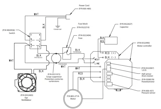
![]() All electrical work should be performed by an authorized service center.
All electrical work should be performed by an authorized service center.
ACCESSORIES
| # | Description |
| Spray Guns | |
| 0538020 | 2 Finger RX-Pro with TR-1 Tip |
| 0538022 | 2 Finger RX-Pro with TR-1 Tip and hose |
| Spray tips and accessories | |
| 662-XXX | SC-6+ Tip* |
| 695-XXX | TR-1 Tip* |
| 692-XXX | TR-2 Tip* |
| 671-XXX | Fine Finish Tip* |
| 0289228 | No Build Tip Guard |
| 651-139 | Tip Swivel |
| 661-020 | Tip seat and seal kit (5 pack) |
| Filters | |
| 0089957 | Coarse Mesh Filter (Green) |
| 0089958 | Medium Mesh Filter (White) |
| 0089959 | Fine Mesh Filter (Yellow) |
| 0089960 | Extra Fine Mesh Filter (Red) |
| Extensions | |
| 651-070 | 6″ Tip Extension |
| 651-071 | 12″ Tip Extension |
| 651-072 | 18″ Tip Extension |
| 651-073 | 24″ Tip Extension |
| 310-390 | 3′ Extension Pole |
| 310-391 | 6′ Extension Pole |
| Airless hose and accessories | |
| 316-505 | 1/4″ x 50′ Airless Hose |
| 316-506 | 3/16″ x 5′ Whip Hose |
| 490-012 | 1/4″ x 1/4″ hose connector |
| 0508239 | High Pressure Fluid Gauge |
| 310-150 | 9” Pressure Roller Kit |
| 0538900 | Spray Guide Kit |
| Lubricants and cleaners | |
| 314-482 | Liquid Shield™ 1 Quart |
| 314-480 | Piston Lube™, 8 oz |
| 700-926 | Piston Lube™, 1 Quart |
| 0297055 | Pump Shield™ |
| 0508071 | Paint Mate 1 quart |
| Service kits (optional) | |
| 0558740 | Repacking kit |
| 800-359 | Piston insertion tool |
Go to www.titantool.com for tip sizes
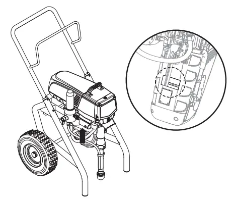
SERIAL NUMBER LOCATION
PRODUCT REGISTRATION
Register your product online at www.titantool.com.
WARRANTY
Titan Tool, Inc., (“Titan”) warrants that at the time of delivery to the original purchaser for use (“End User”), the equipment covered by this warranty is free from defects in material and workmanship. With the exception of any special, limited, or extended warranty published by Titan, Titan’s obligation under this warranty is limited to replacing or repairing without charge those parts which, to Titan’s reasonable satisfaction, are shown to be defective within twelve (12) months after sale to the End User. This warranty applies only when the unit is installed and operated in accordance with the recommendations and instructions of Titan.
This warranty does not apply in the case of damage or wear caused by abrasion, corrosion or misuse, negligence, accident, faulty installation, substitution of non-Titan component parts, or tampering with the unit in a manner to impair normal operation.
Defective parts are to be returned to an authorized Titan sales/service outlet. All transportation charges, including return to the factory, if necessary, are to be borne and prepaid by the End User. Repaired or replaced equipment will be returned to the End User transportation prepaid.
THERE IS NO OTHER EXPRESS WARRANTY. TITAN HEREBY DISCLAIMS ANY AND ALL IMPLIED WARRANTIES INCLUDING, BUT NOT LIMITED TO, THOSE OF MERCHANTABILITY AND FITNESS FOR A PARTICULAR PURPOSE, TO THE EXTENT PERMITTED BY LAW. THE DURATION OF ANY IMPLIED WARRANTIES WHICH CANNOT BE DISCLAIMED IS LIMITED TO THE TIME PERIOD SPECIFIED IN THE EXPRESS WARRANTY. IN NO CASE SHALL TITAN LIABILITY EXCEED THE AMOUNT OF THE PURCHASE PRICE. LIABILITY FOR CONSEQUENTIAL, INCIDENTAL OR SPECIAL DAMAGES UNDER ANY AND ALL WARRANTIES IS EXCLUDED TO THE EXTENT PERMITTED BY LAW.
TITAN MAKES NO WARRANTY AND DISCLAIMS ALL IMPLIED WARRANTIES OF MERCHANTABILITY AND FITNESS FOR A PARTICULAR PURPOSE WITH RESPECT TO ACCESSORIES, EQUIPMENT, MATERIALS OR COMPONENTS SOLD BUT NOT MANUFACTURED BY TITAN. THOSE ITEMS SOLD, BUT NOT MANUFACTURED BY TITAN (SUCH AS GAS ENGINES, SWITCHES, HOSES, ETC.) ARE SUBJECT TO THE WARRANTY, IF ANY, OF THEIR MANUFACTURER. TITAN WILL PROVIDE THE PURCHASER WITH REASONABLE ASSISTANCE IN MAKING ANY CLAIM FOR BREACH OF THESE WARRANTIES.
UNITED STATES SALES & SERVICE
WEB: www.titantool.com
PHONE: 1-800-526-5362
1770 Fernbrook Lane
Minneapolis, MN 55447
INTERNATIONAL
EMAIL: [email protected]


