SKYJACKER 2011-2023 GM 2500 HD 3500 HD Component Box Instruction Manual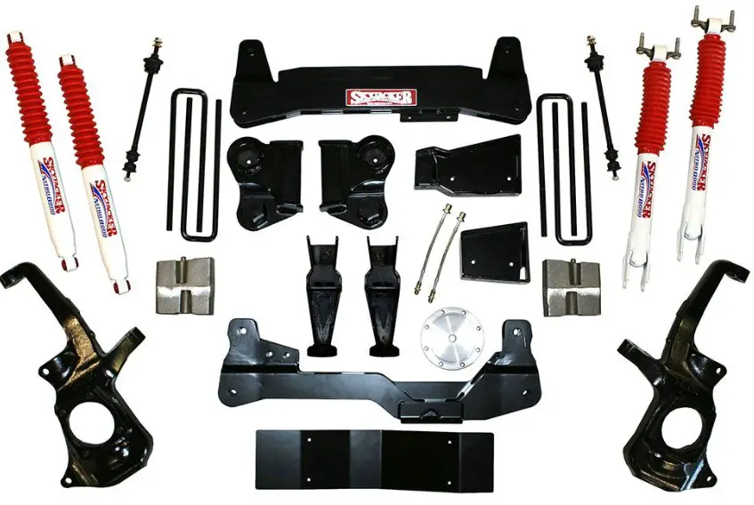
Required Tools List
- SAE Hex Key & SAE Sockets \ Wrenches (5/32″ Hex Key Socket & 15/16″)
- Metric Hex Key & Metric Sockets \ Wrenches (15mm, 18mm, 19mm, 21mm, 22mm & 24mm)
- Torsion Bar Puller Tool
- Ball Peen Hammer
- Grease Gun
- Safety Glasses
- Floor Jack
- Paint Marker
- Measuring Tape
- Punch
- Bench Vise
- Wheel Chock
- Jack Stands
- Torque Wrench
Before beginning installation, read these instructions & enclosed driver’s WARNING NOTICE thoroughly & completely. Also affix WARNING decal in passenger compartment in clear view of all occupants. Please refer to Parts List to insure that all parts & hardware are received prior to disassembly of vehicle. If any parts are found to be missing, contact SKYJACKER® Customer Service at 318-388-0816 to obtain needed items. If you have any questions or reservations about installing this product, contact SKYJACKER® Technical Assistance at 318-388-0816.
Make sure you park vehicle on a level concrete or asphalt surface. Many times a vehicle is not level (side-to-side) from factory, but is usually not noticed until a lift kit has been installed which makes difference more visible. Using a measuring tape, measure front & rear (both sides) from ground up to center of fender opening above axle. Record this information below for future reference.
Driver Side Front: __________ Passenger Side Front: _______
BEFORE / AFTER BEFORE / AFTER
Driver Side Rear: __________ Passenger Side Rear: _________
BEFORE / AFTER BEFORE / AFTER
Important Notes
- This Suspension Lift is NOT Designed to Fit the Following Models:
- Chevrolet or GMC Models With Magnetic Ride Control
- Models With Top Mount Rear Overload Springs. Note: Models with Top Mount Rear Overload Springs MUST Also Order Skyjacker Part # UDB6R Rear U-Bolt Kit.
- If Larger Tires (10% More Than the OEM Diameter) Are Installed, Speedometer Recalibration Will Be Necessary. Contact Your Local GM Dealer or an Authorized Skyjacker® Dealer for Details.
- After Installation, a Qualified Alignment Facility Is Required to Align the Vehicle to the OEM Specifications.
- A Torsion Bar Puller Tool Is Required for the Safe Removal \ Installation of the OEM Torsion Bars. A Torsion Bar Puller Tool Can Be Purchased from a GM Dealer or Most Auto Parts Stores (a Rental Option May Be Available).
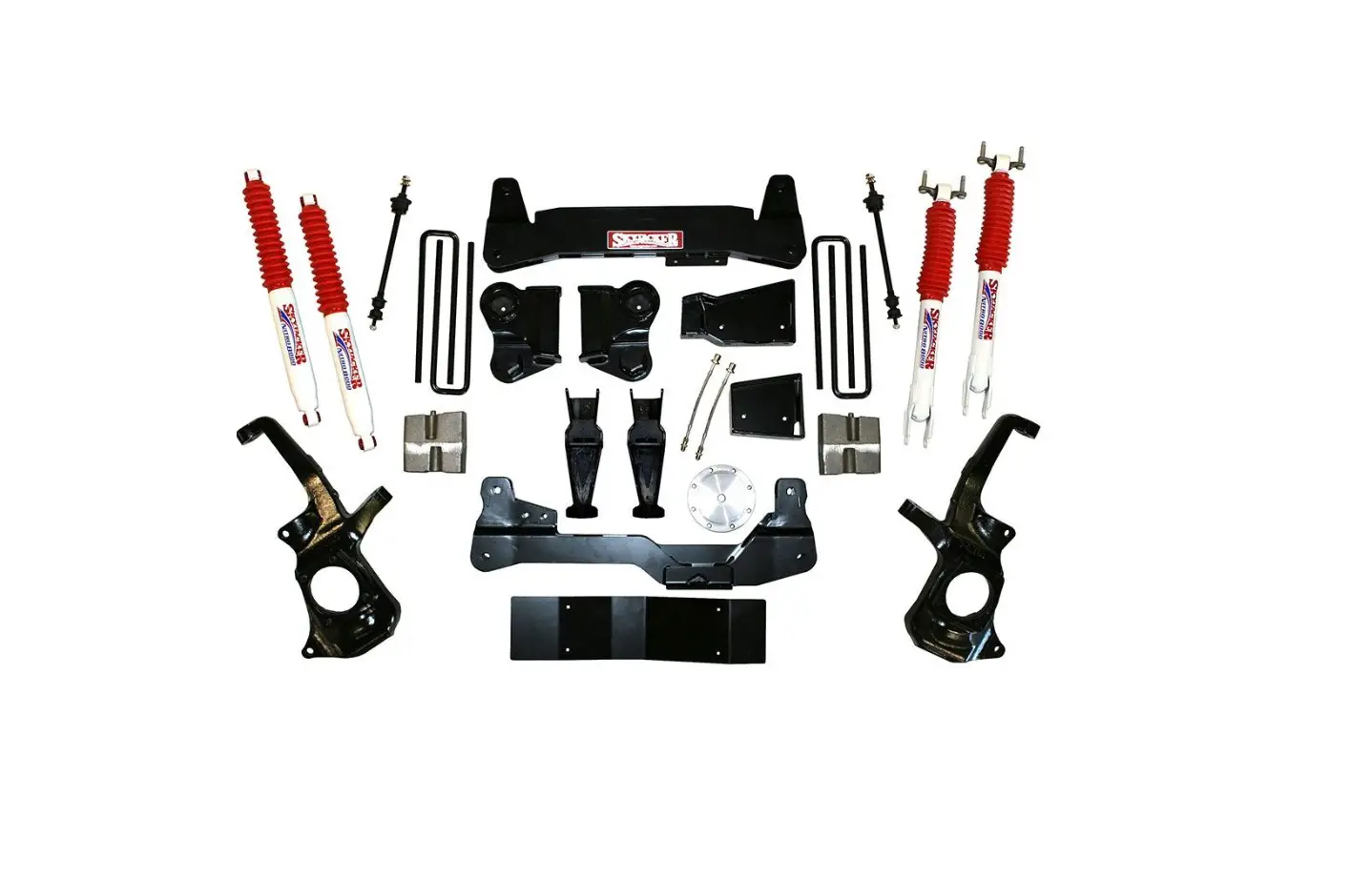
Component Box Breakdown:
Part # C11350
| Item # | Description | Qty |
| GM1123UCA-L | UPPER CONTROL ARM, DR | 1 |
| GM1123UCA-R | UPPER CONTROL ARM, PA | 1 |
| H-BOX C11350P | HDWR BOX: C11350P KIT | 1 |
Part # C11350PB
| Item # | Description | Qty |
| GM1123UCA-L | UPPER CONTROL ARM, DR | 1 |
| GM1123UCA-R | UPPER CONTROL ARM, PA | 1 |
| H-BOX C11350P | HDWR BOX: C11350P KIT | 1 |
| B8517 (REAR) | BLACK MAX SHOCK W/BLK BOOT | 2 |
Part # C11350PH
| Item # | Description | Qty |
| GM1123UCA-L | UPPER CONTROL ARM, DR | 1 |
| GM1123UCA-R | UPPER CONTROL ARM, PA | 1 |
| H-BOX C11350P | HDWR BOX: C11350P KIT | 1 |
| H7017 (REAR) | HYDRO SHOCK W/RED BOOT | 2 |
Part # C11350PM
| Item # | Description | Qty |
| GM1123UCA-L | UPPER CONTROL ARM, DR | 1 |
| GM1123UCA-R | UPPER CONTROL ARM, PA | 1 |
| H-BOX C11350P | HDWR BOX: C11350P KIT | 1 |
| M9517 (REAR) | M95 MONOTUBE SHOCK | 2 |
Part # C11350PN
| Item # | Description | Qty |
| GM1123UCA-L | UPPER CONTROL ARM, DR | 1 |
| GM1123UCA-R | UPPER CONTROL ARM, PA | 1 |
| H-BOX C11350P | HDWR BOX: C11350P KIT | 1 |
| N8017 (REAR) | NITRO SHOCK W/RED BOOT | 2 |
Component Box Breakdown
Part # C20350
| Item # | Description | Qty |
| GM2023UCA-L | UPPER CONTROL ARM, DR | 1 |
| GM2023UCA-R | UPPER CONTROL ARM, PA | 1 |
| H-BOX C20350P | HDWR BOX: C20350P KIT | 1 |
Part # C20350PB
| Item # | Description | Qty |
| GM2023UCA-L | UPPER CONTROL ARM, DR | 1 |
| GM2023UCA-R | UPPER CONTROL ARM, PA | 1 |
| H-BOX C20350P | HDWR BOX: C20350P KIT | 1 |
| B8517 (REAR) | BLACK MAX SHOCK W/BLK BOOT | 2 |
Part # C20350PH
| Item # | Description | Qty |
| GM2023UCA-L | UPPER CONTROL ARM, DR | 1 |
| GM2023UCA-R | UPPER CONTROL ARM, PA | 1 |
| H-BOX C20350P | HDWR BOX: C20350P KIT | 1 |
| H7017 (REAR) | HYDRO SHOCK W/RED BOOT | 2 |
Part # C20350PM
| Item # | Description | Qty |
| GM2023UCA-L | UPPER CONTROL ARM, DR | 1 |
| GM2023UCA-R | UPPER CONTROL ARM, PA | 1 |
| H-BOX C20350P | HDWR BOX: C20350P KIT | 1 |
| M9517 (REAR) | M95 MONOTUBE SHOCK | 2 |
Part # C20350PN
| Item # | Description | Qty |
| GM2023UCA-L | UPPER CONTROL ARM, DR | 1 |
| GM2023UCA-R | UPPER CONTROL ARM, PA | 1 |
| H-BOX C20350P | HDWR BOX: C20350P KIT | 1 |
| N8017 (REAR) | NITRO SHOCK W/RED BOOT | 2 |
Hardware Box Breakdown
Part # H-BOX C11350P
| Item # | Description | Qty |
| C115KE-S | TORSION KEY | 2 |
| RB27 | REAR BLOCK | 2 |
| 58X318X1312U | 5/8 X 3-1/8 X 13-1/2 SQ U-BOLT | 4 |
| HB-58 | HDWR BAG: 5/8 N/I LOCK NUT | 1 |
| HB-58SAEW-8 | HDWR BAG: 5/8 SAE WASHERS | 1 |
| HB-GM11DS | HDWR BAG: DIFF SPACERS | 1 |
| HB-GM11SE | HDWR BAG: SHOCK EXT | 1 |
| I-C11350P | INST SHEET: C11350P | 1 |
Part # H-BOX C20350P
| Item # | Description | Qty |
| C205KE-S | TORSION KEY | 2 |
| RB27 | REAR BLOCK | 2 |
| 58X318X1312U | 5/8 X 3-1/8 X 13-1/2 SQ U-BOLT | 4 |
| HB-58 | HDWR BAG: 5/8 N/I LOCK NUT | 1 |
| HB-58SAEW-8 | HDWR BAG: 5/8 SAE WASHERS | 1 |
| HB-GM11DS | HDWR BAG: DIFF SPACERS | 1 |
| HB-GM11SE | HDWR BAG: SHOCK EXT | 1 |
| I-C11350P | INST SHEET: C11350P | 1 |
Part # HB-58
| Item # | Description | Qty |
| 58FTN | 5/8 FINE THREAD N/I LOCK NUT | 8 |
Part # HB-58SAEW-8
| Item # | Description | Qty |
| 58SAEW | 5/8 SAE WASHER | 8 |
Part # HB-GM11DS
| Item # | Description | Qty |
| GM1123DS-S | DIFFERENTIAL SPACER, FRONT | 4 |
| 14X130MMB | 14MM X 130MM METRIC BOLT | 4 |
| 916SAEW | 9/16 SAE WASHER | 8 |
| 14MMN | 14MM METRIC N/I LOCK NUT | 4 |
Part # HB-GM11SE
| Item # | Description | Qty |
| GM11SE-S | SHOCK EXTENSION, FRONT | 2 |
| 12X70MMB | 12MM X 70MM METRIC BOLT | 4 |
| 12SAEW | 1/2 SAE WASHER | 4 |
| 12MMN | 12MM METRIC N/I LOCK NUT | 4 |
Front Installation
Note: Save all factory components & hardware for reuse, unless noted.
- With vehicle on flat level ground, set emergency brake & chock rear tires \ wheels.
- Raise front of vehicle, support frame rails using jack stands at indicated lift points in OEM service manual.
- Remove front tires \ wheels using a 22mm socket.
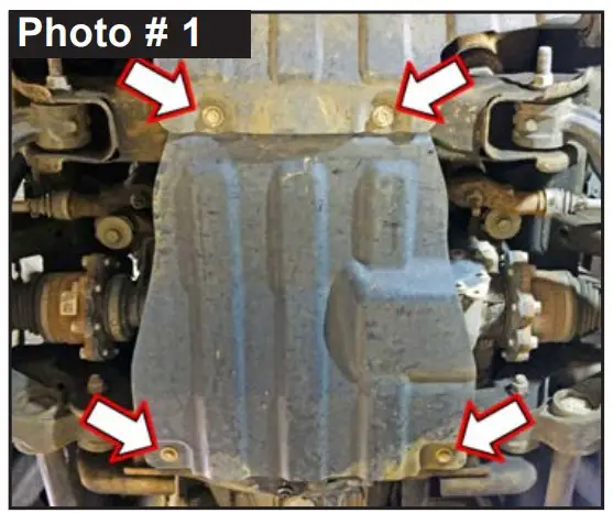
- If equipped, remove four (4) bolts from front OEM skid plate located under front differential using a 15mm socket. (See Photo # 1)

WARNING: Be extremely careful when loading or unloading OEM torsion bars, there is a tremendous amount of stored energy (load pressure) in OEM torsion bars. Keep your hands & body clear of OEM adjuster arm assembly & torsion bar puller tool in case anything slips or breaks.
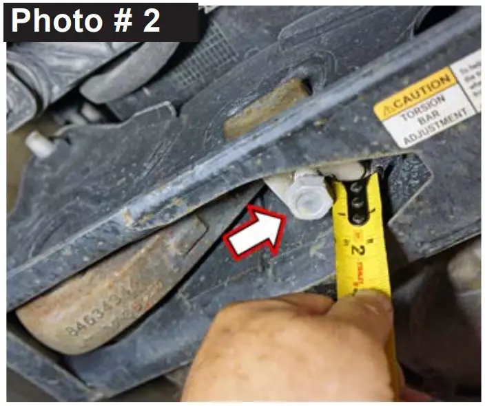
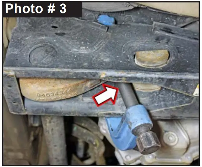
NOTE: Perform Step 5 on One Side at a Time. Complete Steps on Driver Side, THEN Go to Passenger Side & Repeat Same Steps. - Locate OEM torsion bar adjuster bolt on bottom of OEM
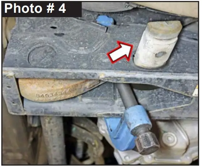
torsion bar crossmember. Measure & record exposed length of OEM torsion bar adjuster bolt. (See Photo # 2) Tech Note: During reassembled, this will be the starting measurement for ride height. Driver Side: ___________ Passenger Side: ___________ Remove OEM torsion bar retainer bolt using a 21mm socket. (See Photo # 3) Apply a small amount of lubricating grease to torsion bar puller threads & torsion bar puller shaft-to-adjuster arm contact point. Position torsion bar puller so torsion bar adjuster block can be removed from crossmember. Load adjuster arm until OEM adjuster bolt & adjuster block can be removed from OEM torsion bar crossmember using a 21mm socket. (See Photo # 4) With OEM torsion bar unloaded, slide OEM torsion bar forward into each OEM lower A-arm. Remove OEM torsion key. (See Photo # 5) Tech Note: If an OEM torsion bar seems lodged, use a hammer & punch through hole in back of the OEM torsion bar crossmember to dislodge. Let torsion bar hang in OEM lower control arm. Do Not Remove from vehicle.

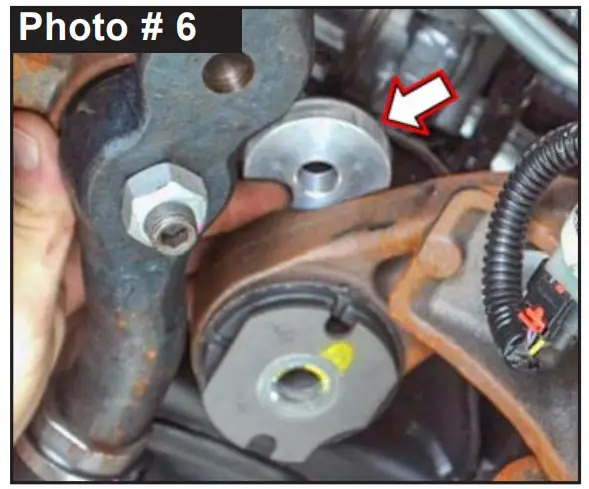
- Place a jack or jack stand under front OEM differential to support weight of differential. Remove two (2) front OEM differential mount bolts using a 21mm socket \ wrench top & bottom. Slightly lower differential. Install Skyjacker # GM1123DS-S Differential Lowering Spacer between front OEM differential mounts & frame. (See Photo # 6) Install with supplied 14mm x 130mm bolt with 9/16″ SAE Washer bottom & with a 9/16″ SAE Washer & 14mm Nylon Insert Lock Nut top using a 22mm socket \ wrench top & bottom.

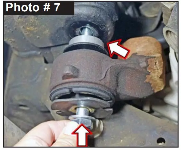
- Remove two (2) rear OEM differential mount bolts using a 21mm socket \ wrench top & bottom. Slightly lower the front differential. Install Skyjacker # GM1123DS-S Differential Lowering Spacers between OEM front differential mounts & frame. (See Photo # 7) Install with supplied 14mm x 130mm bolt with 9/16″ SAE Washer bottom & with a 9/16″ SAE Washer & 14mm Nylon Insert Lock Nut top using a 22mm socket \ wrench top & bottom. Tighten to All Four (4) Differential Mounts. Torque 120 ft-lbs. Remove jack from differential.
- 8. If equipped, install front OEM skid plate using a 15mm socket \ wrench. (See Photo # 1) NOTE: Perform Steps 9-16 on One Side at a Time. Complete Steps 9-16 on One Side, THEN Go to Opposite Side & Repeat Same Steps.
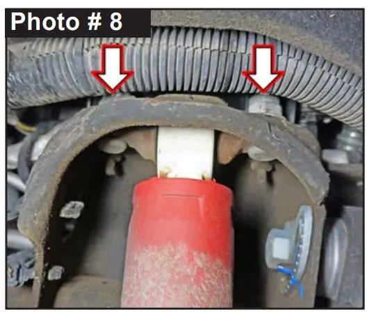
- Support bottom of OEM lower control arm \ steering knuckle with a jack. On driver side, disconnect wiring harness clips from OEM upper shock mounting bolt studs. Remove OEM front shocks using a 21mm socket \ wrench top & bottom. (See Photo # 8)
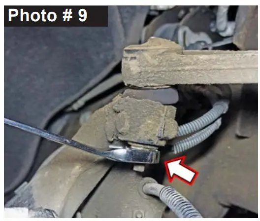
- Loosen, but do not remove upper OEM ball joint nut from OEM knuckle using a 18mm wrench. (See Photo # 9) To unseat upper OEM ball joint taper, strike ball joint boss of knuckle using ball peen hammer to dislodge. Note: ONLY strike knuckle portion only. Remove nut & remove ball joint from knuckle. Tech Note: You may need to pry upper control arm down to disconnect ball joint.
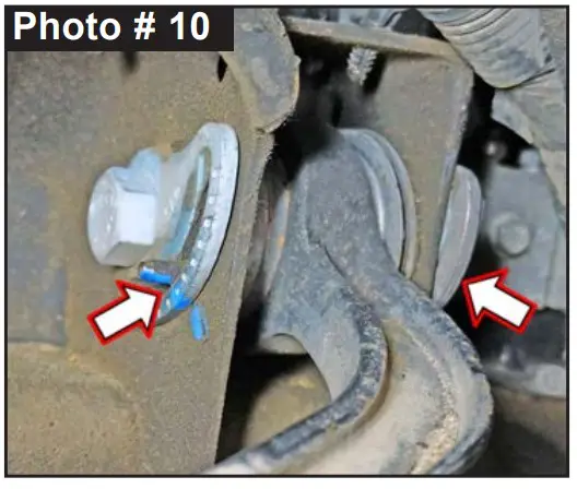
- Mark location of OEM Upper Control Arm (UCA) alignment cams. Remove OEM UCA using a 24mm socket \ wrench each side. (See Photo # 10)

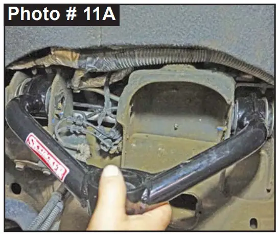
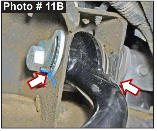
- Note: Skyjacker UCA are Side Specific: Part number is on silver bar code label. Part # ends in -L Driver & -R Passenger. Install Skyjacker UCA to appropriate side of vehicle. Align location of OEM alignment cams with OEM hardware using a 24mm socket \ wrench. (See Photo # 11A & # 11B) Secure, but Do Not Completely Tighten control arm hardware at this time. To set bushings properly for ride height, these will be tightened once vehicle is on ground with full vehicle weight on tires \ wheels.
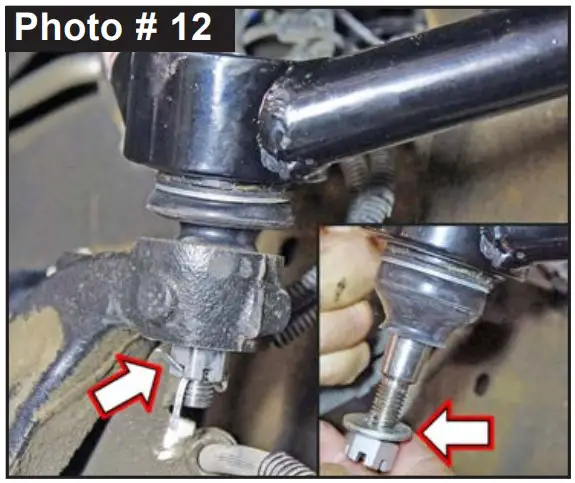
- While supporting OEM lower control arm \ steering knuckle, connect Skyjacker UCA ball joint nut to OEM knuckle with supplied castle nut using a 18mm socket \ wrench. (See Photo # 12) Align cotter pin. CAUTION: Ensure castle nut & cotter pin align properly into Skyjacker UCA ball joint. Never loosen castle nut to align cotter pin; always tighten. Note: On some models, supplied washer may or may not be needed. Check fit with washer to see if the castle nut aligns properly with cotter pin opening. If not, install without washer.
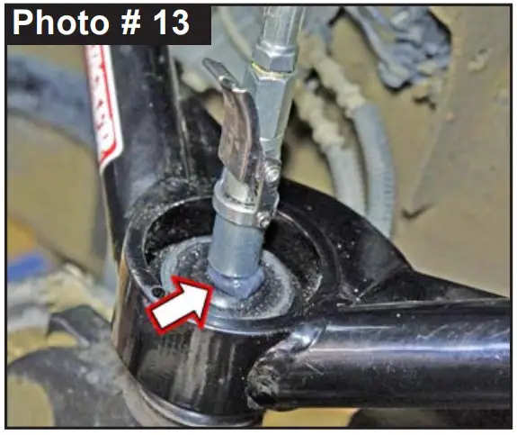
- Grease Skyjacker UCA ball joint using a grease gun. CAUTION: Skyjacker UCA Ball Joint is not fully greased from factory. GREASE Must Be Added to Skyjacker UCA Ball Joint using a grease gun. (See Photo # 13)
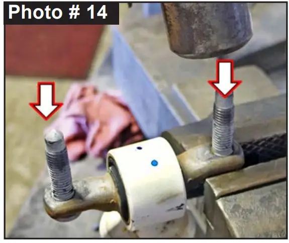
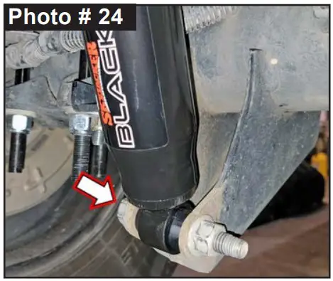
- Remove OEM shock bar pin studs. Place upper bar pin of OEM shock in a vise. Carefully knock out bar pin studs using a ball peen hammer. (See Photo # 14)


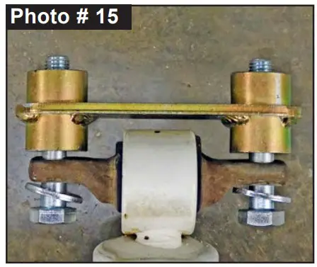
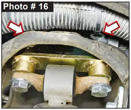
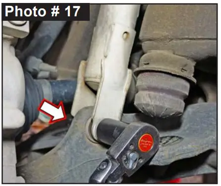
- Locate Skyjacker # GM11SE-S Upper Shock Extension Bracket. Insert supplied 12mm x 70mm bolt with 1/2″ SAE Washer through bar pin mount with as shown. (See Photo # 15) Attach to upper OEM shock mount with supplied 1/2″ SAE Washer & 12mm Nylon Insert Lock Nut using a 19mm socket \ wrench top & bottom. (See Photo # 16) Secure, but Do Not Completely Tighten. Connect OEM shock into lower shock mount with OEM hardware using a 21mm socket \ wrench each side. (See Photo # 17) Secure, but Do Not Completely Tighten. Tighten upper shock mount using a 19mm socket \ wrench top & bottom. Torque 59 ft-lbs. NOTE: Perform Steps 9-16 on Opposite Side of Vehicle at this Time.


WARNING: Be extremely careful when loading or unloading OEM torsion bars.
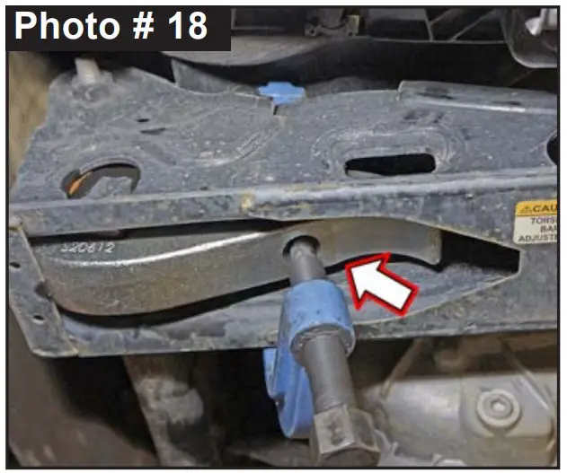
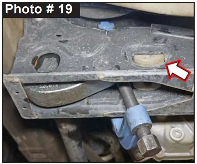
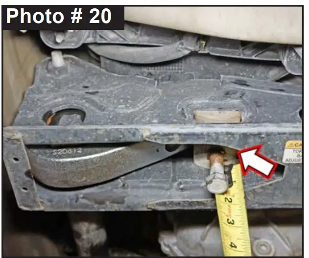
NOTE: Perform Step 17 on One Side at a Time. Complete Steps on Driver Side, THEN Go to Passenger Side & Repeat Same Steps. - Install Skyjacker Torsion Key up into crossmember. Slide torsion bar into hex opening & completely through key. Torsion bar should be locked into position in front lower control arm factory mount. (See Photo # 18) Apply a small amount of lubricating grease to torsion bar puller threads & torsion bar puller shaft-to-adjuster arm contact point. Position torsion bar puller so adjuster block & adjuster bolt can be reinstalled into crossmember. Load adjuster arm until OEM adjuster block can be installed into OEM torsion bar crossmember. (See Photo # 19) Reinstall adjuster block & reinstall adjuster bolt using a 21mm socket. (See Photo # 20) Note: Tighten OEM adjuster bolt to same length as your measurement in Step # 5.

- Install front tires \ wheels using a 22mm socket & lower front of vehicle to ground
Rear Installation
Note: Save all factory components & hardware for reuse, unless noted
- Chock front tires \ wheels. Raise rear of vehicle & support frame rails using jack stands at indicated lift points in OEM service manual.
- Remove rear tires \ wheels using a 22mm socket.
- Disconnect OEM ABS lines from rear differential.
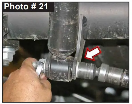
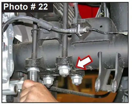
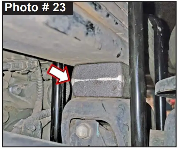
- Support rear differential & remove OEM rear shocks using a 21mm socket \ wrench. (See Photo # 21) 5. Remove OEM u-bolts using a 21mm socket \ wrench. (See Photo # 22) Discard u-bolts & hardware. Retain lower OEM u-bolt plate.


- While checking for appropriate slack in ABS lines, brake lines, rear emergency brake cables, & etc. Lower axle away from leaf springs to allow clearance for block. Clean spring pads of all debris. Position Skyjacker # RB27 2″ Lift Block on top of axle pad. Note: Place taller end of lift block toward rear of vehicle. Raise axle to mate leaf springs to lift blocks. Note: Be sure that leaf spring center bolt head seats properly into block & that block pin seats properly into top of axle pad.
- Install Skyjacker 5/8” U-Bolts over OEM top plate \ leaf springs down into OEM u-bolt plate. Install supplied 5/8″ Nylon Insert Nuts & 5/8″ SAE Washers using a 15/16″ socket \ wrench. Torque u-bolts evenly using an ‘X’ crisscross tightening sequence. Torque 125 ft-lbs. NOTE: Kit With HYDRO, NITRO, Black MAX, or M95 Monotube: Proceed to Step 8. Kit With ADX 2.0 Remote Reservoir: Proceed to Step 9.
- Install Skyjacker rear shock. Connect upper shock mount with OEM hardware using a 21mm socket \ wrench. Connect lower shock mount with OEM hardware using a 21mm socket \ wrench. Secure, but Do Not Completely Tighten at this time. Tighten upper shock mount using a 21mm socket \ wrench. Torque 65 ft-lbs.
- Locate Skyjacker ADX rear shock. Loosely assemble two (2) supplied reservoir clamps with two (2) supplied hex head bolts using a 5/32″ Hex Key socket. Position clamp into place around shock body & reservoir cylinder. Secure, but Do Not Completely Tighten at this time. Install Skyjacker ADX rear shock. Connect upper shock mount with OEM hardware using a 21mm socket \ wrench. Connect lower shock mount with OEM hardware using a 21mm socket \ wrench. Secure, but Do Not Completely Tighten at this time. Tighten upper shock mount using a 21mm socket \ wrench. Torque 65 ft-lbs. CAUTION: Make Sure ADX Shock Reservoir \ Reservoir Hose Does Not & Will Not Make Contact with Anything Throughout the Full Travel Cycle of the Suspension. (frame, frame brackets, springs, brake lines, exhaust, etc.) For proper clearance, it may be necessary to change the location or orientation of the reservoir on the shock body. Use a 5/32″ Hex Key socket to loosen clamps to position reservoir cylinder as needed.
- Connect OEM ABS lines to rear differential. Connect other components that you loosened (ABS lines, brake lines, rear emergency brake cables, & etc). 11. Install rear tires \ wheels using a 22mm socket & lower vehicle to ground.
Final Front Steps:
- Start vehicle. Make sure there are no dash lights pertaining to suspension.
- Jounce vehicle a couple of times. This will help suspension settle to new ride height. Cycle steering lock-to-lock & check all components for proper operation & clearances. Pay special attention to clearance between tires \ wheels, ADX Shocks & Reservoirs, control arms, brake hoses, ABS wiring, etc.
- Realign marks on UCA cam positions. Tighten both Skyjacker UCAs using a 24mm socket \ wrench to set bushings properly for ride height. Torque 250 ft-lbs. Note: Final torque will be set by alignment technician.
- Front Tighten & Torque Sequence. Front shock absorber lower mount using a 21mm socket \ wrench. Torque 65 ft-lbs.
- Rear Tighten & Torque Sequence. Rear shock absorber lower mount using a 21mm socket \ wrench. Torque 65 ft-lbs. ADX Reservoir clamp. Double check position & clearance. Tighten with 5/32″ Hex Key socket.
Final Notes
- After installation is complete, double check that all nuts & bolts are tight. Refer to the following chart for proper torque specifications. (Note: Do not re-tighten nuts & bolts where thread lock compound was used.)
- With vehicle placed on ground, cycle steering lock to lock & inspect steering, suspension, brake lines, front & rear drivelines, fuel lines & wiring harnesses for proper operation, tightness & adequate clearance.
- Have headlights readjusted to proper settings.
- Have a qualified alignment center align vehicle to OEM specifications.
- After first 100 miles, check all hardware for proper torque & periodically thereafter.
TORQUE SPECIFICATIONS
| INCH SYSTEM | METRIC SYSTEM | ||||
| Bolt Size | Grade 5 | Grade 8 | Bolt Size | Class 8.8 | Class 10.9 |
| 5/16 | 180 in-lbs | 240 in-lbs | 6MM | 102 in-lbs | 108 in-lbs |
| 3/8 | 30 ft-lbs | 35 ft-lbs | 8MM | 16 ft-lbs | 23 ft-lbs |
| 7/16 | 45 ft-lbs | 60 ft-lbs | 10MM | 32 ft-lbs | 45 ft-lbs |
| 1/2 | 65 ft-lbs | 90 ft-lbs | 12MM | 55 ft-lbs | 75 ft-lbs |
| 9/16 | 95 ft-lbs | 130 ft-lbs | 14MM | 85 ft-lbs | 120 ft-lbs |
| 5/8 | 135 ft-lbs | 175 ft-lbs | 16MM | 130 ft-lbs | 165 ft-lbs |
| 3/4 | 185 ft-lbs | 280 ft-lbs | 18MM | 170 ft-lbs | 240 ft-lbs |
| The Above Specifications Are Not to Be Used When the Bolt Is Being Installed With a Bushing. | |||||
Seat Belts Save Lives, Please Wear Your Seat Belt.


