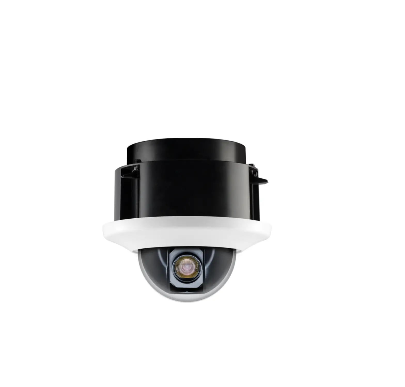
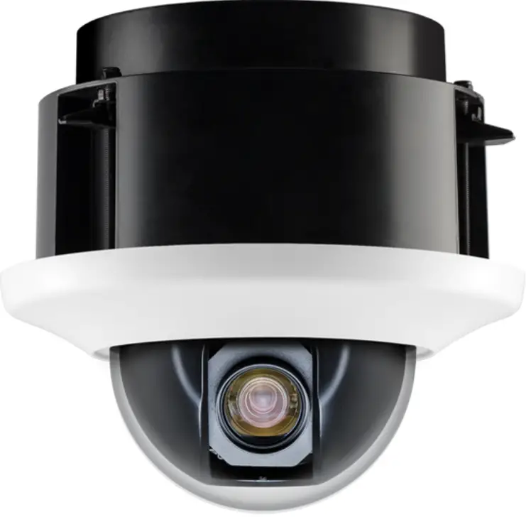
Clinton Electronics CE-PTZ10XHD HD-SDI Indoor Recess Mount PTZ
Included Items
- Camera xl
- Mount Arm x 1
- Mount Arm Silicone Gasket x 1
- Mounting Plate x 4
- Mounting Plate Silicone Gasket x 1
- Cable Harness x 1
- Installation Manual x 1
- T20 Security Torx Wrench x 1
- 1-1/2″ Phillips Head Screws x 4
- Mount Arm Screws x 3
- Cable Access Hole Plugs x 2
- Plug Tightening Tool x 1
Required Items
- Power Supply
- PTZ Keyboard
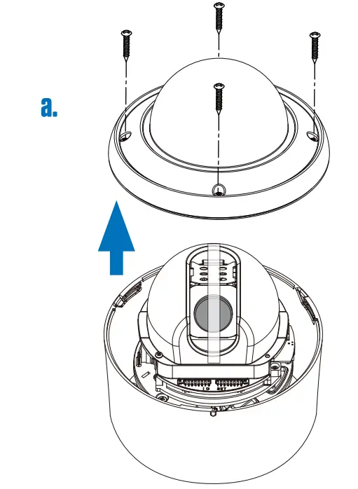
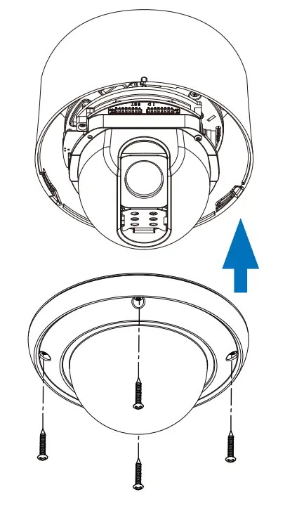
REMOVE TOP COVER & LENS COVER
a. Use the T20 security torx wrench to remove the four top cover screws, and remove the cover.
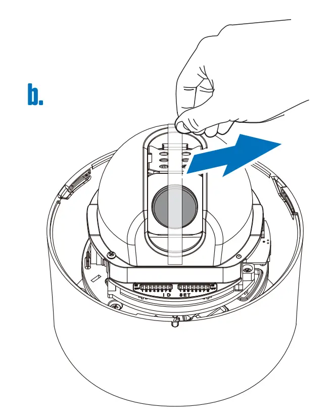
b. Peel off the tape which holds the camera lens in place, then remove the lens cover from the lens.
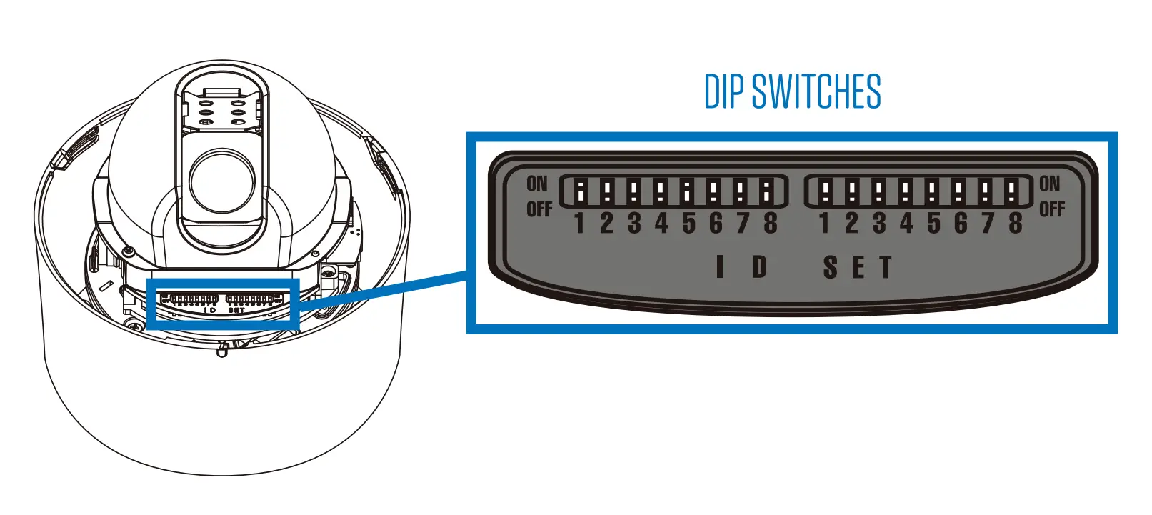
SET DIP SWITCHES
Before installing the camera, set the camera address, and protocol settings with the dip switches. Address ID and Settings dip switches can be found on the interior of the camera housing after removing the top cover.
Address ID Number
The first set of numbered switches corresponds to the device’s address ID number. When a combination of switches are set to on, the ID number will be the sum of those switches. To confirm the ID number, it will appear on-screen during the initial information boot up screen. Camera IDs can be set from 1-255.
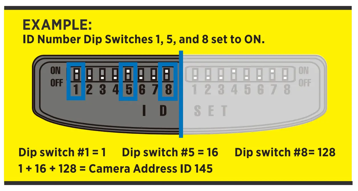
| SWITCH# | 1 | 2 | 3 | 4 | 5 | 6 | 7 | 8 |
| ID# | 1* | 2 | 4 | 8 | 16 | 32 | 64 | 128 |
*Indicates default setting
Settings
The second set of numbered switches corresponds to the PTZ’s settings .
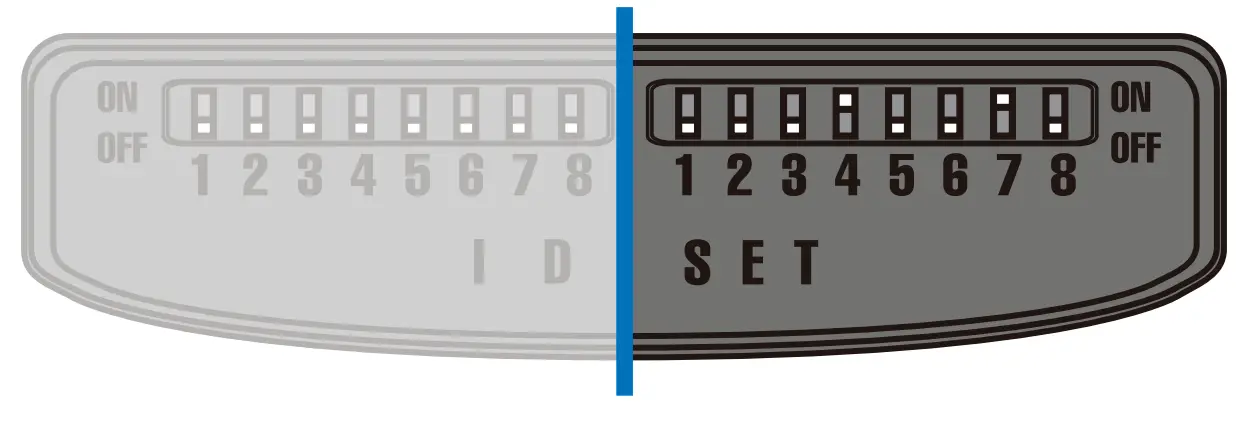
| PROTOCOL | 1 | 2 |
| CLINTON* | OFF | OFF |
| PELCO-D | OFF | ON |
| PELCO-P | ON | OFF |
| AD | ON | ON |
| BAUDRATE | 3 | 4 | 5 |
| 2400 | OFF | OFF | OFF |
| 4800* | OFF | OFF | ON |
| 9600 | OFF | ON | OFF |
| 19200 | OFF | ON | ON |
| 38400 | ON | OFF | OFF |
| 57600 | ON | OFF | ON |
| 115200 | ON | ON | OFF |
| NTSC/PAL | 6 |
| PAL | ON |
| NTSC* | OFF |
| COMM. | 7 |
| RS-485 | ON |
| RS-422* | OFF |
Dip switch 8 is disabled on this model.
*Indicates default setting
SET TERMINATION SWITCH
The device which is connected at the end of the line must have the cable communication terminated. Without proper termination, there is potential for control signal errors. The termination dip switch can be found on the bottom side of the camera body.
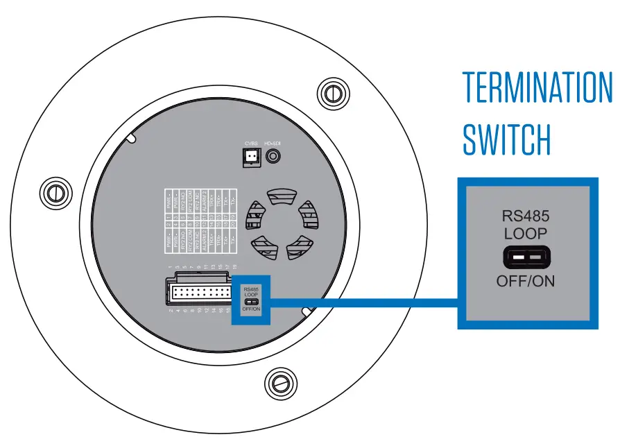
| TERMINATION | |
| TERMINATED | ON |
| NOT TERMINATED* | OFF |
*Indicates default setting
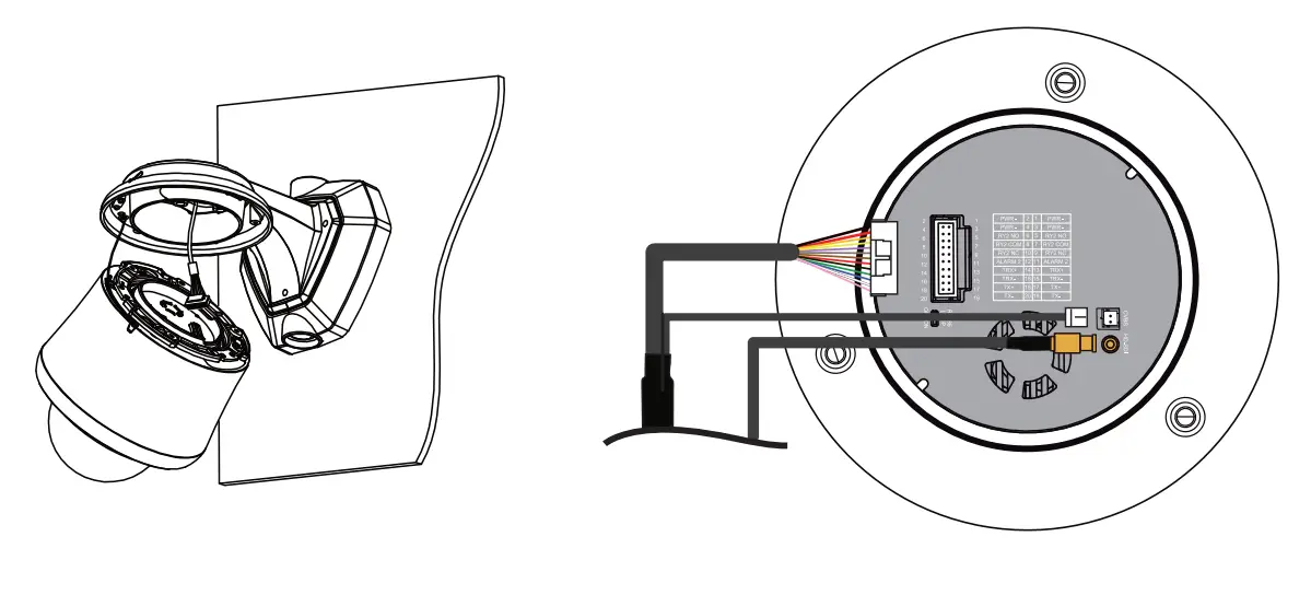
CONNECT CABLES
Before the camera can be installed, you will need to connect the power, video, and communication cables to the PTZ’s wiring harness.
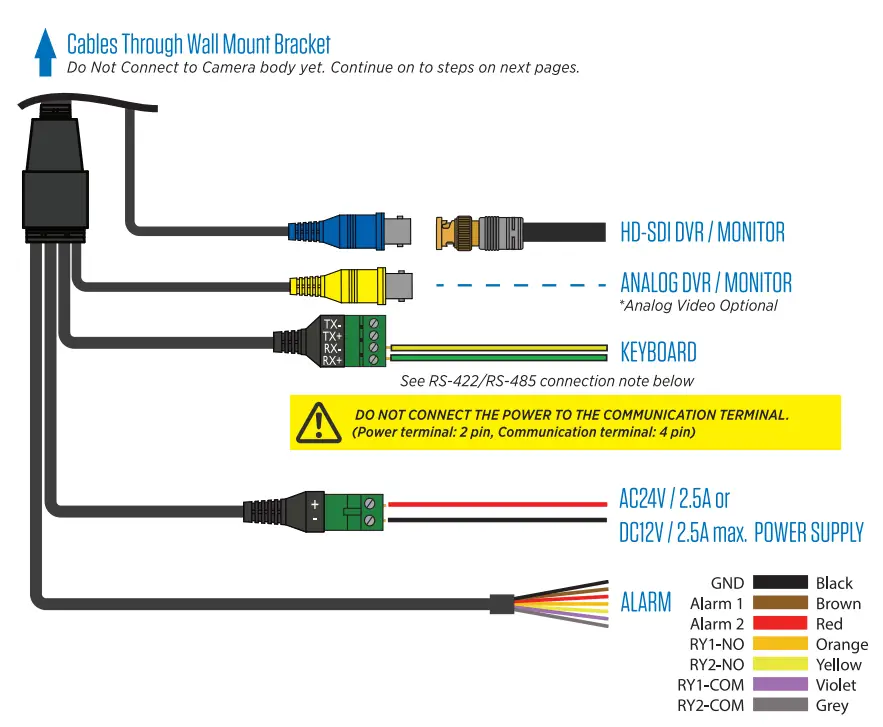
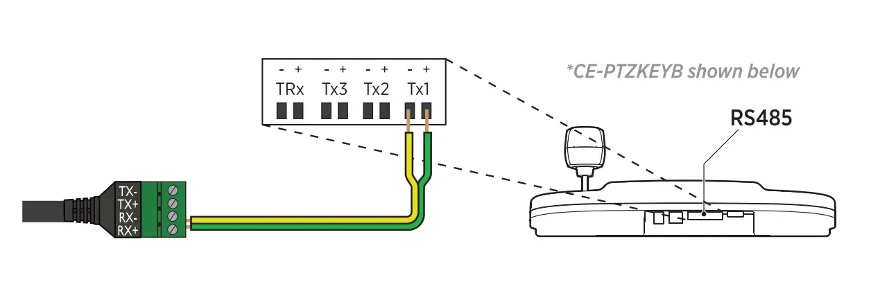
RS-422/RS-485 Connection
The PTZ can be controlled by an external device or control system such as a keyboard or DVR using the RS-485 half duplex, or RS-422 duplex or simplex serial communication signals. Connect Rx+ and Rx- on the PTZ communication cable to Tx+ and Tx- on the controller. Total length of the cable should not exceed 3,900 feet.
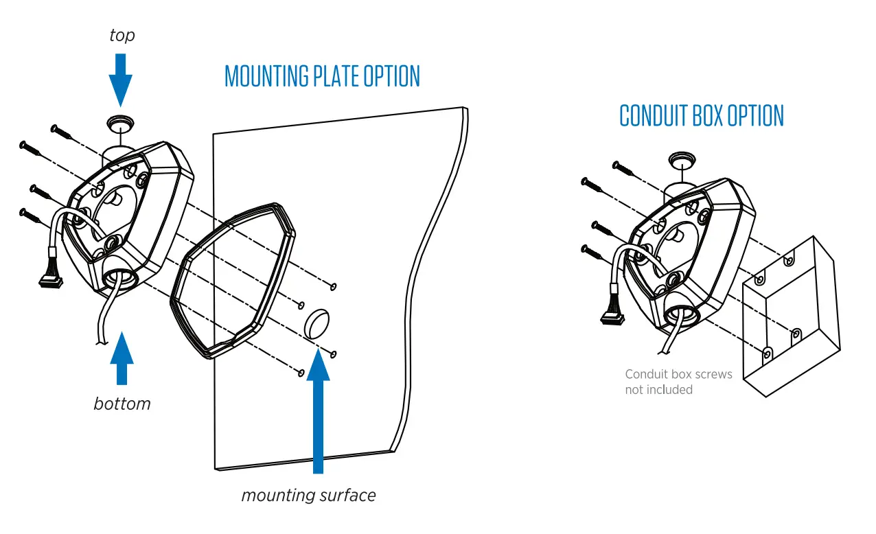
ATTACH MOUNTING PLATE
a. If mounting to a flat surface, affix the included mounting plate silicone gasket to the back side of the mounting plate.
b. Route the cable through the top, or bottom cable access hole, or through the center of the mounting plate. Cover any unused cable hole with the included hole plugs.
c. Depending on your mounting surface, attach to the plate to the mounting surface using either the four included 1-1/2″ Phillips Head screws, or use other appropriate fasteners (not included). If mounting to a double gang box, use the correct hardware for the box.
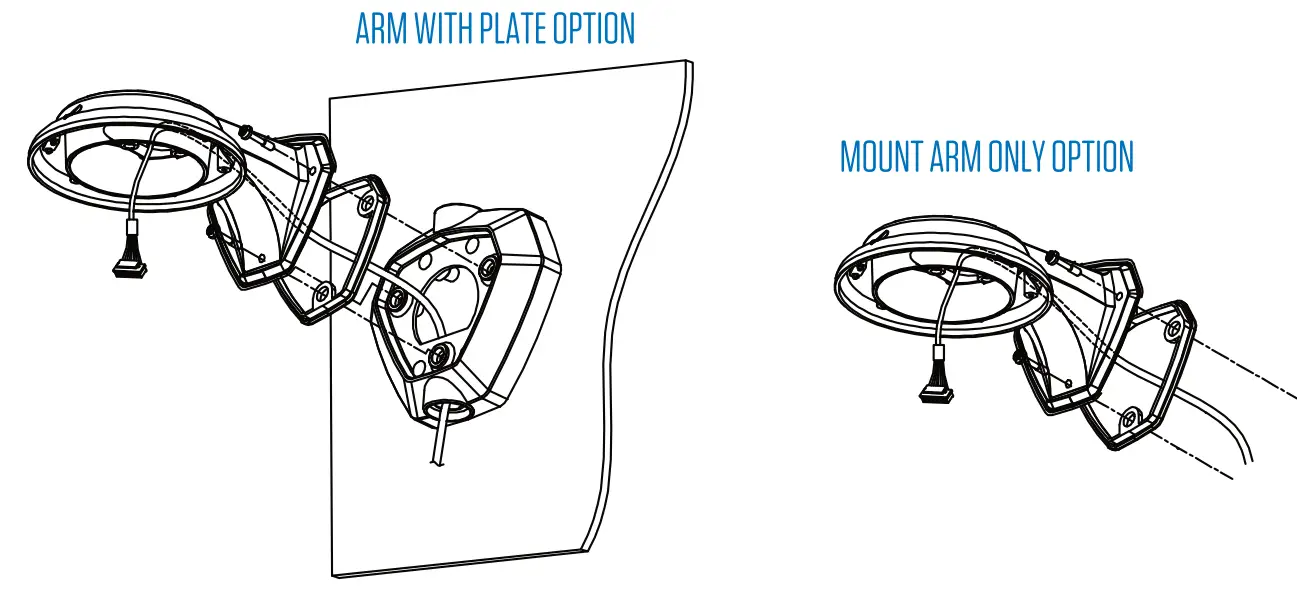
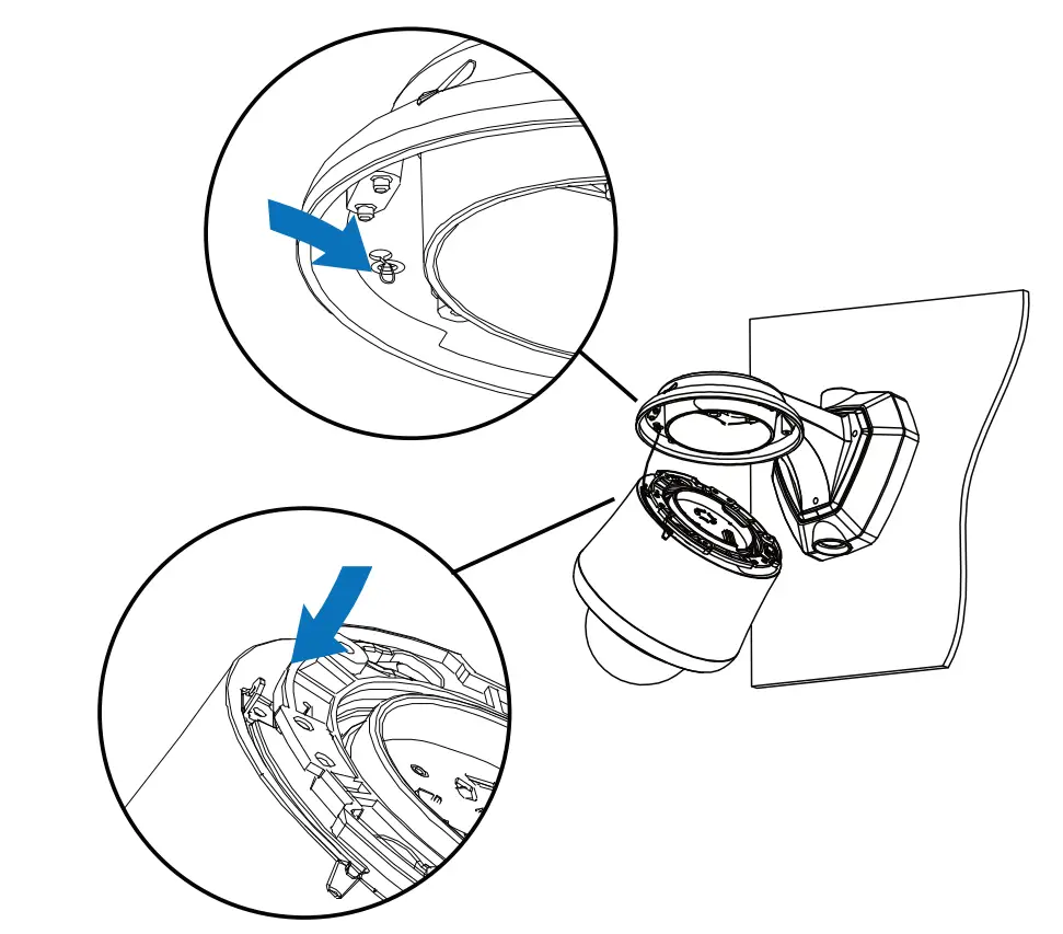
ATTACH MOUNT ARM
a. Affix the included mount arm silicone gasket to the back side of the mount arm.
b. Route the cable through the arm.
c. Attach the mount arm to the mounting plate using the three included T20 security Torx screws, or if mounting the arm without the mounting plate, use the included 1-1/2″ Phillips head screws, or other appropriate hardware.
REPLACE TOP COVER
Reattach the top cover to the camera base, and secure using the four T20 Security Torx screws.
CONNECT SAFETY LEASH
Pull the safety leash from the inside rim of the mount arm and connect the leash to the hook on the base of the camera body.
CONNECT WIRING HARNESS
Plug the end of the wiring harness into the port on the top of the camera body. Do not force the plug into the port; the plug can only be inserted one way. Insert HD-SDI and analog plugs into their respective connections.
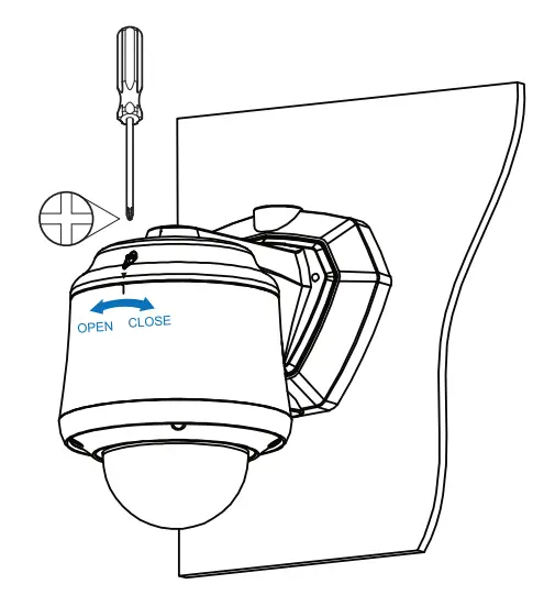
CLOSE & LOCK CAMERA TO BRACKET
a. Align the notch on the camera body to the triangle on the front center of the mount arm.
b. Rotate the camera body clockwise until the notch on the camera body aligns with the triangle on the mount arm cover.
c. Tighten the Phillips head screw on the top of the mount arm to lock the camera to the bracket.
CUSTOMER SUPPORT
Clinton electronics I 6701 Clinton Road Loves Park, IL 61111 I 800.549.6393 (Support) I www.clintonelectronics.com


