EH-ES201
Low Energy SiP Module
User Manual
19 Jan 2020 Versionl.2
Professional Bluetooth Solution Provider
VERSION HISTORY
| Version | Comment |
| V1.1 | First edition |
| V1.2 | Add antenna patterns |
Contact information
| Sales | [email protected] |
| Technical support | [email protected] |
| Website | http://www.ehonglink.com |
| Phone | +86 21 64769993 |
| Fax | +86 21 64765833 |
| Address | Rm1505,1st,No.833 South Hongmei Rd, Shanghai, China |
Introduction
EH-ES201 is a low-power Bluetooth® 5 module based on the Nordic nRF52 series platform. With the ultra-small size and powerful features. Powered by a highly efficient 64MHz 32-bit ARM® Cortex ™ M4 CPU and 192 KB Flash + 24 KB RAM.
EH-ES201 comes with a high-performance built-in antenna, which can connect up to 60m in an open environment. No external antenna is needed, and the ultra-small size of 7.0 * 7.0 * 1.4mm can reduce the PCB area requirements of customers’ products and help customers realize ultra-small products.
After purchasing EH-ES201, we will provide free technical support for the APP of the IOS system or the APP of the Android system.
Applications
|
|
Pin Descriptions
3.1 Pin-out
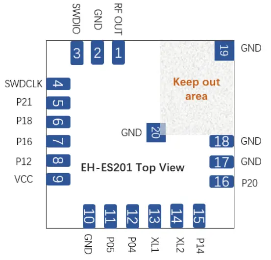
3.2 Pin Descriptions
| Pin | No. | Function | Remark |
| ROUTE | 1 | Support external antenna | |
| GND | 2 | GND pin | Power GND |
| STUDIO | 3 | Support SWD | |
| SWDCLK | 4 | Support SWD | |
| P21 | 5 | Reset | Reset |
| P18 | 6 | General input/output | |
| P16 | 7 | General input/output | |
| P12 | 8 | General input/output | |
| VCC | 9 | 1.7-3.6V | Connect a capacitor |
| GND | 10 | GND pin | Power GND |
| P05 | 11 | General input/output | |
| PO4 | 12 | General input/output | |
| XL1 | 13 | Connect external 32MHz crystal |
| XL2 | 14 | Connect external 32MHz crystal | |
| P14 | 15 | General input/output | |
| P20 | 16 | General input/output | |
| GND | 17 | Power GND | |
| GND | 18 | Power GND | |
| GND | 19 | Power GND | |
| GND | 20 | Power GND |
Note:
- MP test points should be reserved, including UART TX, UART RX, and RESET.
- For debugging, it is recommended to keep the SWDIO and SWDCLK test points.
- If used with an MCU chip, it is recommended to connect the reset pin.
Electrical Specifications
4.1 7.1 Recommended Operation Conditions
| Operating Condition | Min | Typical | Max | Unit |
| Operating Temperature Range | -30 | +25 | +85 | °C |
| Storage Temperature Range | -40 | +25 | +85 | °C |
| Working Voltage | 2. | +3.0 | 4. | V |
| Voltage for module | 2. | – | 4. | V |
| I/O Supply Voltage (VDD_PIO) | 0. | +3.0 | +3.6 | V |
| A10 input | 0 | – | VDD BAT | V |
| Frequency range | 2402 | – | 2480 | MHz |
Note: Terminal voltages other than RF
4.2 Module power consumption
| Power mode | Current Consumption(Max) |
| Transmission mode (3V DC/DC ) | 7.0 mA, Active TX mode( TX power:3.5dBm) |
| 4.6 mA, Active TX mode( TX power:3.5dBm) | |
| 4.6 mA, Active RX mode( 1M of 2M) | |
| Standby mode (3V DC/DC ) | 0.3 pA in System OFF, no RAM retention |
| 0.5 pA in System OFF, full RAM retention | |
| 0.6 pA in System ON, no RAM retention | |
| 0.8 pA in System ON, full RAM retention | |
| System current consumption (3V DC/DC) | 1.5 pA in System ON, full RAM retention and RTC |
- minimum power consumption:Condition: VBAT=3V, VDDIO=3V, ambient temperature:25℃.
Software/ Firmware
| Software Support | |
| Standard Software | Thong provides the module with standard software for customers to develop. Support to make some modifications and support customized MAC address |
| SDK development | Thong provides SDK and description |
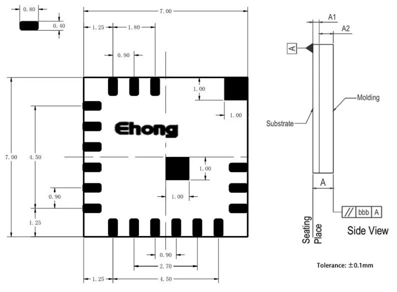
Mechanical Data
6.1 Dimensions and recommend PCB
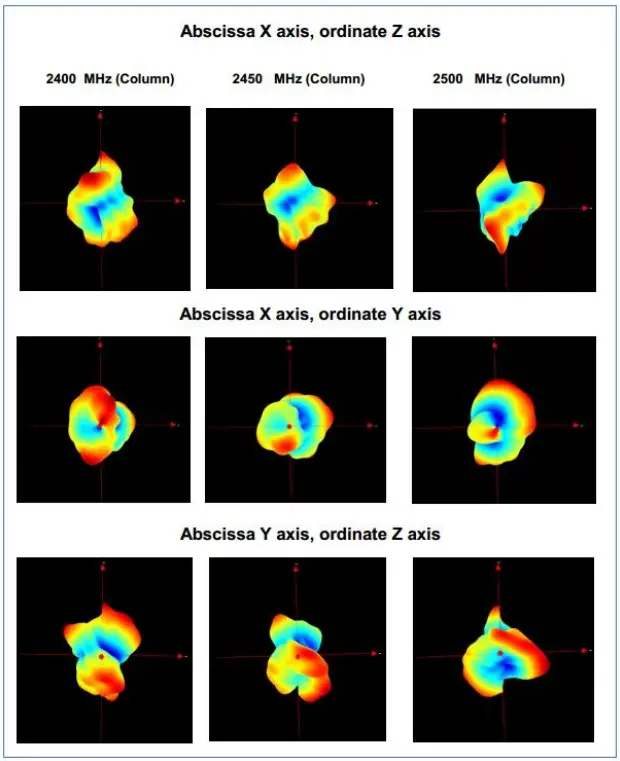
Antenna Patterns
Antenna patterns are based on the EH-ES201 Evaluation Kit
Layout suggestion
8.1 Power supply precautions
- Module power: 3v button battery or DC 3.3v
- Connect the power pin capacitors as close as possible to the chip and pins
- Use capacitors to decouple power from the chip
- Use capacitors to prevent noise from coupling back into the power plane
Note: When supplying power to the module, it is necessary to use a small ripple (generally, the power ripple within 30mV is sufficient). It is recommended to use the LDO to power the module when selecting the power supply. The LDO PCB layout needs to be away from some inductive sensor, DC-DC power supply \ inductance, etc., in the PCB design, it is necessary to have a reliable grounding process, and it must not exceed the maximum voltage used by the module to prevent the module from irrecoverable damage.
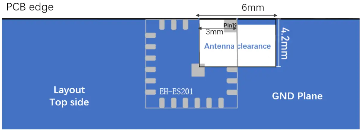
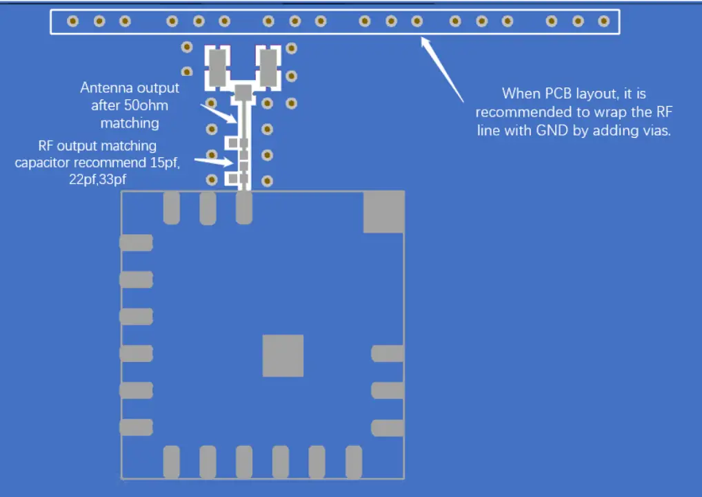
8.2 Layout Guidelines
For ES201, the integrated antenna needs a proper ground plane to radiate efficiently.
The area protruding from under the antenna section of the module should be free of copper and other metals.
The module should be placed on the edge of the PCB with the antenna edge facing outward.
The antenna needs to be processed for clearance during layout and requires a sufficient clearance area. (When designing, pay attention to both the top and bottom layers. If conditions allow, it is recommended to hollow out the clearance directly when designing the PCB board. No form of electrical operation is allowed in the projection area of the antenna to ensure the radiation effect of the antenna.
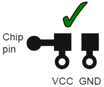
Note: Pin19 Needs to be grounded.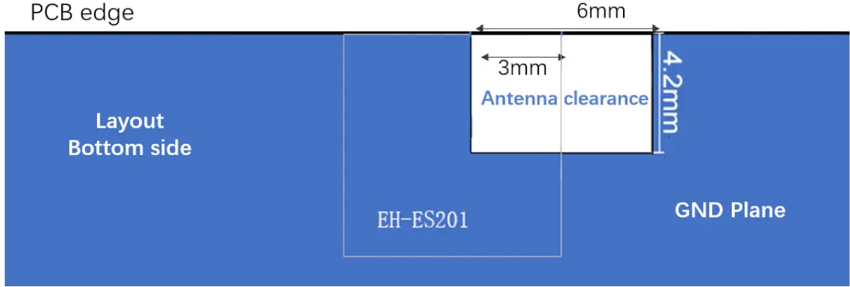
8.3 EH-ES201 PCB layout
Packaging and Labeling
Each reel or tray will be placed in an antistatic bag with a desiccant bag and a humidity card and in a 36x25x12cm box. Antistatic warnings and labels are attached to the outside of the packaging.
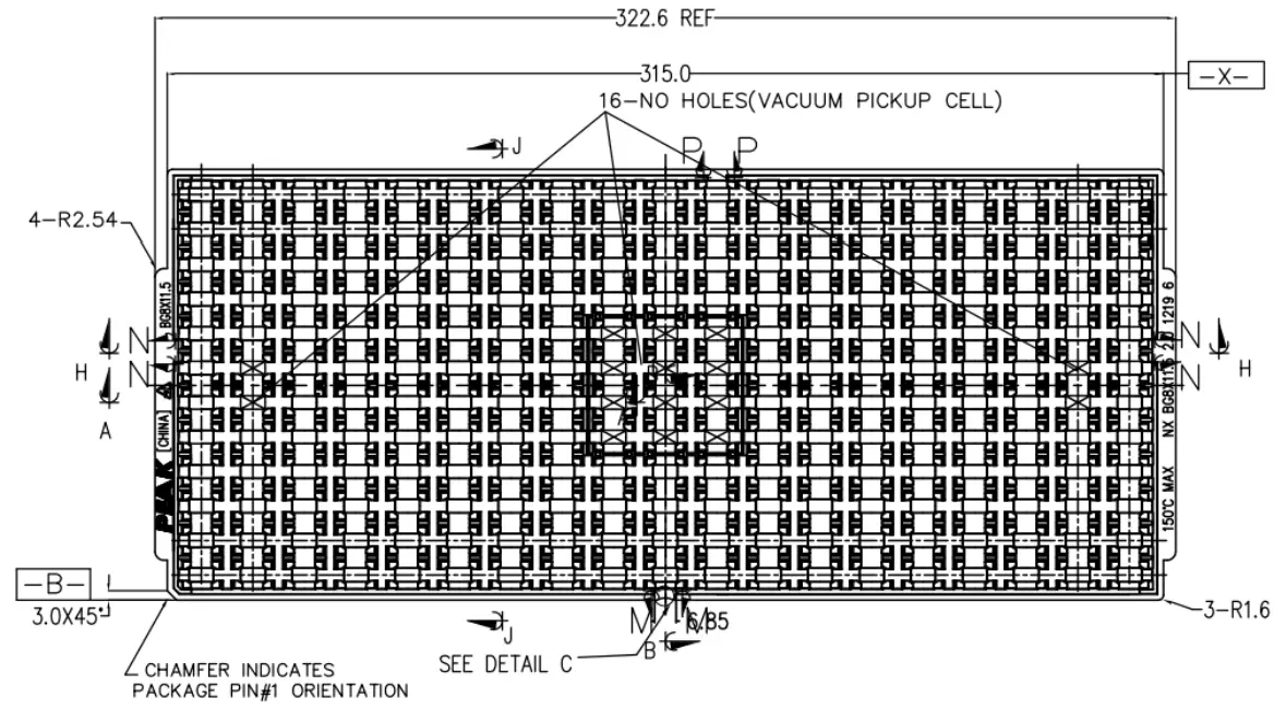
9.1 Tray package
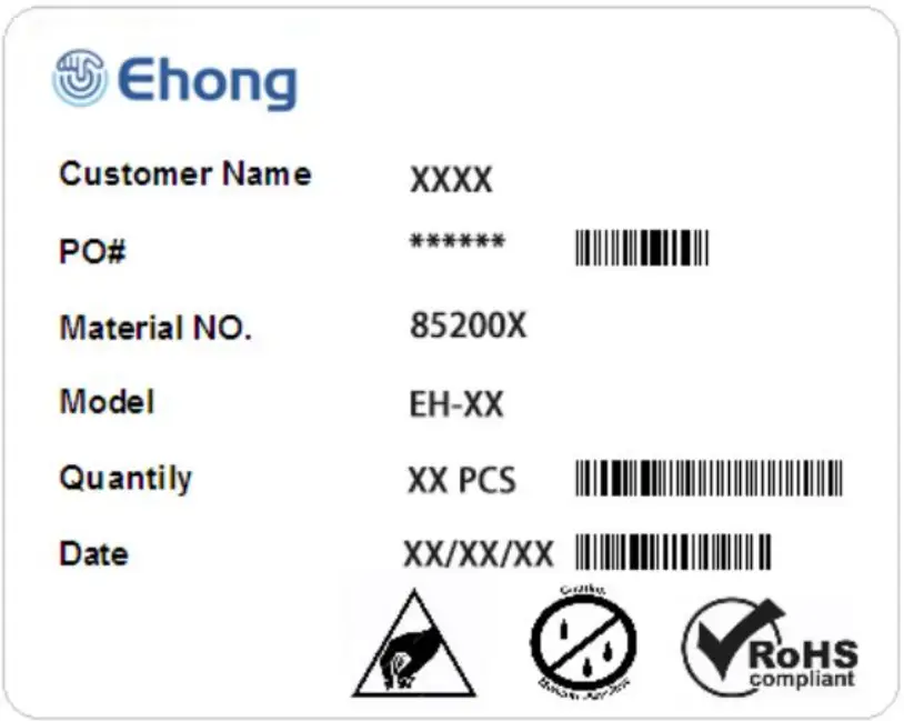
9.2 Packing Label
Phone Documents:
Visit the website and download:
Supports:[email protected]
Sales: [email protected]
phone: +0086 021-54769993-201
OEM Guidance
- Applicable FCC rules
This module is granted Single Modular Approval. It complies with the requirements of FCC part 15C, section 15.247 rules. - The specific operational use conditions
This module can be used in IoT devices. The input voltage to the module is nominal 1.7V-3.6 V DC. The operational ambient temperature of the module is –40 °C ~ 85 °C. - Limited module procedures
N/A - Trace antenna design
N/A - RF exposure considerations
The equipment complies with FCC radiation exposure limits set forth for an uncontrolled environment. This equipment can operate with a minimum distance of 5mm between the radiator and your body. - Antenna
Antenna type: Patch Antenna Antenna gain : 0dBi - Label and compliance information
An exterior label on OEM’s end product can use wording such as the following: “Contains Transmitter Module FCC ID: 2ACCRES201” or “Contains FCC ID: 2ACCRES201” - Information on test modes and additional testing requirements
a)The modular transmitter has been fully tested by the module grantee on the required number of channels, modulation types, and modes, it should not be necessary for the host installer to re-test all the available transmitter modes or settings. It is recommended that the host product manufacturer, installing the modular transmitter, perform some investigative measurements to confirm that the resulting composite system does not exceed the spurious emissions limits or band edge limits (e.g., where a different antenna may be causing additional emissions).
b)The testing should check for emissions that may occur due to the intermixing of emissions with the other transmitters, digital circuitry, or due to physical properties of the host product (enclosure). This investigation is especially important when integrating multiple modular transmitters where the certification is based on testing each of them in a stand-alone configuration. It is important to note that host product manufacturers should not assume that because the modular transmitter is certified that they do not have any responsibility for final product compliance.
c)If the investigation indicates a compliance concern the host product manufacturer is obligated to mitigate the issue. Host products using a modular transmitter are subject to all the applicable individual technical rules as well as to the general conditions of operation in Sections 15.5, 15.15, and 15.29 to not cause interference. The operator of the host product will be obligated to stop operating the device until the interference has been corrected. - Additional testing, Part 15 Subpart B disclaimer The final host/module combination needs to be evaluated against the FCC Part 15B criteria for unintentional radiators in order to be properly authorized for operation as a Part 15 digital device.
The host integrator installing this module into their product must ensure that the final composite product complies with the FCC requirements by a technical assessment or evaluation of the FCC rules, including the transmitter operation, and should refer to guidance in KDB 996369. For host products with the certified modular transmitters, the frequency range of investigation of the composite system is specified by a rule in Sections 15.33(a)(1) through (a)(3), or the range applicable to the digital device, as shown in Section 15.33(b)(1), whichever is the higher frequency range of investigation
When testing the host product, all the transmitters must be operating. The transmitters can be enabled by using publicly-available drivers and turned on, so the transmitters are active.
In certain conditions, it might be appropriate to use a technology-specific call box (test set) where accessory 50 devices or drivers are not available. When testing for emissions from the unintentional radiator, the transmitter shall be placed in the receive mode or idle mode, if possible. If receive mode only is not possible then, the radio shall be passive (preferred) and/or active scanning. In these cases, this would need to enable activity on the communication BUS (i.e., PCIe, SDIO, USB) to ensure the unintentional radiator circuitry is enabled. Testing laboratories may need to add attenuation or filters depending on the signal strength of any active beacons (if applicable) from the enabled radio(s). See ANSI C63.4, ANSI C63.10, and ANSI C63.26 for further general testing details.
The product under test is set into a link/association with a partnering device, as per the normal intended use of the product. To ease testing, the product under test is set to transmit at a high duty cycle, such as by sending a file or streaming some media content.
FCC Warning:
Any changes or modifications not expressly approved by the party responsible for compliance could void the user’s authority to operate the equipment. This device complies with part 15 of the FCC Rules. Operation is subject to the following two conditions: (1) This device may not cause harmful interference, and (2) This device must accept any interference received, including interference that may cause undesired operation
ISED RSS Warning:
This device complies with Innovation, Science, and Economic Development Canada licence‐exempt RSS standard(s). Operation is subject to the following two conditions:
(1) this device may not cause interference, and
(2) this device must accept any interference, including interference that may cause undesired operation of the device.
ISED RF exposure statement:
This equipment complies with ISED radiation exposure limits set forth for an uncontrolled environment. The device has been evaluated to meet general RF exposure requirements.
IC Label Instructions:
The outside of final products that contain this module device must display a label referring to the enclosed module. This exterior label can use wording such as:
“Contains Transmitter Module IC: 20625-ES201”, or “Contains IC: 20625-ES201”, Any similar wording that expresses the same meaning may be used.


