HiBOOST F20G-5S-BTW Smartlink Series Smartlink Cell Signal Booster Installation Guide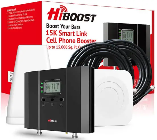
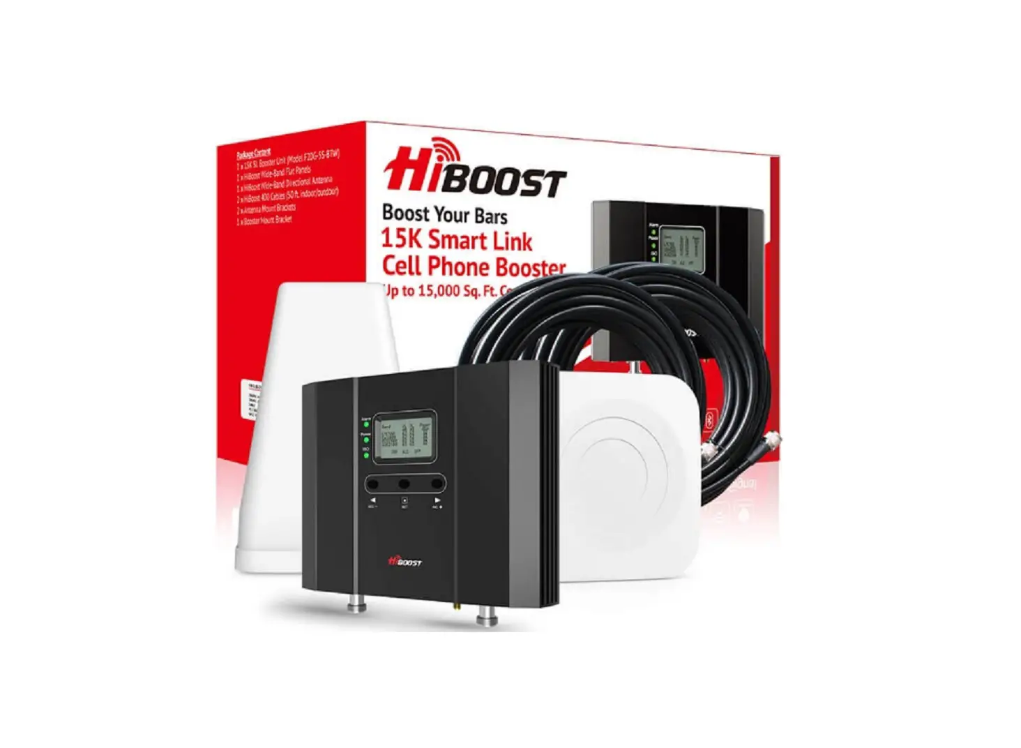
Package Contents
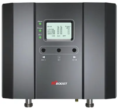
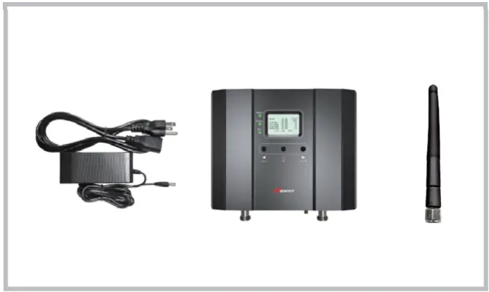
- Signal Booster

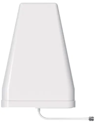
- Outside Antenna

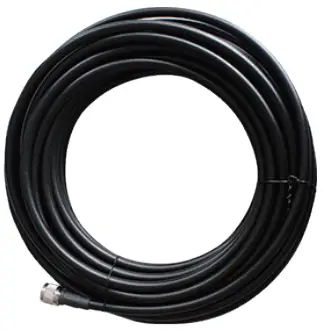
- 50ft Outdoor Cable

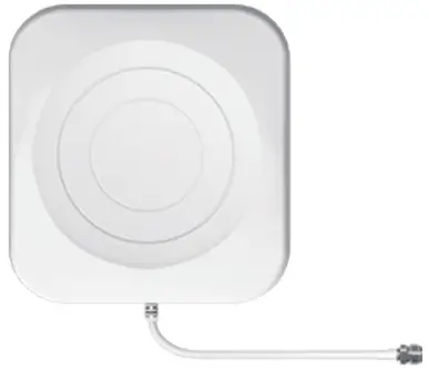
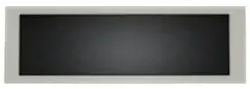
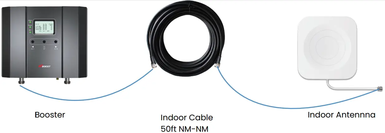
- Indoor Antenna

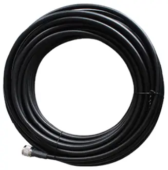
- 50ft Indoor Cable

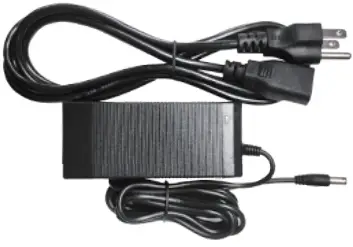
- Power Supply

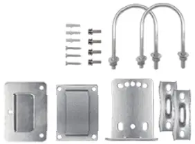
- Accessories for main parts are all provided

- 3M waterproof tape to protect connections

- Bluetooth and Wi-Fi antenna

Getting Started
Step 1 Connect the Power Supply and the whip antenna to the Booster
Step 2 Download the Signal Supervisor App, register ID and booster.
- Register an ID first and log in.
- Add the booster to the device list.

Step 3 Find the cell tower & Determine the outdoor antenna’s position
Find the band you are using
For Android
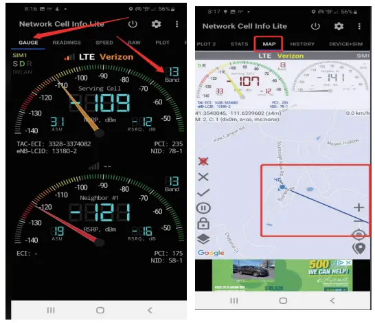
Download NetWork Cell Info Lite in the Google store and open it.
It can be seen that the frequency band is band 13 from the example picture.
Then click MAP. You can see your phone connecting to a tower, and you can try aiming your outdoor antenna at it. But sometimes this is not accurate.You could also follow Step 3.2 to find the tower.
Note: Please take screenshots at this stage.
For ios
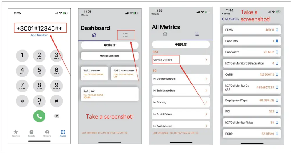
- Dial *3001#12345#*
- Follow the instructions, take the screenshots as requested
Find the cell tower
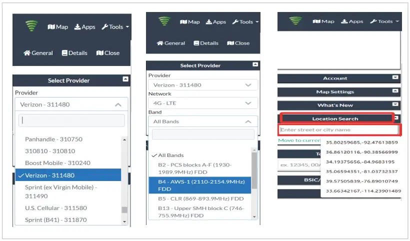
- Enter cellmapper.net
- Choose your own carrier and band here.
- Then enter the coordinate of where you are trying to install the signal booster, and press Enter key.
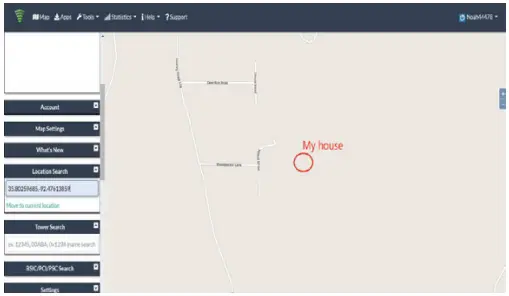
(In fact when you open Cell mapper, the map on the right will automatically locate your area if you’ve given the site permission to access your location. If you found tower sites that were not even showing up on the map, it may because the app offsets the locations for security reasons.) - The map on your right will jump to the location, then you can scroll the mouse pulley, zoom it out, you will see the tower near the location. And
better to take a screenshot of this page for guiding the following installing steps. If you have any questions, please contact our tech support.
Note: If you need help finding the tower, please contact our tech support and provide your carrier, band and screenshots taken in the last steps.
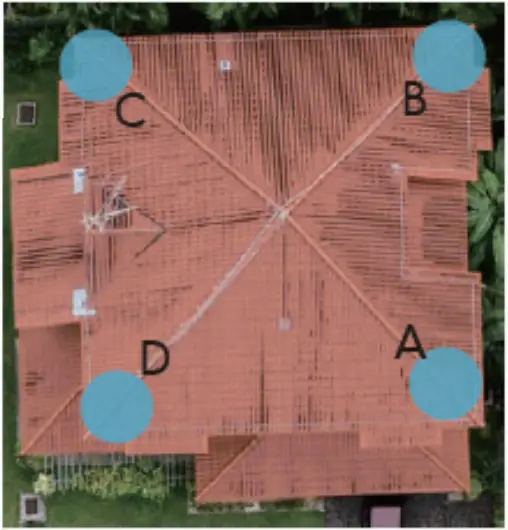
Determine the outdoor antenna’s position
The outdoor antenna is usually placed at one of the 4 ends of the roof.
Please choose the position according to the tower’s location. Make sure
there are no barriers between the antenna and the tower.
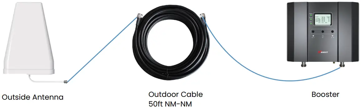
Connect the outdoor antenna with the booster
Note:At this stage, don’t connect the indoor antenna to the booster.
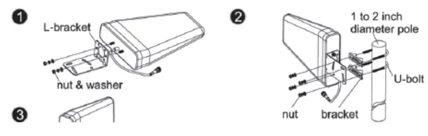
Adjust and fix the Outdoor Antenna
Have your outdoor antenna pointed to the cell tower you found before and watch the readings on the app. Adjust the outdoor antenna.
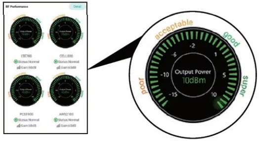
Notes:
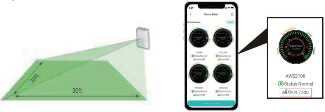
- The output power should be the higher the better.
- The full output power for 15k Smartlink is 12dBm. And the full gain is 72dB.
Connect the indoor antenna with the booster
Adjust the indoor antenna
Have your indoor antenna pointed to the area you would like to cover with signal.
Notes:
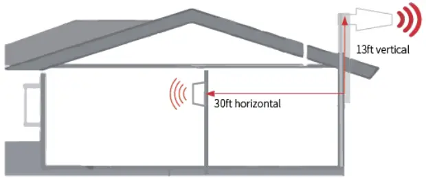
- It would be best if you could make the two antennas face opposite directions.
- Make sure that the gain reaches 72dB. If not, please adjust the direction of the indoor antenna/increase the vertical and horizontal distance between the two antennas/add some barriers.
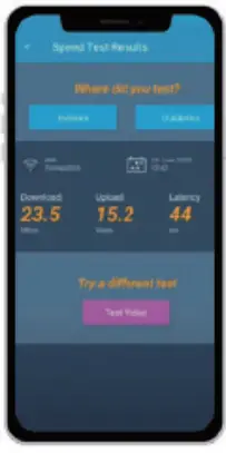
Signal quality test
You could do the following:
- Do speed tests with the booster on and off, and make a comparison.
- Check if the number of signal bars increases.
- Make a phone call or send messages and check if the voice and streaming are better.

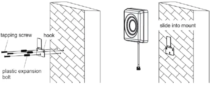
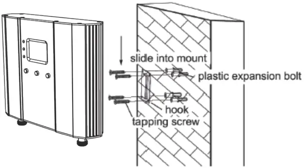
Fix the Inside Antenna and the Booster
- Fix the indoor antenna with the provided expansion bolt and hook.

- Fix the booster with the provided expansion bolt and hook.

Regular Problems and 1 normal status
| (UL)Gain | (DL)Gain | (DL)Output Power | LED Light Indicator | Reason | Method | |
| Overload | <72dB | <72dB | >=12dBm | Alarm light blinking green or red | Outdoor Signal Too Strong | Have your outdoor antenna pointed slightly off the cell tower |
| Loop Back | <72dB | <72dB | <12dBm | ISO light blinking green or red | Separation of the Two Antennas Not Good Enough |
|
| Poor Input Signal | =72dB | =72dB | — | Alarm and ISO lights both solid green | Outdoor Signal Too Weak | Try adjusting the outdoor antenna or using another cell tower |
| Normal but No Boosted Signal | =72dB | =72dB | Positive | Alarm and ISO lights both solid green | The Signal is from Other Bands or Carriers | Try adjusting the outdoor antenna again. It would be better if there are two persons and one can stay near the indoor antenna to check if the signal is boosted. |
| Normal | =72dB | =72dB | Positive |
Bands contained in the Gauges
| Gauge | Band | Uplink | Downlink |
| LTE700 | 12/17 | 698-716MHz | 728-746MHz |
| 13 | 776-787MHz | 746-757MHz | |
| CELL800 | 5 | 824-849MHz | 869-894MHz |
| PCS1900 | 25/2 | 1850-1915MHz | 1930-1995MHz |
| AWS2100 | 4 | 1710-1755MHz | 2110-2155MHz |
Note:
Some customers have some misunderstandings about boosters, and we would like to clarify it here
If you can’t even get a stable 1 bar outside the house or on the roof, then we suggest you return it as it won’t work in areas with very weak signal, the same is true of all boosters on the market.
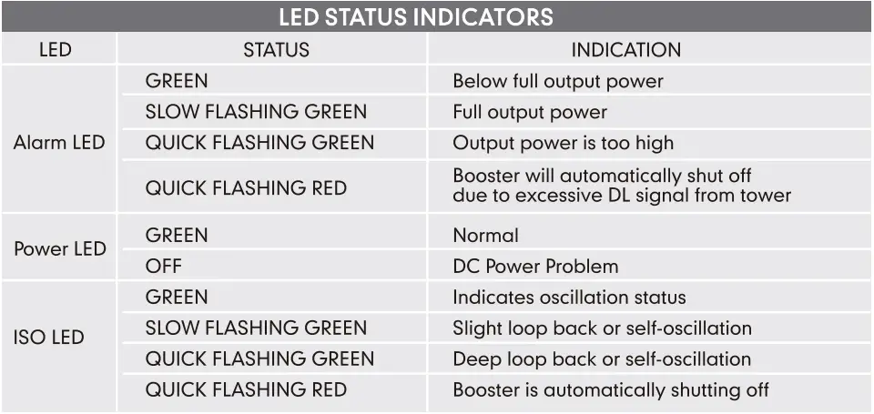
Booster Light Patterns
Technical Specifications
| Model No. | 4K Smart Link | 10K Smart Link | 15K Smart Link |
| Working Bands | Band 12/17/Band 13/Band 5/Band 25/2/Band 4 | ||
| UL Frequency Range | 698-716 / 776-787 / 824-849 / 1850-1915 / 1710-1755 | ||
| DL Frequency Range | 728-746 / 746-757 / 869-894 / 1930-1995 / 2110-2155 | ||
| Maximum Gain | 60 dB | 65 dB | 72 dB |
| Maximum Output Power | UL 24 dBm, DL 10 dBm | UL 24 dBm, DL 12 dBm | |
| I/O Port | N-Female & SMA-Female | ||
| Weight | > 4.0 lb / 1.8 kg | > 5.0 lb / 2.2 kg | |
| Dimensions | 4.7in x 7.8in x1.4in / 120mm x 198mm x 34mm | 8.6in x 6.5in x 2in / 218mm x 165mm x 50mm | |
| MGC(Step Attenuation) | >25 dB /1 dB Step | ||
| Impedance | 50 ohm | ||
| Environment Condition | IP40 | ||
| Power Supply | Input AC 100~240V, 50/60Hz, Output DC 12 V/3 A | ||
For more information
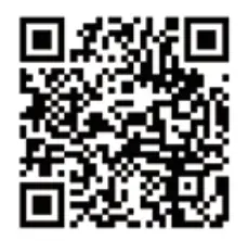
Download Signal Supervisor or enter our website.
- You can download the specific user manual.
- You can reach our technical support for help.
3150 Premier Drive,Suite 130,
Irving, TX 75063
(972) 870-5666
[email protected]
www.hiboost.com


