IDYLIS 0530393 Portable Air Conditioner with Heater User Manual

IDYLIS 0530393 Portable Air Conditioner with Heater User Manual
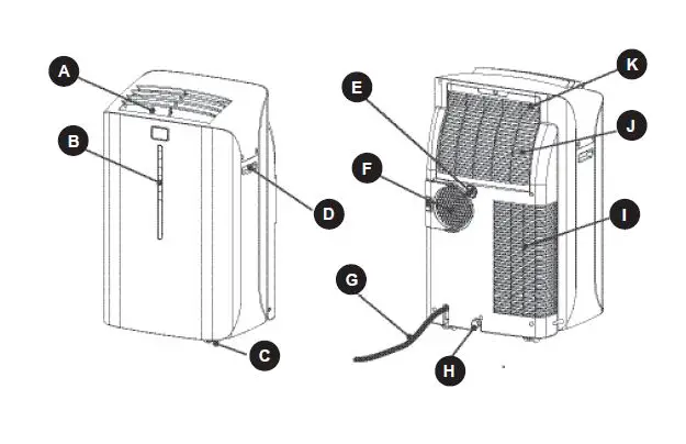
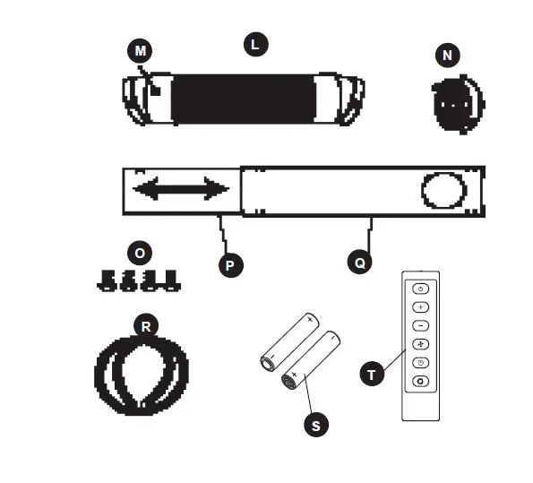
PACKAGE CONTENTS
| PART DESCRIPTION QUANTITY | ||
| A | Air Outlet | 1 |
| B | Control Panel | 1 |
| C | Castor | 4 |
| D | Handle Hole | 1 |
| E | Water Outlet Drain | 1 |
| F | Air Exhaust | 1 |
| G | Power Supply Cord | 1 |
| H | Water Outlet Drain | 1 |
| I | Air Intake (Condensor) | 1 |
| J | Air Intake (Evaporator) | 1 |
| K | Air Filter | 1 |
| PART DESCRIPTION QUANTITY | ||
| L | Flexible Exhaust Hose | 1 |
| M | Exhaust Nozzle Connector | 2 |
| N | Tube Adapter | 1 |
| O | Screw | 4 |
| P | Window Panel Extension | 1 |
| Q | Window Panel | 1 |
| R | Drain hose | 1 |
| S | AAA Batteries | 2 |
| T | Remote | 1 |
SAFETY INFORMATION
Please read and understand this entire manual before attempting to assemble, operate or install the product.Portable air conditioners exhaust large amounts of room air. Always ensure an adequate supply of make-up air to operate effi ciently.
- Check available power supply and resolve any wiring problems BEFORE installation and operation of this unit. All wiring must comply with local and national electrical codes and be installed by a qualifi ed electrician. If you have any questions regarding the following instructions, contact a qualifi ed electrician.
- This appliance draws 9.5 nameplate amps and may be used in any properly wired general purpose 15 amp household grounded receptacle.
- For your safety and protection, this unit is grounded through the power cord plug when plugged into a matching wall outlet. If you are not sure whether the wall outlets in your home are properly grounded, consult a qualifi ed electrician.
WARNING
- Improper connection of the grounding plug can result in risk of fi re, electric shock, and/or injury to persons associated with the appliance. Check with a qualifi ed service representative if in doubt that the appliance is properly grounded.
- DO NOT USE PLUG ADAPTERS OR EXTENSION CORDS WITH THIS UNIT. If it is necessary to use an extension cord with this unit, use an approved “air conditioner” extension cord only.
- To avoid the possibility of personal injury, always disconnect the power supply to the unit before installing and/or servicing.
POWER SUPPLY CORD
The power cord supplied with this air conditioner contains a device that senses damage to the power cord. To test if your power cord is working properly, you must do the following:
- Connect the power supply cord to an electrical outlet.
- The power supply cord has two buttons located on the head of the plug. One button is marked “TEST” and the other is marked “RESET.” Press the “TEST” button; you will hear a click as the “RESET” button pops out.
- Press the “RESET” button; you will hear a click as the button engages.
- The power supply cord is now energized and supplying electricity to the air conditioner (on some products this is also indicated by a light on the plug head.)
Note:
The power cord supplied with this air conditioner contains a current leakage detection device designed to reduce the risk of fi re. In the event the power supply cord is damaged, it cannot be repaired and must be replaced with a new cord from the product manufacturer. - Under no circumstance should this device be used to turn the unit on or off.
- The reset button must always be pushed in (engaged) for correct operation.
- The power supply cord must be replaced if it fails to reset when the “TEST” button is pushed in.
PREPARATION
Before beginning assembly of product, make sure all parts are present. Compare parts with package contents list. If any part is missing or damaged, do not attempt to assemble the product.
Estimated Assembly Time: 20 minutes
Tools Required for Assembly (not included): Phillips Screwdriver
ASSEMBLY INSTRUCTIONS
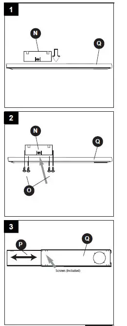
- Insert tube adapter (N) through the back of the hole in the window panel (Q).
- Using the 4 screws (O) supplied, secure the tube adapter (N) from the front of the window panel (Q).
- . Insert window panel extension (P) into the window panel (Q). Lightly tighten the pre-assembled screws in the window panel to hold the extension in place.
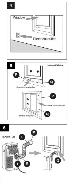
- Select a suitable location for the unit, making sure you have access to an electrical outlet.

- Install the window panel by expanding it to fi t the length of the window and fully tightening the pre-assembled screws in the middle.
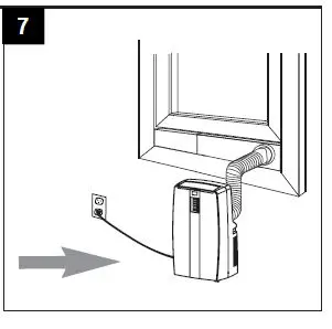
- Attach an exhaust nozzle connector (M) to each side of the exhaust hose (L). (The exhaust hose has a min. length of 21-13/20 in. when unstretched and a max. length 66-3/20 in.) Then, install one end of the exhaust hose (L) to the air exhaust (F) on the right rear side of the unit and the other end of the exhaust hose into the opening in the window panel (Q).
- Plug the unit into a 115V/60Hz grounded electrical outlet.

OPERATING INSTRUCTIONS
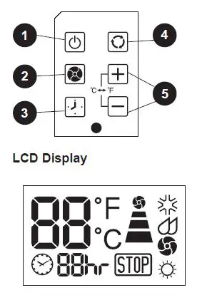
- Power switch: Turns unit on/off
- Fan: Select from three different fan settings: high, medium, and low.
- Auto timer
- Mode: Allows you to scroll through desired operating modes.
- Up/down buttons: By pressing both “+” and “-” buttons at the same time for more than 3 seconds, the display will toggle between Celsius and Fahrenheit.
Warning light:
Condensed water may accumulate in the unit. If the internal tank becomes full, the warning signal in the LCD display will light up and the unit will not operate until it has been drained
Note:
After turning the unit off, it is necessary to wait 3 minutes before turning it back on again.
AIR CONDITIONING
Note: The exhaust hose must be properly vented outdoors during air conditioning mode.
- Press the POWER SWITCH button to switch on the unit, and the most recent set temperature will be shown in the temperature display area of the control panel.
- Press the MODE button until the COOL indicator light illuminates on the control panel. Each depression of the MODE button will advance to a different mode setting (Cool – Dehumidifi er – Fan – Heat.)
- Press the appropriate increase “+” or decrease “-” buttons to select a suitable operating temperature setting. Temperature settings are adjustable between 16°C (61°F) to 32°C (89°F.)
- Press the FAN button to select the desired fan speed setting (High-Med-Low.) Your selection will appear on the control panel (each depression of the fan key will advance to a different setting.)Cooling stops automatically when the set temperature is achieved. Cooling resumes when the room temperature rises above the ‘set’ temperature level.
DRAINING EXCESS WATER
If the water tank in the unit becomes full, a ‘full tank’ indicator light will come on. To drain excess water: 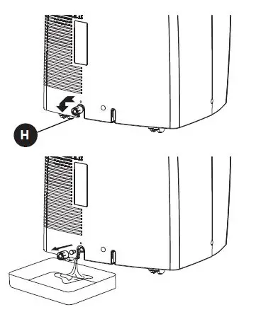
- Begin by placing a pan under the water outlet drain (H).
- Unscrew the drain cover and remove the soft rubber stopper. Let the water drain into the pan. When the water stops draining out, replace the soft rubber stopper and tighten the drain cover.
- Remove the pan of water and empty into a sink.
- Operate the unit in Fan Mode to dry the interior of the unit.
DEHUMIDIFIER:
Note: During dehumidifi er mode, the exhaust hose does not have to be vented outdoors.’
- Press the ON/OFF key pad to switch the unit on.
- Press the MODE key until the DEHUMIDIFY indicator illuminates on the control panel. Each press of the MODE key will advance to a different mode setting(Cool-Dehumidifi er-Fan-Heat.)
IMPORTANT:
There is no temperature adjustment during dehumidifi er mode. If the room temperature is greater than 77°F (26°C), the fan speed can be adjusted. Otherwise the fan speed is fi xed at LOW speed.
INSTALLING DRAIN HOSE
IMPORTANT:
The drain hose (R) must be installed during dehumidifi er mode. The continuous drain function can be set up using the following steps: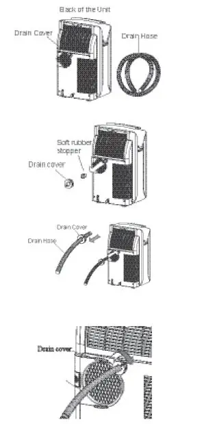
- To save having to frequently empty the water tank, this unit can be confi gured for continuous drain. You can use the supplied drain hose (R) to connect the continuous drain connector.
- Unscrew and remove the drain cover from the drain port at the rear of the unit.
- Remove the soft rubber stopper from the drain cover and place it in the water tank for safe keeping.
- Insert the drain hose (R) through the hole of the drain cover.
- insure the rubber seal ring is properly seated in the end of the hose.
- Connect the drain hose (R) to the water outlet drain (E).
- Tighten the drain cover clockwise onto the rear of the unit.
- Place the opposite end of the drain hose into a fl oor drain or another basin.
When using the continuous drain function, the drain hose must be placed horizontally below the drainage hole. Avoid uneven ground and folding the hose. NOTE: Should you damage or misplace the drain hose, a standard garden hose (not included) can be used as a replacement.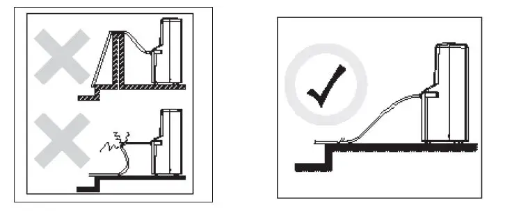
FAN MODE:
Note: During Fan Mode, the exhaust hose does not have to be vented outdoors.
- Press the POWER SWITCH button to turn the unit on.
- Press the MODE button until the FAN indicator illuminates on the control panel. Each press of the MODE button will advance to a different mode setting (Cool-Dehumidifi er-Fan-Heat)
- Press the FAN button to select the desired FAN SPEED setting. Your selection will appear on the control panel. Each press of the fan button will advance to a different fan speed (Low-Medium-High.)
HEAT MODE:
Note: During Heat Mode, the exhaust hose does not have to be vented outdoors.
- Press the POWER SWITCH button to switch on the unit, and the most recent set temperature will be shown in the temperature display area of the control panel.
- Press the MODE button until the heat indicator light illuminates on the control panel. Each depression of the MODE key will advance to a different mode setting (Cool-Dehumidify-Fan-Heat)
- Press the appropriate increase “+” or decrease “-” buttons to select a suitable operating temperature setting. Temperature settings are adjustable between 16°C (61°F) to 27°C (80°F.)
- Press the FAN button to select the desired fan speed setting (Low-Medium-High.) Your selection will appear on the control panel (each depression of the fan button will advance to the next setting.)
Note: Heating stops automatically when the set temperature is achieved. Heating resumes when the room temperature falls below the “set” temperature level.
AUTO-TIMER:
While the Air Conditioner is in Standby Mode (Auto-On):
- Press the Timer button once and the adjacent Auto-Timer display will illuminate.
- Use the Up/Down arrows to select a delayed On Time of up to 24 hours.
- Select the appropriate mode under which you want the unit to operate (Cool-Dehu-midify-Fan-Heat)
- Select the fan speed setting.
- The time you selected will appear in the LED display.
While the Air Conditioner is on (Auto-Off):
- Press the Timer button and the adjacent Auto-Timer display will illuminate.
- Use the Up/Down arrows to select a delayed Off Time of up to 24 hours.
- Follow the steps 3, 4, and 5 the same as above.
REMOTE CONTROL:
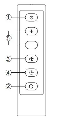
Control Buttons:
- Power
- Mode
- Fan Speed
- On/Off Timer
- Time/Temperature Set
The timer setting is programmable from 1 – 24 hours by fi rst pressing the On/Off Timer button and then the Time/Temperature Set buttons. When either the “+” or “-” button is pressed in cool mode, the set temperature is displayed and may be adjusted. After 15 seconds, the display will revert back to room temperature.Two AAA Alkaline batteries (S) (included) are required to operate the hand-held remote control.
Batteries should be replaced when:
- No signal (beep) is heard when attempting to program the main unit using the remote.
- The main unit does not respond to a command issued by the remote control.
- Gently slide the rear cover on the remote in the direction of the arrow until it separates completely from the unit.
- Insert two Alkaline AAA batteries (S) following the same orientation (polarity) depicted inside the battery chamber (+/-).
- Reinstall the rear cover.
- If the remote control will not be used for extended periods of time, the batteries should be removed.
Notes:
- Do not drop the remote control.
- Do not place the remote control in a location exposed to direct sunlight.
- Protect the remote control from high temperatures, and keep it away from radiation exposure.
- Keep the control panel receiver out of direct sunlight.
- If the remote control will not be used for extended periods of time (vacations, etc.), the batteries should be removed until they will be used again.
- Do not mix old and new batteries.
- Do not mix alkaline, standard (carbon-zinc) or rechargeable (Ni-Cd, Ni-MH, etc.) batteries.
- Do not attempt to recharge non-rechargeable batteries
- Dead batteries must be removed from the product and disposed of properly. Rechargeable batteries and batteries made before 1997 cannot be thrown away and must be recycled properly.
- This Class B digital apparatus complies with ICES-003.
- The remote operates within a range of 26 ft. from the receiver located inside the main unit. Any obstruction between the receiver and remote may cause signal interference, limiting the ability to program the main unit.
Note:
This equipment has been tested and found to comply with the limits for Class B digital device, pursuant to part 15 of the FCC Rules. These limits are designed to provide reasonable protection against harmful interference in a residential installation. This equipment generates, uses, and can radiate radio frequency energy and, if not installed and used in accordance with the instructions, may cause harmful interference to radio or television reception, which can be determined by turning the equipment off and on, the user is encouraged to try to correct the interference by one of more of the following measures.
- Reorient or relocate the receiving antenna.
- Increase the separation between the equipment and the receiver.
- Connect the equipment into an outlet on a circuit different from that to which the receiver is connected.
- Consult the dealer or an experienced radio/TV technician for assistance.
CAUTION:
Before cleaning or servicing this unit, disconnect from any electrical supply outlet.
- DO NOT use gasoline, benzene, thinner, or any other chemicals to clean this unit, as these substances may cause damage to the fi nish and deform plastic parts.
- NEVER attempt to clean the unit by pouring water directly over any of the surface areas, as this will cause deterioration of electrical components and wiring insulation.
- Always unplug the unit before servicing.
- Clean the unit by wiping off any dirt/dust with a soft damp cloth or vacuum cleaner, then wipe dry with a dry soft cloth.
CAUTION:
Always store the unit in vertical position. DO NOT put heavy objects on top of the unit.
CLEANING THE AIR FILTER:
CAUTION:
Never operate this unit without the air fi lter in place, as this may result in damage to the unit.
If the air fi lter becomes clogged with dust/dirt, air fl ow is restricted, which reduces cooling effi ciency. The air fi lter should be cleaned every two (2) weeks. More frequent cleaning may be necessary depending on indoor air quality.
NOTE:
The air fi lter is located at the upper rear side of the unit.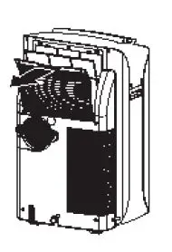
- To remove the air fi lter: Pull the air fi lter cover upward in the direction of the arrow and remove the air fi lter.
- Dust/dirt clogged in the fi lter can be removed by vacuum cleaning the soiled areas.
- The fi lter can also be washed in lukewarm, soapy water while rubbing it lightly with a brush. A mild detergent (such as dishwashing liquid) is recommended.
- Rinse the fi lter well using clean water. Allow time to dry before reinstalling into the unit.
- Replace the air fi lter and cover.
- Replacement air fi lter information is available by contacting the customer service department at 1-800-643-0067.
TROUBLESHOOTING
| PROBLEM | POSSIBLE CAUSE | CORRECTIVE ACTION |
|
Unit does not work. |
1. Power is out 2. Unit not plugged in properly 3. Water tank is full. STOP warning light will illuminate 4. Electrical current leaking or test button on LCDI plug is being pressed |
1. Wait for power to return 2. Plug in properly 3. Remove drain water from the drain tank (refer to page 9) 4. Press the reset button after resolving problem. |
|
Unit suddenly stops during operation. |
1. Indoor set temperature has been reached 2. The preset time is up 3. Water tank is full. STOP warning light will illuminate |
1. Reset the temperature level 2. Reset the timer 3. Remove drain water from drain tank (refer to page 9) |
|
Unit runs intermittently |
1. Malfunction 2. Surrounding temp. is more warm/ more cool than current heat/cool setting. 3. Exhaust duct hose is blocked |
1. Contact your dealer 2. This is normal. Unit doesn’t need to be operating constantly in this condition 3. Check and unblock the duct hose |
|
Unit functions but the room is not cooled. |
1. Window or door is open in room 2. There is a heat source or too many people in the room 3. Air intake grille is clogged 4. Filter is too dirty 5. Temperature setting is too high/warm |
1. Close all windows/doors 2. Move any heat sources from room 3. Clean air intake grille 4. Replace the filter 5. Lower the temp. setting |
|
Condensed water spills out when moving the unit. |
1. The water tank is nearly full |
1. Follow instructions on page 9 for draining water |
WARRANTY
LIMITED IN-HOME APPLIANCE WARRANTY
This product is warranted to be free from manufacturer’s defects in material and workmanship, provided that the unit is used under the normal operating conditions intended by the manufacturer. This warranty is available only to the person to whom the unit was originally sold by manufacturer or by an authorized distributor of manufacturer, and is non-transferable.
TERMS OF WARRANTY
Plastic parts, are warranted for thirty (30) days only from purchase date, with no extensions provided.
First 24 Months:
During the fi rst twenty four (24) months, any functional parts of this product found to be defective, will be repaired or replaced, at warrantor’s option, at no charge to the ORIGINAL purchaser. To obtain service: manufacturer reserves the right to limit the boundaries of “In Home Service” to the proximity of an Authorized Service Depot.
Service:
Manufacturer reserves the right to limit the boundaries of “In-Home Service” to the proximity of an Authorized Service Dealer. Any appliance requiring service outside the limited boundaries of “In Home Service”, it will be the consumer’s responsibility to transport the appliance (at their own expense) to the original retailer (point of purchase) or a service depot for repair. See “Boundaries of In Home Service” below. Contact your dealer from whom your unit was purchased, or contact your nearest authorized manufacturer service depot, where service must be performed by a qualifi ed service technician. If service is performed on the unit by anyone other than an authorized service depot, or the unit is used for commercial application, all obligations of manufacturer under this warranty shall be void.
Boundaries of In-Home Service:
If the appliance is installed in a location that is 62 miles or more from the nearest service center your unit must be delivered to the nearest authorized manufacturer Service Depot, as service must only be performed by a technician qualifi ed and certifi ed for warranty service by manufacturer. Transportation charges to and from the service location are not protected by this warranty and are the responsibility of the purchaser.
Nothing within this warranty shall imply that manufacturer will be responsible or liable for any spoilage or damage to food or other contents of this appliance, whether due to any defect of the appliance, or its use, whether proper or improper.
EXCLUSIONS
Save as herein provided, manufacturer, there are no other warranties, conditions, representations or guarantees, express or implied, made or intended by manufacturer or its authorized distributors and all other warranties, conditions, representations or guarantees, including any warranties, conditions, representations or guarantees under any Sale of Goods Act or like legislation or statue is hereby expressly excluded. Save as herein provided, manufacturer shall not be responsible for any damages to persons or property, including the unit itself, howsoever caused or any consequential damages arising from the malfunction of the unit and by the purchase of the unit, the purchaser does hereby agree to indemnify and hold harmless manufacturer from any claim for damages to persons or property caused by the unit.
GENERAL PROVISIONS
No warranty or insurance herein contained or set out shall apply when damage or repair is caused by any of the following:
- Power failure.
- Damage in transit or when moving the appliance.
- Improper power supply such as low voltage, defective house wiring or inadequate fuses.
- Accident, alteration, abuse or misuse of the appliance such as inadequate air circulation in the room or abnormal operating conditions (extremely high or low room temperature).
- Use for commercial or industrial purposes (ie. If the appliance is not installed in a domestic residence).
- Fire, water damage, theft, war, riot, hostility, acts of God such as hurricanes, fl oods, etc.
- Service calls resulting in customer education.
- Improper Installation (ie. Building-in of a free standing appliance or using an appliance outdoors that is not approved for outdoor application).Proof of purchase date will be required for warranty claims; so, please retain bills of sale. In the event warranty service is required, present this document to our AUTHORIZED SERVICE DEPOT.
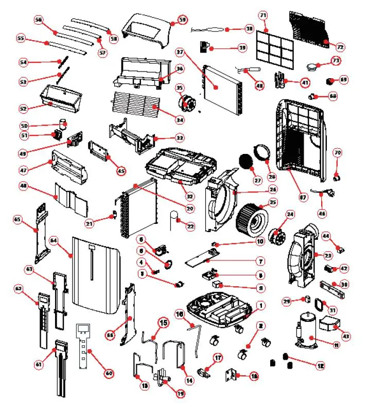
REPLACEMENT PARTS LIST
For replacement parts, call our customer service department at 1-800-643-0067, 8 a.m. – 6 p.m., EST, Monday – Thursday, 8 a.m. – 5 p.m., EST, Friday.
| PART DESCRIPTION PART # | ||
| 1 | BASE PAN | A4805-060-A-11 |
| 2 | CASTOR | A7402-020 |
| 3 | LOWER DRAIN PLUG | D7324-020 |
| 4 | STRIKE | A5802-440 |
| 5 | SPLASH MOTOR WT-15T1-03 | A3020-640 |
| 6 | SPLASH MOTOR BLADE | A5311-030-A-11 |
| 7 | SUMP COVER | A5408-070-H-11 |
| 8 | FLOAT HOUSING | A5405-010-H-11 |
| 9 | FLOAT | A5404-030 |
| 10 | FLOAT SWITCH | A2506-040 |
| 11 | COMPRESSOR ASSEMBLY | A3203-330 |
| 12 | GROMMETS | A5600-170 |
| 13 | DISCHARGE PIPE | A6209-660 |
| 14 | SUCTION PIPE | A6228-580 |
| 15 | CONNECTOR PIPE | A6214-270 |
| 16 | CONNECTOR PIPE | A6214-260 |
| 17 | RUBBER | A5600-140 |
| 18 | BRACKET | A5806-270 |
| 19 | REFRIGERATION VALVE ASSEMBLY | A7316-223 |
| 20 | CONDENSER ASSEMBLY | A3423-090 |
| 21 | Y TUBE | D6210-060 |
| 22 | CAPILLARY LINE | A6204-300 |
| 23 | EXHAUST MOTOR HOUSING A | A5301-340-AB-22 |
| 24 | EXHAUST MOTOR (LS-53T1-4P) | A3002-350 |
| 25 | EXHAUST BLOWER WHEEL | A5304-450-AH-11 |
| 26 | EXHAUST MOTOR HOUSING B | A5301-320-A-22 |
| 27 | EXHAUST SCREEN | A7204-170 |
| 28 | DISCHARGE GRILLE | A4239-370-H-22 |
| 29 | CAPACITOR (9UF/250V) FOR FAN MO-
TOR (24) | A2509-410 |
| 30 | FIXTURE | A5825-370-AF-11 |
| 31 | FIXTURE | A5825-350-AF-11 |
| 32 | EVAP TRAY | A5702-04A-A-22 |
| 33 | RECIRCULATING FAN HOUSING A | A5301-580-A-22 |
| 34 | EXHAUST BLOWER | A5308-030 |
| 35 | EXHAUST MOTOR (LS-16T3-02) | A3002-320 |
| 36 | RECIRCULATING FAN HOUSING B | A5301-570-A-22 |
| PART DESCRIPTION PART # | ||
| 37 | EVAPORATOR ASSEMBLY | A3419-830 |
| 38 | SENSOR (AMBIENT) | A2524-190 |
| 39 | SENSOR | A5812-540-P-11 |
| 40 | SENSOR (FOR EVAP) | A2524-240 |
| 41 | METAL FIXTURE | D5806-080 |
| 42 | TERMINAL BLOCK | A2525-130 |
| 43 | COVER | A6101-620-AF-11 |
| 44 | CAPACITOR 4UF/250V FOR MOTOR (35) | A2509-060 |
| 45 | FIXTURE | A5825-410-AF-11 |
| 46 | POWER SUPPLY CORD | A3702-370 |
| 47 | FIXTURE | A7700-120 |
| 48 | FIXTURE | A5708-070 |
| 49 | CONTROL BOARD | A2516-750 |
| 50 | CAPACITOR (55UF/300V) FOR COM-
PRESSOR (11) | A2510-240 |
| 51 | FIXTURE | A5825-360-AF-11 |
| 52 | AIR CHUTE | A4239-360-AH-22 |
| 53 | CENTER LOUVER BAR | A5805-610-A-22 |
| 54 | SIDE LOUVER BAR | A4251-750-PB-22 |
| 55 | LOWER LOUVER | A4244-410-A-C5 |
| 56 | 2ND LOUVER | A4244-420-A-C5 |
| 57 | 3RD LOUVER | A4244-430-A-C5 |
| 58 | TOP LOUVER | A4244-440-A-C5 |
| 59 | TOP COVER | A4206-630-A-C5 |
| 60 | TOUCH PAD | A2553-050 |
| 61 | DISPLAY HOUSING FRONT | A6105-200-A-AF |
| 62 | DISPLAY HOUSING MIDDLE | A5825-310-H-22 |
| 63 | DISPLAY HOUSING REAR | A5825-320-H-22 |
| 64 | FRONT PANEL | A4202-430-A-G |
| 65 | LEFT SIDE PANEL A | A4211-680-A-C5 |
| 66 | RIGHT SIDE PANEL B | A4211-690-A-C5 |
| 67 | REAR PANEL | A4220-270-A-G |
| 68 | RUBBER PLUG | D7324-030 |
| 69 | SCREW CAP | D7305-150-A-G |
| 70 | LOWER SOFT PLUG | A7305-010-A-22 |
| 71 | AIR FILTER | A7301-970-P-G |
| 72 | FILTER COVER | A4262-300-A-G |
| 73 | COVER | A7306-040-Y-C5 |
| PART DESCRIPTION PART # | ||
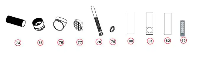
| 74 | HEAT EXHAUST HOSE | A6200-070 |
| 75 | HEAT EXHAUST HOSE CONNECTOR | A5815-090-H-BS |
| 76 | HEAT EXHAUST HOSE CONNECTOR | A5815-320-H-BS |
| 77 | EXHAUST GRILL COVER | A5812-210-H-BS |
| 78 | DRAINAGE PIPE | D7216-020 |
| 79 | WASHER | D3204-060 |
| 80 | WINDOW SLIDER KIT PIECE | A5700-390-V-BS |
| 81 | WINDOW SLIDER KIT PIECE | A5700-380-V-BS |
| 82 | WINDOW SLIDER KIT PIECE | A5700-400-V-BS |
| 83 | REMOTE CONTROL ASSEMBLY | A2530-450-AA09 |
Accessories

FAQS
Assuming you are in heading mode. You need to drain the water from the plugged drain line in the rear bottom of the unit. As odd as it seems, in heading mode, the unit extracts water from the air and when full without being drained, the unit shuts down. Try draining the water.
Water-cooled air conditioners must be hooked up to a water source because they contain a pool of water that is used to cool off hot air sucked from a room.
If your AC is blowing cold air out of the top vent, but your room still isn’t getting cold, your room is probably too hot or too large for the heat capacity of your air conditioner. Remember that portable air conditioners can only cool the room size they’re advertised for in moderate outdoor heat.
Mid-sized portable air conditioners use an average of 2900 watts per hour. Particularly large units can exceed the electricity usage of even central air conditioners, expending about 4100 watts per hour.
In high humidity areas, homeowners will have to drain the portable AC every few hours (2 to 8 hours, in general). In other areas, you have to drain the unit once per day or every few days.
Portable air conditioners last from 5 to 10 years. Portable AC units can be moved from room to room and can generate anywhere from 8,000 BTU to 15,000 BTU of cooling output. Portable AC units have the lowest lifespan of all AC types because: They get moved around a lot.
Portable air conditioners do not need regassing. Usually, air conditioner units are completely sealed; hence no gas leaves the unit. If it needs regassing, there is a clear indication of a leak. In that case, a professional should repair it.
Some disadvantages of portable air conditioners include heavy units that are difficult to move, high noise levels, draining the water regularly and the limited cooling space the unit offers.
No, not really. Out of all the various types of air conditioners available to homeowners, portable AC units are generally one of the worst in regard to energy efficiency.
All portable air conditioners produce condensation as they are cooled. This water is then contained in an internal water reservoir or drained through a hose. On all of our models, this water reservoir has an auto shutoff feature so that water is never accidentally spilled onto the ground.
The primary reason for your portable AC filling with water too quickly is humidity in the region you live. However excessive water deposit may also be due to dirty filter or clogged condensate line.
Air conditioners cannot cause carbon monoxide poisoning, because they do not burn fuel or produce carbon monoxide. It’s your heating equipment that you need to be concerned about.
Portable air conditioners don’t emit harmful gases. However, it is a must to vent the portable air conditioners so that hot air can discharge outside. Nevertheless, if you choose not to vent, it won’t cause any harm but reduce the cooling performance.
As long as one is breathing through the nose, it doesn’t matter. However if the nose is blocked due to allergy or viral infection, and the nose is unable to warm or humidify air going to the lungs , the child can develop cough because of dry , cold air going to the lungs .03-Aug-2016
Similarly, diastolic blood pressure (DBP) was higher with AC, 69.4 +/- 8.9 mmHg, than without AC, 66.5 +/- 9.1 mmHg, while mean blood pressure was also higher in AC, 84.9 +/- 9.1 mmHg, than without, 79.9 +/- 7.7 mmHg.
Once you have the right size air conditioner, there’s still an ideal temperature range to consider. It’s best to not set your thermostat lower than 70 to 72 degrees. Most units are not designed to cool a house below that point, and you risk the system freezing up.
Usually, blood pressure starts to rise a few hours before a person wakes up. It continues to rise during the day, peaking in midday. Blood pressure typically drops in the late afternoon and evening. Blood pressure is usually lower at night while sleeping.


