![]() Inspired iPower-DC2 AC-DC Power Adapter
Inspired iPower-DC2 AC-DC Power Adapter
User Manual
iPower-DC2 AC-DC Power Adapter
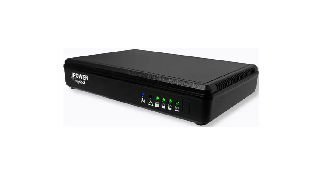
Thank you for selecting the Power Inspired iPower-DC² to protect your equipment. The iPower-DC² is an Uninterruptible Power System (UPS) providing battery backup power for DC products under 30W and operating from USB (10W max) or 9, 12 or 24Vdc. Ideal for small DC powered devices including but not limited to, network termination units, routers, hubs, IP cameras etc. It is intended to be installed between the equipment supplied DC power supply and the equipment.![]() Please read this manual before using the iPower-DC²
Please read this manual before using the iPower-DC²
⚠ Safety ⚠
Never expose the iPower-DC² to direct sunlight or sources of heat.
⚠ The iPower-DC 2 should only be used and stored in a dry indoor environment.
⚠ Ensure that the connected equipment is within the rating of the iPower-DC².
⚠ There are no user serviceable parts inside the iPower-DC² – do not open.
⚠ Do not use the product if the case is damaged.
⚠ The iPower-DC² contains batteries that must be processed according to local regulations.
☛ Precautions:
☛ Ensure that any AC/DC adapter used is regulated to within the voltage input specification of the iPower-DC², and an allowance of an additional 6W (0.67A@9V, 0.5A@12V, 0.25A@24V) is provided to cover the internal power consumption of the iPower-DC².
☛ The iPower-DC² will start up automatically when input power is applied.
☛ The input DC power source must match the setting on the voltage selector switch.
☛ In order to preserve battery longevity the iPower-DC² should be recharged as soon as possible following a power outage.
Package Contents:
- The iPower-DC² UPS
- User Manual
- 2x 5.5*2.1/2.5mm sprung connector DC male cables
Other optional accessories may be provided such as:
- DIN mounting kit
- AC/DC Power Adapter
- Lead adapter set
- Additional Leads (‘Y’-Cables or DC-DC leads)
Layout
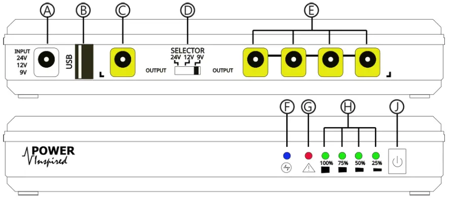
| Ⓐ DC Input Socket Ⓑ USB Output Ⓒ Primary DC Output Ⓓ Voltage Selector Switch Ⓔ Secondary DC Outputs | Ⓕ Set Voltage Indicator Ⓖ Warning / Fault Ⓗ Battery Status Indicators Ⓙ On/Off Switch |
Installation & Operation
- The iPower-DC² connects between the equipment DC supply and the equipment itself.
- Choose a suitable location out of direct sunlight and sources of heat with suitable access to the DC power supply and the connected equipment.
- Set the Voltage Selector Switch Ⓓ to match the required voltage.
- Note the polarity of both input and output DC jacks is centre pin positive

- Plug in the DC adapter or DC source into input socket Ⓐ and apply power.
- The iPower-DC² will automatically start up.
- Ensure the voltage indicator LED Ⓕ is indicating the correct voltage:
24V: RED
12V: BLUE
9V: PURPLE (RED & BLUE) - If the Voltage Indicator LED Ⓕ is flashing and the Fault LED Ⓖ is illuminated the input voltage does not match the voltage selector switch Ⓓ setting. Switch the unit OFF by disconnecting the input DC power source from Ⓐ and pressing and holding the Power Off button Ⓙ until all the LEDs extinguish (around 3 seconds). Set the selection switch to the correct voltage and repeat.
- Plug the equipment into the USB Ⓑ and/or DC output jacks Ⓒ Ⓔ as required using the DC male cables provided. For best performance the primary DC equipment should be connected to port Ⓒ. You can use USB and DC jack outlets at the same time provided the unit rating is not exceeded.
3.1. Battery Operation
- The iPower-DC² will immediately transfer to battery power if the input DC voltage is lost. There is no loss of power to connected equipment.
- When running on battery power the Voltage Indicator LED Ⓕ will flash and the green battery status indicator LEDs Ⓗ will show battery status:
⦿⦿⦿⦿ ⦾⦿⦿⦿ ⦾⦾⦿⦿ ⦾⦾⦾⦿ ⦾⦾⦾ 
75% → 100% 50% → 75% 25% → 50% 10% → 25% < 10% - NOTE: Due to the inherent discharge characteristics of Lithium batteries under varying load conditions, the battery status indicators are approximate. The unit is calibrated so that the reduction under same-load conditions from 25% to zero takes the longest time. At high loads, the battery status may drop from 100% to 75% quickly. This is normal.
3.2. Cold Starting (Powerbank operation)
- The iPower-DC² can be started up without DC input power by pressing and holding the ON/OFF switch Ⓙ until only the green battery LEDS Ⓗ illuminate (around 1-2 seconds). The Voltage Indicator LED Ⓕ will start to flash.
- NOTE: The output voltage when cold starting will be as per the voltage selector switch Ⓓ. Ensure this is correct before connecting any equipment.
3.3. Charging
- Following battery use, the iPower-DC² will start to recharge the internal battery as soon as DC input power is restored.
- The battery status indicator will flash when charging. Once full charge has been reached the LED indicators will be steady.
⦾⦾⦾ ⦾⦾ ⦿⦾ ⦿⦿⦿⦿⦿⦿⦿⦿⦿ <25% charge <50% charge <75% charge <100% charge Charged
3.4. Switching Off
- The iPower-DC² can only be switched off in battery mode.
- Disconnect the input DC source and press and hold the ON/OFF button Ⓙ until all LEDs are off (around 3-5 seconds).
3.5. Other
- If there is a voltage mismatch between input voltage (not including no-voltage) and the voltage setting on Ⓓ, then the fault LED Ⓖ will illuminate and the output power will be disconnected. This may occur when the voltage source is out of tolerance with the input specification of the iPower-DC² . Ensure the supply is regulated and within the power requirements of the equipment and the iPower-DC².
- If the voltage setting switch Ⓓ is changed whilst the unit is in operation the output will immediately be shut down and the fault LED Ⓖ will illuminate.
- In the event of an overload the fault LED Ⓖ will illuminate and the output will be shut off if the unit is operating from DC power. If the input voltage source allows for it, the iPower-DC² will start up once the fault has been removed. In battery mode the unit will shut off completely and will need to be restarted once the fault is removed.
Service
- Ensure the iPower-DC² is kept within normal operating and storage temperatures as specified in the specifications.
- Ensure the iPower-DC² is switched off when disconnected.
- Do not allow the iPower-DC² to remain for long periods with a discharged battery. Always recharge following battery use.
- The iPower-DC² will provide typically 5 years life in normal operating environments and does not require any ongoing maintenance.
- At end of life dispose of according to local battery and electronic equipment regulations.
Specifications
| Model | IPOWER-DC2 |
| INPUT 1 | |
| Voltage Input | 9V / 12V / 24Vdc |
| Range | 9V : 8.7~9.7Vdc |
| 12V: 11.6 ~ 13.1Vdc | |
| 24V: 23.2 ~ 25.4Vdc | |
| Maximum Input Capacity | 36W |
| OUTPUT | |
| Max Power | 30W |
| [Total – USB+Jacks] | |
| USB Port | |
| Interface | USB Type A |
| Voltage | 5V ±5% |
| Power Capacity | 2.0A / 10W |
| DC Output Jacks 2,3 | |
| Power Capacity | 30W |
| Voltage | 9Vdc / 12Vdc / 24Vdc (as per selector switch) |
| Range | 9V : 8.5~9.5Vdc |
| 12V: 11.4 ~ 12.6Vdc | |
| 24V: 22.8 ~ 25.2Vdc | |
| BATTERY | |
| Type | 18650 Lithium Ion |
| Capacity | 4x 2500mAh (2S2P) |
| Total Capacity | 37.0Wh / 10,000mAh (7.4V) |
| INDICATOR LEDS | |
| Battery Status | 4x Green LED indicating 25, 50, 75 & 100% charge |
| Flashing – Charging, @<10% discharging 25% LED flashes rapidly | |
| Voltage | 9V – Purple [Red/Blue], 12V – Blue, 24V – Red |
| Flashing indicates on battery power | |
| Red Fault LED | Overload / Voltage mismatch / Fault. |
| PROTECTION | |
| MCU | Overvoltage, overcharge, deep discharge, overload, short circuit, |
| over-temperature | |
| Battery | Over Charge, Over Discharge, Overload, short circuit |
| PHYSICAL & ENVIRONMENTAL | |
| Input Connection | 5.5×2.1mm DC Jack |
| Output | USB Type A |
| 5x 5.5×2.1mm DC Jack | |
| Dimensions (WxDxH mm) | 160x29x107mm |
| Weight (Gross / Net ) | 435/375g |
| Temperature | Operating 0-40 C Storage -10 – 45C |
| Humidity | 0-90% Non Condensing |
| Altitude | To 2000m |
| APPROVALS 4 | |
| UKCA / CE | BS EN 61204-1, BS EN 62477-1 |
| RoHS, EMC to BS EN 61204-3, | |
| Enclosure | ABS 94V0 |
| NOTES 1. A regulated DC power supply must be provided at the required output voltage and rated at 36W for full load rating. 2. The output voltage on the DC jacks is set by the selector switch and should match the nominal input voltage. 3. Applicable at primary jack port. 4. Product is exempt from Low Voltage Directive but designed in principle with safety and performance standards given. | |
![]() Ⓒ 2022 Power Inspired Ltd
Ⓒ 2022 Power Inspired Ltd
www.powerinspired.com
Rev 1.2


