VOLTA 5KWH 7.5KWH 10KWH Rechargeable Lithium User Manual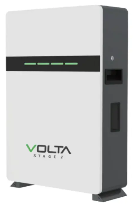
Statement of Law
Copyright of this document belongs to Solar Tech Wholesalers.
documentation maybe excerpted, reproduced, translated, annotated or duplicated in any form or by any means without the prior written permission of Solar Tech Wholesalers. All Rights Reserved.
This product complies with the design requirements of environmental protection and personal safety. The storage, use and disposal of the products shall be carried out in accordance with the product manual, relevant contract or relevant laws and regulations.
Customer can check the related information on the website of Solar Tech Wholesalers the product or technology is updated. Web URL: https://solartechwholesalers.co.za/
Please note that the product can be modified without prior notice.
Safety Precautions
![]() Warning
Warning
- Please do not put the battery into water or fire, in case of explosion or any other situation that might endanger your life.
- Please connect wires properly while installation, do not reverse connect. To avoid short circuit, please do not connect positive and negative poles with conductor (Wires for instance).
- Please do not stab, hit, trample or strike the battery in any other way.
- Please shut off the power completely when removing the device or reconnecting wires during the daily use or it could cause the danger of electric shock.
- Please use dry powder extinguisher to put out the flame when encountering a fire hazard, liquid extinguisher could result in the risk of secondary disaster.
- For your safety, please do not arbitrarily dismantle any component in any circumstances unless a specialist or an authorized one from our company, device breakdown due to improper operation will not be covered under warranty.
![]() Caution
Caution
- We have strict inspection to ensure the quality when products are shipped out, however, please contact us if case bulging or another abnormal phenomenon.
- For your safety, device shall be ground connected properly before normal use.
- To assure the proper use please make sure parameters among the relevant device are compatible.
- Please do not mixed-use batteries from different manufacturers, different types and models, as well as old and new together.
- Ambient and storage method could impact the life span and product reliability, please consider the operation environment abundantly to make sure device works in proper condition.
- For long-term storage, the battery should be recharged once every 6 months, and the amount of electric charge shall exceed 80% of the rated capacity.
- Please charge the battery in 18 hours after it discharges fully and starts over-discharging protection. Formula of theoretical standby time: T=C/I (T is standby time, C is battery capacity, I is total current of all loads).
Preface
Manual declaration
The VOLTA lithium iron phosphate battery energy storage system can provide energy storage solutions for photovoltaic power generation users through parallel combination. During the day, the excess power of photovoltaic power generation can be stored in the battery. At night or when needed, the stored electrical energy can be used to supply power to the electrical equipment, which can improve the efficiency of photovoltaic power generation, peak load shifting, and emergency power backup.
This user manual details the basic structure, parameters, basic procedures and methods of installation and operation and maintenance of the equipment.
Introduction
Brief Introduction
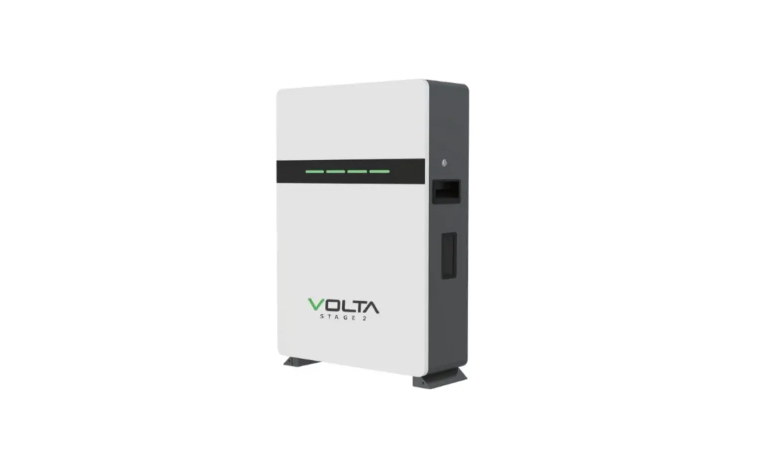
VOLTA lithium iron phosphate battery system is a standard battery system unit, customers can choose a certain number of VOLTA according to their needs, by connecting parallel to form a larger capacity battery pack, to meet the user’s long-term power supply needs. The product is especially suitable for applications with high operating temperatures, limited installation space, long power backup time and long service life.
Product Properties
VOLTA energy storage product’s anode materials are lithium iron phosphate, battery cells are managed effectively by BMS with better performance, the system’s features as below:
- Comply with European ROHS, Certified SGS, employ non-toxic, non-pollution environment-friendly battery.
- Anode materials are lithium iron phosphate (LiFePO4), safer with longer life span.
- Carries battery management system with better performance, possesses protection function like over-discharge, over-charge, over-current, abnormal temperature.
- Self-management on charging and discharging, Single core balancing function.
- Flexible configurations allow parallel of multi battery for longer standby time.
- Self-ventilation with lower system noise.
- Less battery self-discharge, then recharging period can be up to 10 months during the storage.
- No memory effect so that battery can be charged and discharged shallowly.
- With wide range of temperature for working environment, -20°C — +65°C, circulation span and discharging performance are well under high temperature.
- Less volume, lighter weight.
Product identity definition
![]()
Be careful with your actions and be aware of the dangers.

Read the user manual before using.

The scrapped battery cannot be put into the garbage can and must be professionally recycled.

After the battery life is terminated, the battery can continue to be used after it recycled by the professional recycling organization and do not discard it at will.

This battery product meetsEuropean directive requirements.

Battery voltage is higher than safe voltage, direct contact with electric shock hazard.
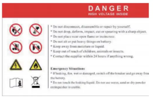
Dangerous goods warning label on the top of the battery module.
Product Specification
Size and Weight
Table 24 VOLTA Device size
| Product | NominalVoltage | NominalCapacity | Dimension | Weight |
| VOLTA STAGE 1 | DC51.2V | 100Ah | 480x600x150mm | z47kg |
| VOLTA STAGE 2 | DC51.2V | 150Ah | 480x650x180mm | t75kg |
| VOLTA STAGE 3 | DC51.2V | 202Ah | 480x650x225mm | :–95kg |
Performance Parameter
Table 2-2 VOLTA performance parameter
| Item Nominal Voltage(V) | Parameter value 51.2 | 1 Parameter value | Parameter value 51.2 |
| 51.2 | |||
| Work Voltage Range(V) | 44.856 | 44.856 | 44.8–56 |
| Nominal Capacity(Ah) | 100 | 150 | 202 |
| Nominal Energy(kWh) | 5.12 | 7.68 | 10.34 |
| C Rating | 1.0 | 1.0 | 0.75 |
| Charge Voltage(V) | 55.2-56 | 55.2-56 | 55.2-56 |
| Discharge Cutoff Voltage(V) | 44.8 | 44.8 | 44.8 |
| Equilized Charge Voltage(V) | 56 | 56 | 56 |
| Max. Continuous Charging Current(A) | 100 | 150 | 150 |
| Max. Continuous Discharging Current(A) | 100 | 150 | 150 |
Interface Definition
This section elaborates on interface functions of the front interface of the device.
Top View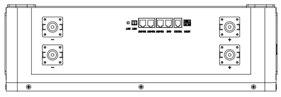
Table 2-3 interface Definition
| Item | Name | Definition |
| 1 | Power switch | OFF/ON,must be in the “ON” state when in use |
| 2 | DRY CONTACT | / |
| 3 | Reset | Restart all battery settings |
| 4 | ADD | DIP switch |
| 5 | RS485 | Communication cascade port, support RS485 communication |
| 6 | CAN | Communication cascade port, support CAN communication (factory default CAN communication) |
| 7 | RS232 | Communication cascade port,battery connect to the host computer |
| 8 | Parallell Parallell | Battery parallel connection ports |
| 9 | Positive socket | Battery output positive or parallel positive line |
| 10 | Negative socket | Battery output negative or parallel negative line |
DIP switch definition and description
Table 2-4 Interface Definition
| DIP switch position(host communication protocol and baud rate selection) | |||
| #1 | #2 | #3 | #4 |
| Baud rate selection | |||
| ON | OFF | ||
| CAN: 2501c485: 9600 | CAN: 500K,485: 9600 | ||
DIP switch description:
When the battery pack is connected in parallel, the host can communicate with the slave through the CAN interface. The host summarizes the information of the entire battery system and communicates with the inverter through CAN or 485. The connection mode is divided into the following two cases:

| Address | Codes the switch position | |||
| #1 | #2 | #3 | #4 | |
| 1 | OFF | OFF | OFF | OFF |
| 2 | ON | OFF | OFF | OFF |
| 3 | OFF | ON | OFF | OFF |
| 4 | ON | ON | OFF | OFF |
| 5 | OFF | OFF | ON | OFF |
| 6 | ON | OFF | ON | OFF |
| 7 | OFF | ON | ON | OFF |
| 8 | ON | ON | ON | OFF |
| 9 | OFF | OFF | OFF | ON |
| 10 | ON | OFF | OFF | ON |
| 11 | OFF | ON | OFF | ON |
| 12 | ON | ON | OFF | ON |
| 13 | OFF | OFF | ON | ON |
| 14 | ON | OFF | ON | ON |
| 15 | OFF | ON | ON | ON |
| 16 | ON | ON | ON | ON |
Table 5 Dial switch position
Table 2-4 Pin Definition
RS485-1/CAN Communication Interface Definition:
| Interface | Defined declaration | Defined declaration | ||||
| X1 Communication port definition | A partCAN joggle | PIN 1 | CANL | B part RS-485-1 Interface | PIN 1 | RS485-B1 |
| PIN 2 | CGND | PIN 2 | RS485-A1 | |||
| PIN 3 | NC(empty) | PIN 3 | RS485-GND | |||
| PIN 4 | CANH | PIN 4 | RS485-B1 | |||
| PIN | CANL | PIN 5 | RS485-A1 | |||
| PIN 6 | NC(empty) | PIN 6 | RS485-GND | |||
| PIN 7 | CGND | PIN 7 | NC(empty) | |||
| PIN 8 | CANH | PIN 8 | NC(empty) | |||
Table 7 The RS 485-1 / CAN port definition
Table 2-5 LED status indicators
| State | Normal / alarm 1 protection | RUN | ALM | The power level indicates the LED | Explain | ||||
| Shut down | Dormancy | off | off | off | off | off | off | All off | |
| Standby | Normal | Flash 1 | off | According to the electricity instruction | Stand by | ||||
| Alarm | Flash 1 | Flash 3 | Module low voltage | ||||||
| Charge | Normal | Lighting | off | According to the electricity instruction (Power level indicates maximum LED flash 2) | Alarm when overvoltage light off | ||||
| Alarm | Lighting | Flash 3 | |||||||
| Overcharge protection | Lighting | off | Lighting | Lighting | Lighting | Lighting | If there is no charging, the indicator light is in standby state | ||
| Temperature. overcurrent, protection | off | Lighting | off | off | off | off | Stop charging | ||
| Discharge | Normal | Flash 3 | off | According to the electricity instruction | |||||
| Alarm | Flash 3 | Flash 3 | |||||||
| Undervoltage protection | off | off | off | off | off | off | Stop discharge | ||
| Temperature, over- current, short-circuit. Reverse connection and failure protection | off | Lighting | off | off | off | off | Stop discharge | ||
| Fail | off | Lighting | off | off | off | off | Stop charging and discharging | ||
Table 1 LEDF working status Indication
| State | Charge | Discharge | |||||||
| Capacity indicator light | L4 | L3 | L2 | L 1 | L4 | L3 | L2 | L 1 | |
| Battery Power(%) | 0 – 25%25 – 50%50 – 75% | off | off | off | Fla2sh | off | off | off | Lighting |
| off | off | Fla2sh | Lighting | off | off | Lighting | Lighting | ||
| off | Flash2 | Lighting | Lighting | off | Lighting | Lighting | Lighting | ||
| 75 – 100% | Flash2 | Lighting | Lighting | Lighting | Lighting | Lighting | Lighting | Lighting | |
Table 2 Capacity indication Instruction
| Flash mode | Bright | off |
| Flash. 1 | 0.25S | 3.75S |
| Flash. 2 | 0.5S | 0.5S |
| Flash. 3 | 0.5S | 1,5S |
Battery Management System(BMS)
Voltage Protection
Discharging Low Voltage Protection :
When any battery cell voltage is lower than the protection value during discharging, The over-discharging protection starts, and the battery buzzer makes an alarm sound. Then battery system stops supplying power to the outside. When the voltage of each cell recovers to rated return range, the protection is over.
Charging Over Voltage Protection:
When total voltage or any battery cell voltage reaches the protection value during charging, battery stops charging. When total voltage or a cell recover to rated return range, the protection is over.
Current Protection
Over Current Protection in Charging:
When the charging current is greater than the protection value, the battery buzzer alarms and the system stops charging. Protection is removed after rated time delaying.
Over Current Protection in Discharging:
When the discharge current is greater than the protection value, the battery buzzer alarms and the system stops discharging. Protection is released after rated time delaying.
![]() Note: The buzzer sound alarm setting can be manually turned off on the background software, and the factory default is on.
Note: The buzzer sound alarm setting can be manually turned off on the background software, and the factory default is on.
Temperature Protection
Less/Over temperature protection in charging:
When battery’s temperature is beyond range of 0 C -+65 C during charging, temperature protection starts, device stops charging. The protection is over when it recovers to rated return range.
Less/Over temperature protection in discharging:
When battery’s temperature is beyond range of -20 C’+65 C during discharging, temperature protection starts, device stops supplying power to the outside.
Installation and Configuration
Ready for installation
Safety Requirement
This system can only be installed by personnel who have been trained in the power supply systen and have sufficient knowledge of the power system. The safety regulations and local safety regulations listed below should always be followed durin€ the installation.
- All circuits connected to this power system with an external voltage of less than 48\ must meet the SELV requirements defined in the IEC60950 standard.
- If operating within the power system cabinet, make sure the power system is nol charged. Battery devices should also be switched off.
- Distribution cable wiring should be reasonable and has the protective measures tc avoid touching these cables while operating power equipment.
- when installing the battery system, must wear the protective items below:

The isolation gloves
Safety goggles
Safety shoes
Figure 3-1
Environmental requirements
Working temperature: -20 °C — +55 °C
- Charging temperature range is 0°C—+55 °C,
- Discharging temperature range is -20 °C “+55 °C
Storage temperature: -10 °C – +35°C
Relative humidity: 5% — 85%RH
Elevation: no more than 4000m
Operating environment: Indoor installation, sites avoid the sun and no wind, no conductive dust and corrosive gas.
And the following conditions are met:
- Installation location should be away from the sea to avoid brine and high humidity environment.
- The ground is flat and level.
- There is no flammable explosive near to the installation places.
- The optimal ambient temperature is 15°C — 30 °C
- Keep away from dust and messy zones 3.1.2 Tools and data Hardware tool Tools and meters that may be used are shown in table 3-1. Table 3-1 Tool instrument
| Name | |||
| Screwdriver (word, cross) | AVO meter | ||
| Wrench | Clamp meter | ||
| Inclined pliers | Insulating tape | ||
| Needle nose pliers | The thermometer | ||
| Clip forceps | Wrist strap | ||
| Wire stripper | AVO meter | ||
| Electric drill | Tape | ||
Technical preparation
Electrical interface check
Devices that can be connected directly to the battery can be user equipment, power supplies, or other power supplies.
- Confirm whether the users PV power generation equipment, power supply or other power supply equipment has a DC output interface, and measure whether the DC power output voltage meets the voltage range requirements in Table 2-2.
- Confirm that the maximum discharge current capability of the DC power interface of the users photovoltaic power generation equipment, power supply or other power supply equipment should be greater than the maximum charging current of the products used in Table 2-2. If the maximum discharge capacity of the DC power interface of the user’s photovoltaic power generation equipment is less than the maximum charging current of the products used in Table 2-2, the DC power interface of the user’s photovoltaic power generation equipment shall have a current limiting function to ensure the normal operation of the user’s equipment.
- Verify that the maximum operating current of the battery-powered user equipment (inverter DC input) should be less than the maximum discharge current of the products used in Table 2-2.
The security check - Firefighting equipment should be provided near the equipment, such as portable dry powder fire extinguisher.
- Automatic fire fighting system shall be provided for the case where necessary.
- No flammable, explosive and other dangerous articles are placed beside the battery.
Unpacking inspection
- When the equipment arrives at the installation site, loading and unloading should be carried out according to the rules and regulations, to prevent from being exposed to sun and rain.
- Before unpacking, the total number of packages shall be indicated according to the shipping list attached to each package, and the case shall be checked for good condition.
- In the process of unpacking, handle with care and protect the surface coating of the object.
- Open the package, the installation personnel should read the technical documents, verify the list, according to the configuration table and packing list, ensure objects are complete and intact, if the internal packing is damaged, should be examined and recorded in detail.
Engineering coordination
Attention should be paid to the following items before construction:
- Power line specification. The power line specification shall meet the requirements of maximum discharge current for each product.
- Mounting space and bearing capacity. Make sure that the battery has enough room to install, and that the battery rack and bracket have enough load capacity
- Wiring. Make sure the power line and ground wire are reasonable. Not easy to short-circuit, water and corrosion.
3.2 Equipment installation
Installation steps
Table 3-2 Installation steps
| Step 1 | Installation preparation | Confirm that the ON/OFF switch on the front panel of unit is in the “OFF” state to ensure no live operation. |
| Step 2 | Mechanical installation |
|
| Step 3 | Electrical installation |
|
| Step 4 | Battery system self-test |
|
| Step 5 | Connecting inverter |
|
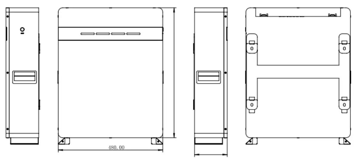
Product Size:
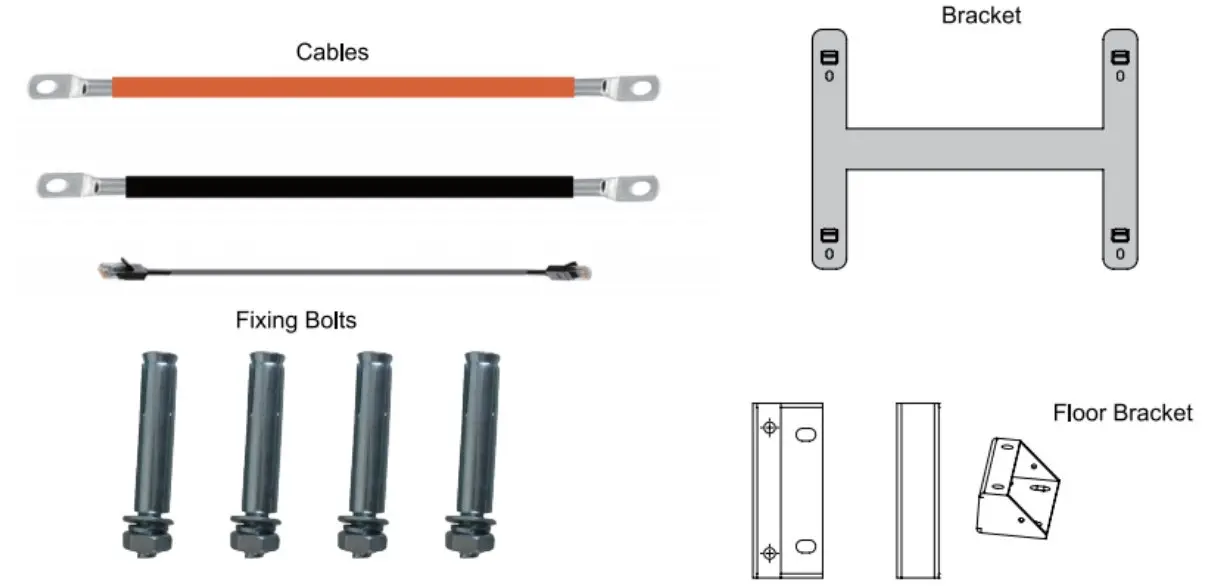
Accessories; (Optional)
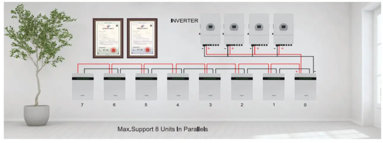
Parallel Connection Of Batteries
Connect the positive pole and positive pole in parallel, and the negative pole and negative pole in parallel. as shown in the figure below
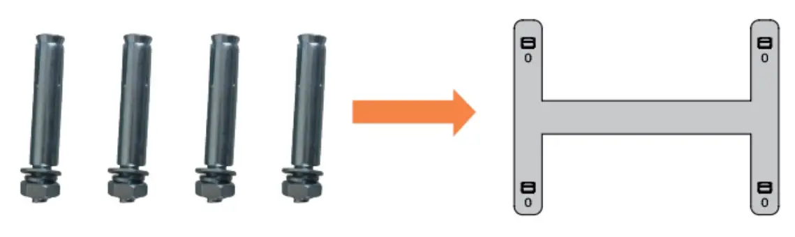
Installation Notes
- As shown in the figure below, press the fixed pendant on the wall surface with one hand, use a marker to draw the installation positioning hole of the fixed pendant, and use a tool to drill.

- As shown in the figu e below, fix the attached 4 M8 expansion bolts in the opening of the pendant, and tighten the nuts on the bolts.

- Lift up the 51.2V battery box, adjust the opening of the pendant on the back of the box to align with the pendant on the wall as shown in the figure below, and then use a marker to mark the mounting ears of the box, and use tools to drill holes for the mounting ears.

Wall Mount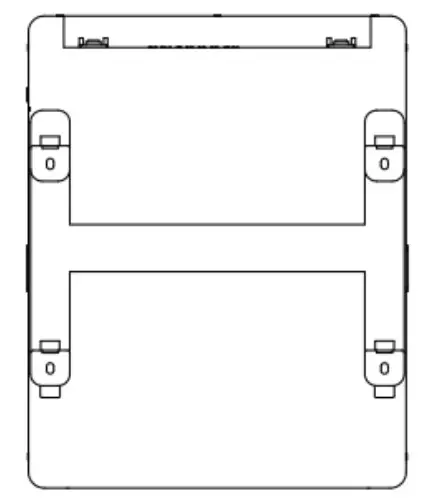
Floor Mount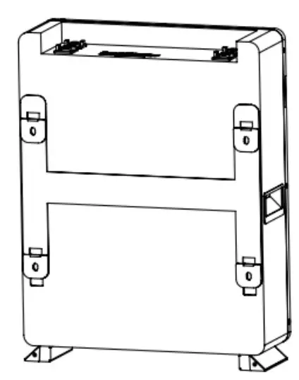
Communicate inverter
Method 1:Communicate factory default inverters
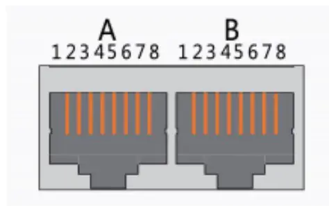
Step 1:Select the cables used by the inverter by the label on the communication cables.lnsert the 8145 connector of the battery end(CAN/RS485) and the inverter end(CAN/RS485) into the interfaces on both sides.
Step 2:Turn on the battery and inverter and wait until they are working properly. The battery is configured by factory default to communicate with the Voltronics,Mecer,Kodak,Phocos,Axpert Inverter (R5485 Port ) , DEYE, Sunsynk, SMK(Hybrid),Luxpower,Sofar, TBB inverters (CAN Port), the battery will automatically select and communicate with one of these inverters.
Step 3:After successful communication between battery and inverter, battery status will be displayed on inverter: voltage,current,SOC, temperature, etc.
Method 2:Communicate optional inverters(protocol select)
When communicating with other brands of inverters,suchas:Growatt,Solax,Goodwe,Sorotech,LTW,MUST,SMA,etc.
Step 1:Turn on the battery,ensure BMS is normally powered on and not in sleep state, the RS232 crystal head of the communication cable is inserted into the battery communication port, the USB end is inserted into the computer;
Step 2:Unzip the package of BMS monitoring software to the current computer( Windows Microsoft NET Framework 2.0 or above). This software does not need to be installed independently, only the environment is satisfied, double-click the main program icon(BMS exe file) to run and use. Enter the password:green1234 (space is green, the password is correct).
Step 3: Click “Parameter information”at the top of system page, click”Read”button to read battery parameter.Select the inverter protocol at “Protocol type”.Click the “Write”button to set the protocol,after the system displays the operation succeeds, protocol selection is complete(Please refer to the following pictures).
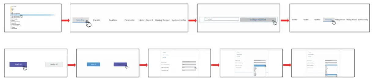
Step 4:Select the cables used by the inverter by the label on the communication cables.lnsert the RJ45 connector of the battery end(CAN/RS485) and the inverter end(CAN/RS485) into the interfaces on both sides. Restart the battery and inverter. The battery will automatically communicate with the inverter corresponding to the selected protocol.
Remark of inverter protocol code
Inverter protocol code remark
| RS485 Protocol | ||
| Protocol Code | Inverter brand | Compatible(Same protocol) |
| Darfon | Voltronic Power | MOTOMA/Opti Solar/Victron |
| Growatt | Growatt | |
| ESENER | 1SLNER(off-grid) | |
| SOLAX | SOLAX Power | |
| LTW | Lt-power | |
| SRNE | SRNE Solar | PACE/Epever |
| PV3500 | MUST Solar | |
| CAN Protocol | ||
| Protocol Code | Inverter brand | Compatible(Same protocol) |
| GOODWE | GOODWE | SOLARFAM |
| PYLONTECH | PYLONTECH | DEYE/Sunsynk/LUXPower/TBB/SOFAR/ESENER(hybrid) |
| SOROTEC | SORO Power | Victron/SMA |
| SOLAX | SOLAX Power | |
| PV1800F | MUST Solar | |
| LTW | Lt•power | |
| Growatt | Growatt | |
| Schneider | Schneider Electric | |