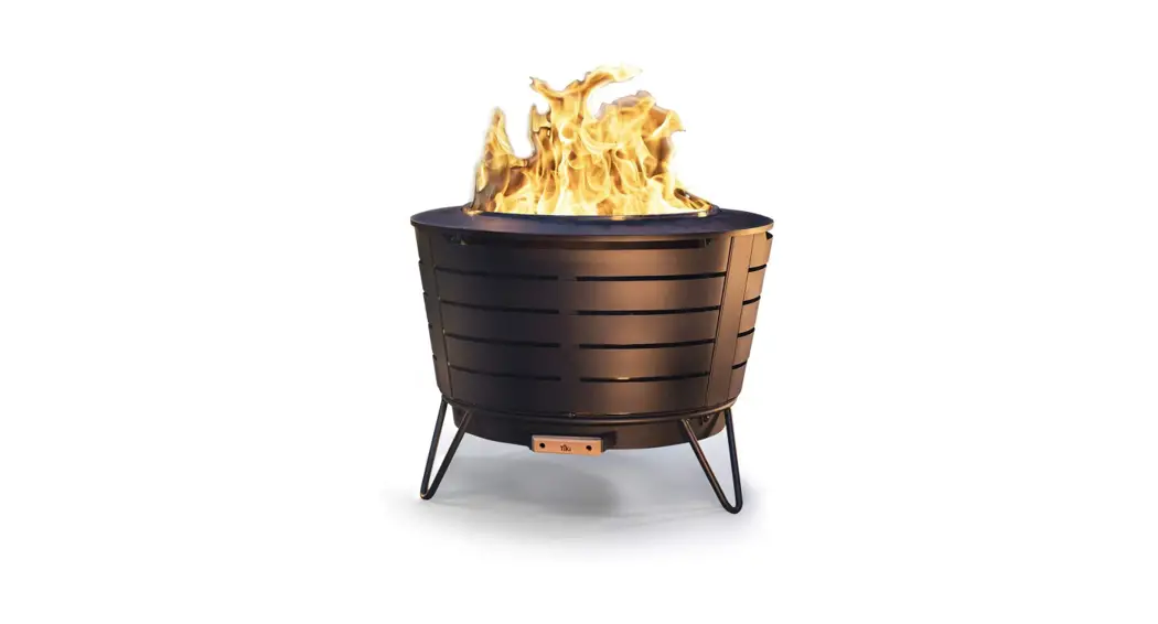
![]() FIREPOT / FIRE TABLE
FIREPOT / FIRE TABLE
INSTALLATION INSTRUCTIONS – AUTO IGNITION
SAVE THESE INSTRUCTIONS FOR FUTURE REFERENCE
 Scan with your phone for Step by Step instructions, or visit www.c-m-p.com/tech
https://scnv.io/pIT9?qr=1
IMPORTANT SAFETY INFORMATION: READ AND FOLLOW ALL INSTRUCTIONS
Save these instructions. Leave manual with the homeowner after installation.
Improper installation, adjustment, alteration, service, or lack of maintenance can cause injury or property damage. Read the installation, operating, & maintenance instructions thoroughly before installing or servicing this equipment.
IMPORTANT WARNINGS & SAFETY INSTRUCTIONS
READ AND FOLLOW ALL INSTRUCTIONS
![]() WARNING Do not store or use gasoline or flammable vapors and liquids in the vicinity of this appliance. Do not install this appliance near any combustibles. A Liquid Propane cylinder not connected for use shall not be stored in the vicinity of this or any other appliance.
WARNING Do not store or use gasoline or flammable vapors and liquids in the vicinity of this appliance. Do not install this appliance near any combustibles. A Liquid Propane cylinder not connected for use shall not be stored in the vicinity of this or any other appliance.![]() WARNING RISK OF SHOCK OR ELECTROCUTION. Hazardous voltage can shock, burn and cause death or serious property damage.
WARNING RISK OF SHOCK OR ELECTROCUTION. Hazardous voltage can shock, burn and cause death or serious property damage.![]() WARNING Installation must be performed by a licensed professional. Improper installation, adjustment, alteration, service, or maintenance can cause injury or property damage. The installer must follow all local codes as well as National Fuel Gas Code, ANSI Z223.1.
WARNING Installation must be performed by a licensed professional. Improper installation, adjustment, alteration, service, or maintenance can cause injury or property damage. The installer must follow all local codes as well as National Fuel Gas Code, ANSI Z223.1.![]() WARNING This product must be installed by a licensed or certified electrician or a qualified pool professional in accordance with the National Electric Code (NEC) or Canadian Electric Code (CEC), CSA C22.1.
WARNING This product must be installed by a licensed or certified electrician or a qualified pool professional in accordance with the National Electric Code (NEC) or Canadian Electric Code (CEC), CSA C22.1.![]() WARNING Turn off power to controls before installation/service. Failure to comply will either damage or destroy the product and will void the warranty.
WARNING Turn off power to controls before installation/service. Failure to comply will either damage or destroy the product and will void the warranty.![]() WARNING To reduce the risk of injury, do not permit children to use this product.
WARNING To reduce the risk of injury, do not permit children to use this product.![]() CAUTION If you smell gas, shut off the gas to the appliance and extinguish any open flame. If the odor lingers keep away from the appliance and immediately call the gas supplier or fire department. Do not leave any flame unsupervised.
CAUTION If you smell gas, shut off the gas to the appliance and extinguish any open flame. If the odor lingers keep away from the appliance and immediately call the gas supplier or fire department. Do not leave any flame unsupervised.![]() CAUTION Gas pressure should not exceed 1/2 psi.
CAUTION Gas pressure should not exceed 1/2 psi.![]() DANGER Carbon Monoxide Hazard: This appliance can produce carbon monoxide which has no odor. Using it in an enclosed space can cause serious injury or death. Never use this appliance in an enclosed space such as a camper, tent, car, or home.
DANGER Carbon Monoxide Hazard: This appliance can produce carbon monoxide which has no odor. Using it in an enclosed space can cause serious injury or death. Never use this appliance in an enclosed space such as a camper, tent, car, or home.![]() CAUTION HOT! DO NOT TOUCH. SEVERE BURNS MAY RESULT. CLOTHING IGNITION MAY RESULT.
CAUTION HOT! DO NOT TOUCH. SEVERE BURNS MAY RESULT. CLOTHING IGNITION MAY RESULT.
Glass and other surfaces are hot during operation and cool-down. CAREFULLY SUPERVISE children near this appliance. Alert children and adults to hazards of high temperatures.
SAVE THESE INSTRUCTIONS
ADHERE TO ALL LOCAL CODES CONCERNING INSTALLATION AND OPERATION.
- For outdoor use only.
- The product is not intended to be a starter for wood or any other combustibles.
- Test for gas leaks prior to use.
- Verify correct gas fuel type. Never use an alternative fuel, including bio-fuel, ethanol, lighter fluid or any other fuel.
- Installation must be performed by licensed gas piping professional.
- When a product is not in use for an extended period, turn off gas to prevent unwanted start-up.
- The use of a cover when not in operation is recommended.
- Verify gas shut-off is located outside of the product or column. The gas shutoff should NOT be used to adjust the flame height.
- An approved gas valve or keyed valve shall be installed upstream of the unit and located in an accessible area that is
within 5ft from the unit.
![]() WARNING Do not modify units from factory configuration. Doing so will void the warranty.
WARNING Do not modify units from factory configuration. Doing so will void the warranty.
NOTICE The manufacturer is not responsible for damage due to improper installation.
SYSTEM REQUIREMENTS
Installation must be performed by a licensed contractor. The installer must follow all local codes as well as National Fuel Gas Code, ANSI Z223.1. We suggest that our products be serviced annually by a professional certified in the US by the National
Fireplace Institute (NFI) as NFI Gas Specialists or in Canada by WETT (Wood Energy Technical Training). The installer must follow all instructions carefully to ensure proper performance and safety.
NOTICE This product is for outdoor use only.
PERFECT FLAME™ FIRE RING
| BURNER SIZE | BTUS (IN K’S) |
| FIRE RING – 9” | 50 |
| FIRE RING -16” | 120 |
| FIRE RING -22” | 175 |
| FIRE RING -29” | 230 |
| FIRE RING -35” | 240 |
| FIRE RING -42” | 270 |
PERFECT FLAME™ FIRE LINE
| BURNER SIZE | BTUS (IN K’S) |
| FIRELINE -24” | 40 |
| FIRELINE -29” | 50 |
| FIRELINE -35” | 55 |
| FIRELINE -48” | 70 |
| FIRELINE -61” | 80 |
| FIRELINE -74” | 85 |
| FIRELINE -87” | 95 |
| FIRELINE -100” | 105 |
| FIRELINE -113” | 115 |
| FIRELINE -126” | 150 |
| FIRELINE -134” | 175 |
| FIRELINE -146” | 185 |
REQUIRED GAS PRESSURE
| DESCRIPTION | WATER COLUMN |
| LIQUID PROPANE | 10″ WC |
| NATURAL GAS | 3.5″ WC |
Input pressure should not exceed 1/2 psi
Note: check with your gas supplier to verify gas flows and pressures available at the location of your installation. In many cases utility companies will install larger meters at no charge to accommodate larger flows.
ELECTRICAL REQUIREMENTS
- Autoignition requires 12 VAC
- The included transformer steps down from 120 VAC to 12VAC
- The installer should check the voltage after installation to ensure proper values
- In the United States the National Electrical Code® (NEC®) and in Canada the Canadian Electrical Code (CEC), require that all metallic components of a pool structure, including reinforcing steel, metal fittings, and above-ground components be bonded together (forming an equipotential bonding grid) with a solid copper conductor not smaller than an 8 AWG (6 AWG in Canada).
- To prevent premature failure of the appliance resulting from stray voltages and voltage differentials, the burner must be bonded to other equipment which is part of the pool plumbing system with a solid copper wire not smaller in diameter than 8 AWG (6 AWG in Canada).
- The National Electrical Code® (NEC) allows listed low-voltage gas-fired luminaires, decorative fireplaces, fire pits, and similar equipment using low voltage igniters that do not require grounding and are supplied by a listed transformer/power supply with outputs that do not exceed the low-voltage contact limit (15 V RMS ac, 30 V continuous DC) to be permitted to be located less that 1.5m (5ft) from the inside walls of the pool.
- Metallic equipment, including metallic gas piping, shall be bonded in accordance with the NEC in the US, and the Canadian Electrical Code (CEC) in Canada.
- In the NEC and CEC require that all metallic components of a pool structure, including reinforcing steel, metal fittings and
above ground, components be bonded together (forming an equipotential bonding grid) with a solid copper conductor not smaller than an 8 AWG (6 AWG in Canada)
FIREPOT/TABLE INSTALLATION
LOCATION
DRAINAGE
- Firepot/tables should have adequate drainage for rainwater. Select a location with adequate drainage. Install above grade to prevent water retention.
ACCESS
- Leave easy adequate access for installation and maintenance.
- To safely turn off the burner, you must have clear and easy access to the ON / OFF valve AFTER the appliance is connected to the gas supply.
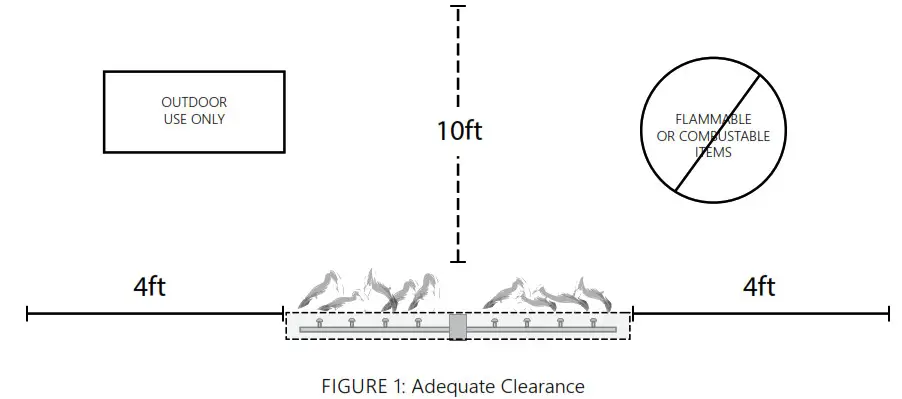
CLEARANCE
- Recommended Clearances: Sides 4 ft / Top 10 ft: Combustibles/structures not to be closer than 4’ on the horizontal plane, 10’ overhead. (FIG 1).
- No combustible structure should be above the fire feature.
- Do not completely enclose. No more than two side structures should be around the fire feature.
- Do not recess the fire feature below ground/floor level.
- Natural stone such as granite or marble must be kept away from heat and flame. Contact and close proximity can result in cracking or explosion.
- Install fire features out of the way of pedestrian traffic. Provide space to allow a safe distance from the heat and flame.
- Vent collars and drainage should never be obstructed.
SETUP
DRAINAGE
- For natural gas only, a dedicated drain line may be installed under the pot/table.
- Installations using propane should not have drains located below the unit. Drainage should be achieved with vent holes in the product and/or around the column.
VENTING
- WARNING: All installations must have proper ventilation around and under the unit to allow possible accumulated gas to escape. Failure to do so may cause a dangerous build-up of gas and can explode.
- The ventilation location must be such that any settled gas can escape.
- Vents are pre-installed in the fire pot and table. If installing on an open column or pedestal, ventilation must be added to prevent dangerous gas build-up.
FIREPOT/TABLE INSTALLATION
- The top of a column or pedestal on which fire feature is installed should be sealed around.
- A minimum of two vents on opposing sides of a column are required. See Table 1 for minimum vent requirements.
Multiple vents evenly spaced totaling minimum requirement or more is also acceptable. Minimum air openings shall not be less than 3 inches. - One vent should be within 12 inches of the bottom of the column and another within 12 inches from the top of the column.
- Vents should not be blocked from air circulation.
VENTILATION OPENING SIZE
| BURNER SIZE | BTUS (IN K’S) | MINIMUM VENT SIZE (EACH – TWO REQUIRED) |
| FIRE RING -9” | 50 | 12.5in2 |
| FIRE RING -16” | 120 | 30in2 |
| FIRE RING -22” | 175 | 43.8in2 |
| FIRE RING -29” | 230 | 57.5in2 |
| FIRE RING -35” | 240 | 60in2 |
| FIRE RING -42” | 270 | 67.5in2 |
| FIRELINE -24” | 40 | 10in2 |
| FIRELINE -29” | 50 | 12.5in2 |
| FIRELINE -35” | 55 | 13.8in2 |
| FIRELINE -48” | 70 | 17.5in2 |
| FIRELINE -61” | 80 | 20in2 |
| FIRELINE -74” | 85 | 21.3in2 |
| FIRELINE -87” | 95 | 23.8in2 |
| FIRELINE -100” | 105 | 26.3in2 |
| FIRELINE -113” | 115 | 28.8in2 |
| FIRELINE -126” | 150 | 37.5in2 |
| FIRELINE -134” | 175 | 43.8in2 |
| FIRELINE -146” | 185 | 46.3in2 |
AIR MIXER FOR PROPANE UNITS
| BURNER SIZE | AIR MIXER P/N | AIR MIXER BTUS |
| FIRE RING -9” | 8-1392-01 | 50K |
| FIRE RING -16” | 8-1450-01 | 120K |
| FIRE RING -22” | 8-1451-01 | 175K |
| FIRE RING -29” | 8-1453-01 | 240K |
| FIRE RING -35” | ||
| FIRE RING -42” | 8-1454-01 | 270K |
| FIRELINE -24” | 8-1392-01 | 50K |
| FIRELINE -29” | ||
| FIRELINE -35” | ||
| FIRELINE -48” | 8-1459-01 | 85K |
| FIRELINE -61” | ||
| FIRELINE -74” | ||
| FIRELINE -87” | 8-1450-01 | 120K |
| FIRELINE -100” | ||
| FIRELINE -113” | ||
| FIRELINE -126” | 8-1459-01 | 170K ( 2 × 85K) |
| FIRELINE -134” | ||
| FIRELINE -146” |
TABLE 1: COLUMN VENT REQUIREMENT
GAS LINE
- To eliminate unnecessary pressure drop, ensure the pipe length and amount of elbows used is minimized.
- Corrugated flex hoses are known to cause a whistling sound. A whistle-free hose is recommended for gas supply to the burner.
- You must have clear and easy access to the ON / OFF valve AFTER the appliance is installed and connected to the gas supply in order to safely turn off the burner.
- Openings from the gas/water line should be sealed, so that gas does not collect in these spaces.
- For gas pressure and BTU requirements see charts on page 3.
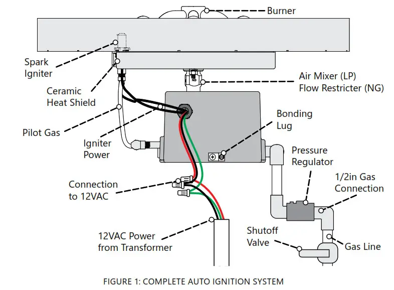
AUTOIGNITION INSTALLATION
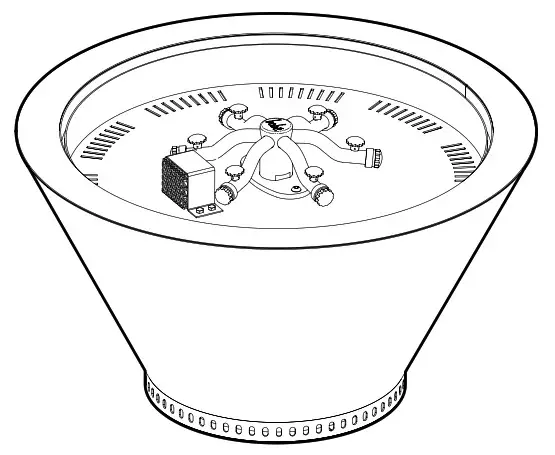
AUTOIGNITION COMPONENTS
- All gas and electrical connections are on the box.
- Transformer: 120VAC to 12 VAC transformer is included.
- Pilot Connections: Probes connect to the side of the box to the SS burner and spark electrode. There is a dedicated gas line pre-installed for the pilot flame.
- Other Items
- Air mixer: Pre-installed with Liquid Propane units
- Flow restrictor: Pre-installed with Natural Gas units
- Gas flow regulator: Pre-installed with 18in the flexible gas line
- Shut-off valve: Not included
IMPORTANT INFORMATION FOR PROPANE UNITS
- Air mixers required for Liquid Propane. For propane units, the correct air mixer should come pre-installed.
- Do not attempt to move, adjust or remove the air mixer for LP units. Failure to do so could result in personal injury and damage to the unit/property.
- Vent collars for an air mixer intake on a propane system should not be obstructed.
- Our units are NOT intended to be used with small portable LP tanks.
GAS CONNECTION
a. Before beginning, ensure the gas line is turned OFF.
b. Run 1/2” gas line to the inlet connection of the pre-installed regulator.
- Each unit ships with a regulator pre-installed. All installations must have gas regulator installed to maintain the gas pressure to the system.
- The regulator should be installed horizontally. The directional arrow should point away from the gas source and towards the gas valve.
- The gas regulator should be placed near the bottom of the fire feature such that it is not affected by the temperature from the burner.
c. Use pipe dope/joint compound on ALL threaded fittings EXCEPT flared fittings.
d. Verify all gas connections are tightened securely. ALWAYS perform leak tests and make repairs as needed.
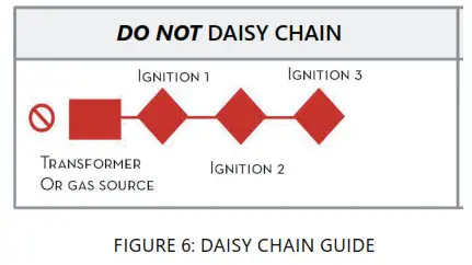
e. DO NOT daisy chain the gas lines. (See Section D)
f. A shut-off valve must be installed at each fire feature or valve. The primary gas valve must be located where it can be easily accessible so that the gas can be shut off quickly in case of an emergency.
g. Keep pipe length and elbows to a minimum to eliminate unnecessary pressure drops.
h. The use of a corrugated gas line can cause unwanted noise.
ELECTRICAL CONNECTION
a. Power Requirements
- Autoignition requires a minimum of 12 VAC
- The included transformer steps down from 120 VAC to 12VAC.
- The installer should check the voltage after installation to ensure proper values.
- Max length of wire from the transformer to the system is up to 75ft with 16 Gauge wire.
- For distances over 75ft – 150ft use 14 Gauge wire.
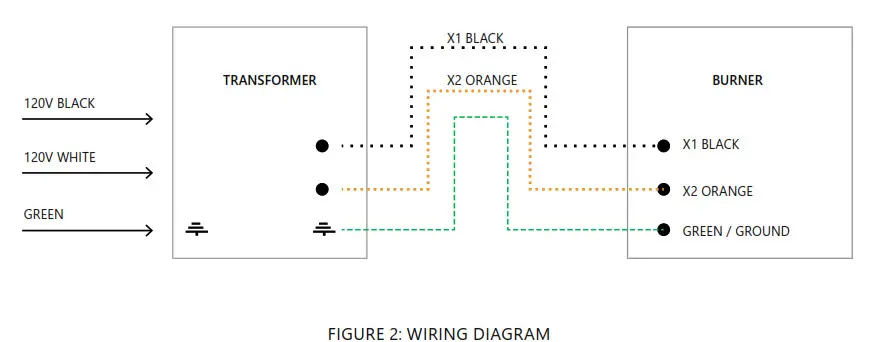
b. Connections (Fig 2)
- Run the electrical cable through an approved conduit. Conduit should be sealed to prevent gas settling or intrusion.
- Connect 120V to the included or approved Pool & Spa Rated Class 2 transformer (T).
- There are three wire connections on the side of the auto igniter. Connect 12V power from the transformer using wire nuts (3).
- Wrap wire nuts with electrical tape or use waterproof wire nuts to prevent moisture from getting in. Make sure wire nuts are positioned away from the bottom of the burner assembly.
- Connect ground from incoming power. (If required by local codes)
- Do not “daisy chain” electrical lines. (See Section D). Each transformer can supply up to four auto ignitor connections.
- The igniter contains a bonding lug on the bottom. To install, loosen the set screw, insert the bond wire into the hole and tighten the setscrew until the bond wire is secured into place.
CHECK SYSTEM
a. Perform all above-listed safety checks before startup. Before operating smell all around the appliance area for gas odors and next to the floor because some gases are heavier than air and will settle on the floor.
b. Ensure any person standing close to the fire feature is aware you will be turning the fire feature on prior to actually turning it on.
c. Do not add glass or rock media to the pan until a system test is complete.
d. At each burner assembly, check that the spark electrode is arcing from the pilot to the button. You should be able to hear and see the electrode spark. If there is no spark, make sure that the burner assembly is receiving 12VAC from the control panel.
e. Allow the unit to run for approximately five minutes then turn off.
f. After all units have been lit, they can be adjusted for flame size.
g. Turn on the system and check for re-ignition.
OPERATION & MAINTENANCE
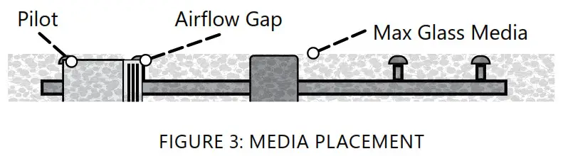
GLASS OR ROCKFILL MEDIA
- Use only approved fire glass or rock media on burners. Incorrect media can melt or explode leading to bodily injury or product damage.
- Glass media max level: fill up to 1/4in above the burner height.
- For glass or rockfill media, leave an airflow gap around the ventilation slots for the pilot lightbox.
BURNER SETUP
- Prior to turning the appliance on visually inspect fire feature to ensure debris such as leaves or other combustible material has not been collected inside the feature. This could burn and emit embers once the fire feature is turned on.
- Each burner should have a flame height of approximately 12” – 15” from the top of the pan.
- Each burner should be adjusted as required so that the flame size at each burner is similar in appearance to each other.
- Install decorative rock or glass on top of the “burner support” and burner assembly. Do not completely cover/ obstruct the burner.
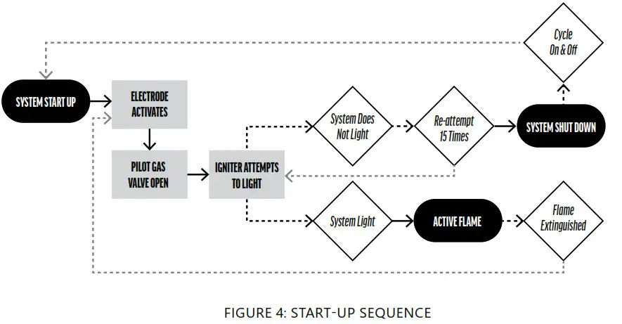
STARTUP
a. WARNING: Perform all above-listed safety checks before startup.
b. Before operating, smell around the appliance area for gas odors and next to the floor because some gases are heavier than air and will settle on the floor.
c. Ensure any person standing close to the fire feature is aware you will be turning the fire feature on prior to actually turning it on.
d. Turn System on.
e. If the system locks, reset by turning power OFF and then back ON.
f. The pilot flame will ignite. The main gas valve will open after the pilot flame is lit. If the main fire does not ignite, the system will cycle and attempt to light again.
g. If the pilot flame is extinguished at any time, the system will shut down. It will automatically attempt to restart again with the ignition sequence.
h. Once installed, the gas control valve should not be used to adjust the flame.
MAINTENANCE & CARE
- If any repairs are required, contact a licensed professional.
- Burner
- Inspect the burner before each use of the appliance. If there is any evidence that the burner is damaged, it must be replaced before operating.
- Periodically clean the burner assembly with a wet cloth or cleaning solution to remove carbon build-up. The frequency of the cleaning will depend on usage. Clean burners as necessary using compressed air.
- Periodically inspect the underside of the burner assembly for any signs of excessive temperatures.
- Check that all gas connections are tight.
- The burner assembly should be covered and protected from snow and ice. The burner should not be operated in high wind conditions.
- Visually inspect burner holes for debris/insect infestation.
- Pilot assembly requires at least yearly maintenance. Clean the carbon build up on the spark electrode and pilot using compressed air
- Inspect the gas line regularly. If the line shows evidence of excessive abrasion or wears or if the line is damaged, it must be replaced before use.
- USE THE SYSTEM! If the feature has been inactive for an extended period, turn the fire feature on to ensure proper operation.
MATERIAL CARE
COPPER
PATINA: Dark brown to green to blue. All copper products will patina. Patina is a natural process of oxidation where copper reacts to the elements and produces a series of colors that build up in order to protect the copper. The final color can vary widely depending on location, environment, and other factors.
WHAT COLOR WILL MY PRODUCT BE?
All products ship in their natural copper state. Depending on where they are stored or transported, patina may begin to develop. It is very likely the color may change between manufacture and delivery and will continue to patina after installation.
Copper can be cleaned after installation to reset the patina process.
CLEANING
- Patina color may vary from piece to piece, even when delivered on the same day. If you prefer to restore the material after
installation, a cleaning solution such as TarnX® may be used. - Hand Prints/Water Spots: Products develop handprints from handling or water stains from water testing. The natural patina process will cover up the markings as the whole piece begins to darken.
STAINLESS STEEL
PATINA
Stainless steel does not develop a patina.
CLEANING
- Stainless steel is steel that is “stain-less” however, this DOES NOT MEAN THAT STAINLESS STEEL WILL NEVER RUST OR CORRODE. Stainless steel can show water spots and deposits of minerals or other natural substances that appear orange, white, and/or brown. We suggest regular cleaning, at least once a month.
- Use distilled, soft or purified water (preferably warm) while cleaning and as a last rinse. Dry with a soft cloth.
- General maintenance can be done with a soft cloth. Windex works well if you want to remove water spots. Otherwise, a mild
soap or vinegar (1 part vinegar to 3 parts water) will remove light buildup. - Try to go in the direction of the natural polishing grains
- Heavier build-up can be cleaned using very fine red Scotch-Brite™ cleaning pads.
- In many cases, cleaning over time will greatly reduce the reappearance of build-up.
SALTWATER
Stainless steel is not warranted for use in or around saltwater. Our products are made of 316 marine-grade Stainless Steel.
Stainless steel can get water spots and stainless steel can get deposits of minerals or other natural substances that appeared, white and/or brown. If this happens you’ll need to clean the areas each time the build-up occurs and after 3-6 cleanings the problem areas should be free of any build-up returning.
TROUBLESHOOTING
| SITUATION | POSSIBLE CAUSE | CORRECTIVE ACTION |
| Pilot will not light | Air in gas line | On a new install, it may take multiple attempts to completely purge air. On an existing install, check for leaks. |
| Debris in gas line | Confirm gas line is clear (insulation, dirt, plastic, excessive pipe sealer, etc..) | |
| Igniter element is damaged | Replace igniter element | |
| High winds | Wait for the wind to subside or rotate the pan so wind does not blow across pilot. | |
| Pilot will not spark | Check voltage to the burner. If no voltage, replace the transformer. If correct voltage is detected, replace the ignition module. | |
| No pilot gas | Turn gas off and confirm pilot solenoid is energizing. If not energizing replace the ignition module. If energizing but not opening, replace the gas manifold. | |
| Incorrect gas pressure | Confirm proper gas pressures. Check for leaks. A regulator must be installed at each burner. | |
| Incorrect gas pressure | Confirm proper gas pressures. Check for leaks. | |
| The system will not light / will not stay lit but the pilot flame is lit | Improperly applied media | Remove excess media on the burner and remove the excess media near the pilot housing |
| Pilot is lit but the main burner will not light | Solenoid failure | Check for signs of overheating. If the valve is buzzing or will not energize, replace the ignition module. |
| System with lava rock has a small flame | Wet/damp lava rock | Lava rock is porous and will hold moisture. As the heat dries the lava rock out the flame should grow larger. |
| Burner or pilot will not shut off | Valve is stuck or dirty | Replace the gas manifold |
| System shutdown due to high temperature | Temperature exceeding the limit | Adequate ventilation should be provided per instructions |
| Whistling sound | The corrugated gas line used for installation | Use whistle-free hose – Adjust hose to create the path of least resistance for gas. |
| A system with propane does not burn correctly / is very black / produces a lot of soot. | Lack of ventilation will cause improper burning or failure | Confirm air mixer is installed correctly. Check for proper ventilation do not block ventilation paths in the system. |
| Propane source may be introducing impurities into the system | Check with your propane provider |
COMMON ISSUES/MISTAKES
- Check line connections – do not daisy chain gas or electrical connections. (see Section C)
- Check gas pressure for natural gas and propane. (see Section B)
- If using with propane gas – ONLY use with air mixer correctly installed. (See Fig 2) The ½ “ air mixer for propane includes stamped marking for gas flow direction. Air mixer is not required with natural gas.
- Check electrical voltage and connections.
- Check ground connections. (if required)
- Upon completing the gas line connection, a small amount of air will be in the lines. When first lighting the burner, it will take a few minutes for the lines to purge themselves of this air. Subsequent lighting of the appliance should not require such purging.
TROUBLESHOOTING
HOW TO PERFORM A LEAK TEST
a. Prepare a leak testing solution of soapy water by mixing in a spray bottle one part liquid soap with one part water.
b. Make sure all the control knobs are in the OFF position.
c. Turn on the gas.
d. Apply the leak-testing solution by spraying it on joints of the gas delivery system. Blowing bubbles in the soap solution indicates that a leak is present.
e. Stop a leak by tightening the loose joint or by replacing the faulty part with a replacement part recommended by the manufacturer.
f. Turn the control knob back to the full OFF position.
g. If you are unable to stop a leak: Please consult a gas specialist. Shut off the gas supply to the feature and release pressure in the hose and manifold. Call/consult an authorized gas appliance service technician or a liquid propane gas dealer. DO NOT use the appliance until the leak is corrected.
Perform a leak test at least once a year whether the gas supply has been disconnected or not. Whenever any part of the gas system is disconnected or replaced, perform a leak test. As a safety precaution, remember to always leak test outdoors in a well-ventilated area. Never smoke or permit sources of ignition in the area while doing a leak test. Do not use a flame, such as a lighted match to test for leaks.
SAVE THESE INSTRUCTIONS
INSTALLER – LEAVE THIS INSTRUCTIONS WITH HOMEOWNER
Record Information on this System Below & Keep for Your Records
Installer ___________________________________________
System Purchased From _______________________________
Installation Date _____________________________________
Serial Number _______________________________________
![]()
CMP, LLC
36 HERRING ROAD, NEWNAN, GA 30265
WWW.C-M-P.COM/Bobe
0621sb REV E


