AIMCO LIT-MAN350 UFT Series Joint Simulator
Operations Instructions
These testers are capable of simulating four different joints: A, B, C, and D (hard, medium-hard, medium-soft, and soft, respectively).
A Joint: C and D valves closed (clockwise) and the A joint sleeve installed between the Plunger Bushing and the Spindle Nut.
B Joint: C and D valves closed (clockwise) and remove the A joint sleeve.
C Joint: Open the C valve under the side cylinder one turn (counter-clockwise). The D valve remains closed.
D Joint: Open both the C and D valves (one turn).
Changing Bolt Kits
To change the bolt:
- Remove the test bolt.
- Remove the Spacer and Plunger Bushing.
- Remove the Allen Head Bolt that holds the Spindle Nut. This is located on the side of the tester by the D valve lever.
- Remove the Spindle Nut.
- Install the new Spindle Nut.
- Install the Allen Head Bolt back through the Spindle Nut.
- Install the Plunger Bushing, Spacer, and new bolt.
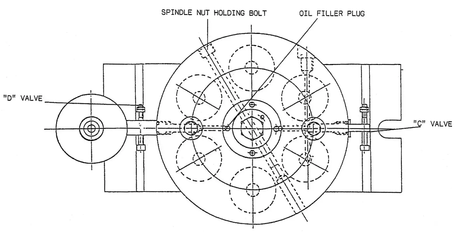
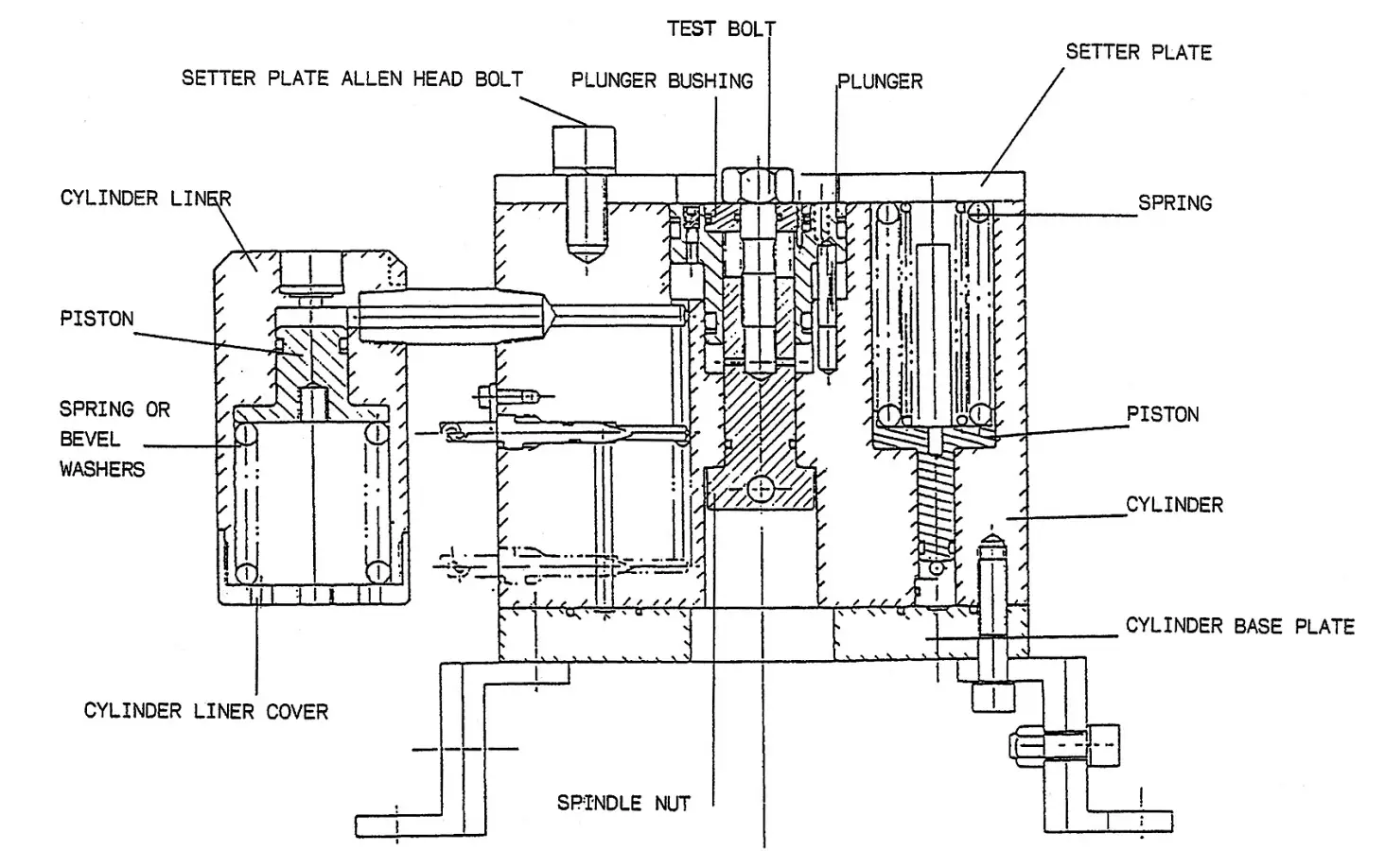
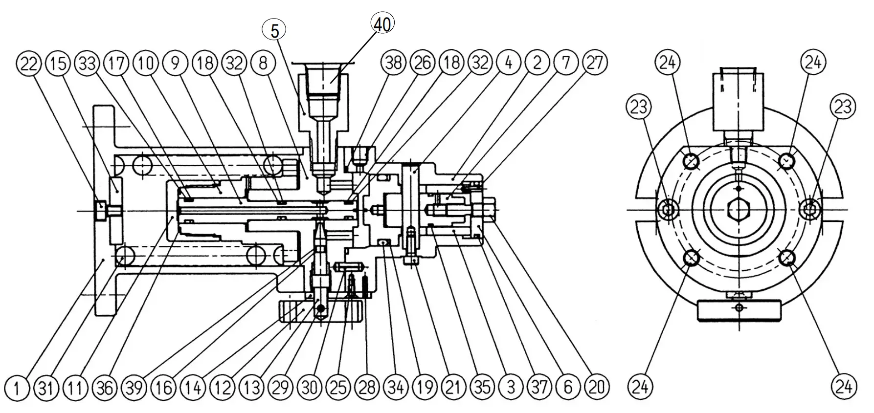
Breakdown of the UFT-S Joint Simulator
Top View of UFT-S Joint Simulator
Side View of UFT-S Joint Simulator
Breakdown of the UFT-S10 Joint Simulator
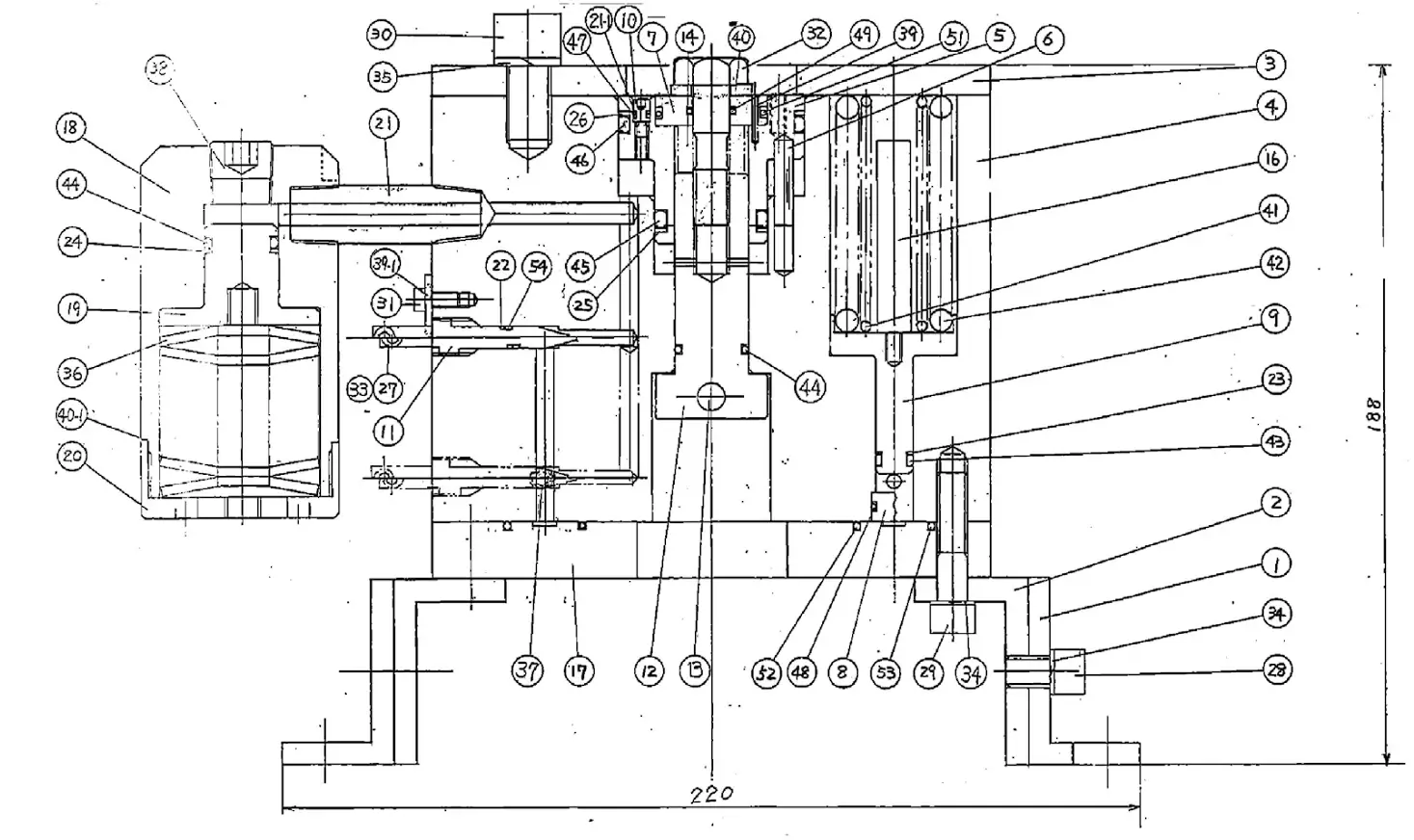
Index No. | Code No. | Description | Qty. |
1 M8 Type M6 Type | 839-965-5 878-903-1 878-908-1 | Base Setting Plate Rear Plate Cylinder Plunger Pilot Pin Plunger Bushing Cylinder Bushing Piston Oil Plug Valve Spindle Nut (M10) Stopper Bushing (M10) Piston Spring Guide Front Plate Oil Casing Piston Oil Casing Cover Connecting Screw Supporter Ring (3.0 x 5.0 x 1) Back-up Ring (4.2 x 6 x 1) Back-up Ring (P7) Back-up Ring (P16) Back-up Ring (P24) Back-up Ring (P44) Allen Head Bolt (M3 x 50) Allen Head Bolt (M8 x 15) Allen Head Bolt (M8 x 30) Allen Head Bolt (M12 x 20) Hexagon Round Head Bolt (M4 x 8) Hexagonal Bolt (M10 x 35) (UFT) Hexagon Nut (1-M3) Spring Washer (2-8S) Spring Washer (2-12S) Belleville Spring (42 x 14.3 x 2.5) Allen Head Plug (1/8) Allen Head Plug (3/8) Roll Pin (2.5 x 12) Spacer (13 x 4.2 x1.5) Spacer (22 x 10.5 x 3) (H) Adjusting Spacer (53 x 48.2 xT) Spring (21 x 65) Spring (33 x 65) O-Ring (P6) O-Ring (P15) O-Ring (P24) O-Ring (P44) O-Ring (SNS-2) (NOK) O-Ring (P9) O-Ring (SNS-10) O-Ring (SNS-22) O-Ring (SNS-70) O-Ring (SNS-112) O-Ring (SNS-4) (NOK) Bushing (M8)
Bushing (M6) | 2 1
1 |
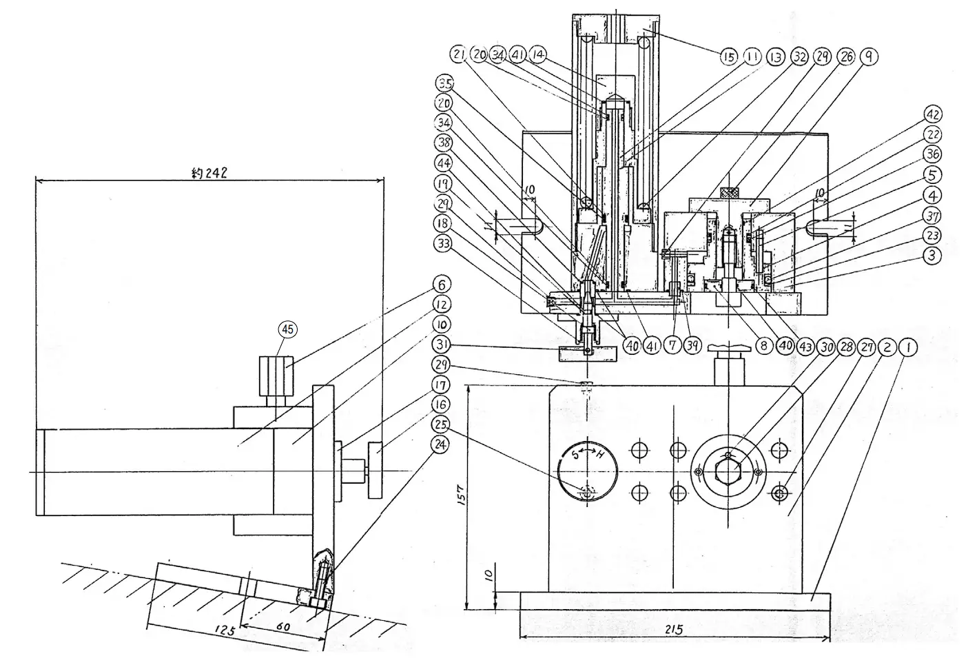
Breakdown of the UFT-S16 Joint Simulator
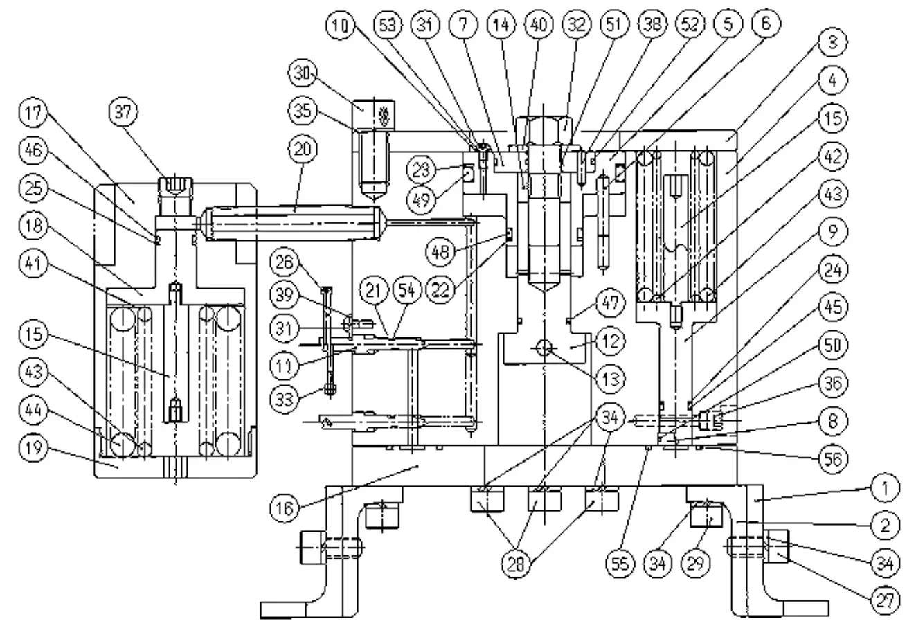
| Index No. | Code No. | Description | Qty. |
1 M14 Type M12 Type | 839-965-6
878-777-1
878-781-1 | Setting Stand Setting Plate Rear Plate Cylinder Plunger Pilot Pin Plunger Bushing (M16) Cylinder Bushing Piston Spacer Valve Spindle Nut Stopper Bushing (M16) Piston Spring Guide Front Plate Oil Casing Piston (large) Oil Casing Cover Connecting Screw Back-up Ring (4.2 x 6 x 1) Back-up Ring (P32) Back-up Ring (P70) Back-up Ring (P12) Back-up Ring (P16) Allen Head Bolt (M3 x 50) Allen Head Bolt (M10 x 20) Allen Head Bolt (M10 x 35) Allen Head Bolt (M10 x 45) Allen Head Bolt (M14 x 30) Hexagon Round Head Bolt (M4 x 6) Hexagonal Bolt (M16 x 50) (UFT) Hexagon Nut (1-M3) Spring Washer (2-10S) Spring Washer (2-14S) Allen Head Plug (1/8) Allen Head Plug (3/8) Roll Pin (4 x 16) Spacer (13 x 4.2 x 1.5) Spacer (35 x 16.5 x 3) (H) Adjusting Spacer (68 x 30 x T) Spring (23 x 75) (4.0) Spring (37.5 x 75) (7.0) Spring (64 x 75) (12.0) O-Ring (P11) O-Ring (P15) O-Ring (P22) O-Ring (P32) O-Ring (P70) O-Ring (JW1530-15) O-Ring (SNS-16) O-Ring (SNS-46) O-Ring (SNS-3) (NOK) O-Ring (SNS-4) (NOK) O-Ring (SNS-100)
O-Ring (SNS-150)Plunger Bushing (M14) Plunger Bushing (M12) | 2
1
1 |
Operations Instructions
UFT-6, UFT-10, UFT-16 and UFT-24
Warning
- Always operate test bolt within specified torque range.
- Always secure joint simulator before use.
Operation Cautions
- Never change joints without loosening the test bolt.
- Check the test bolt every 50,000 cycles.
- Double-check all bolts after changing joints and bolt sizes.
- Never use sloppy sockets or extensions.
- Always use Power Driver Sockets per ANSI B107.2.
Operation Instructions
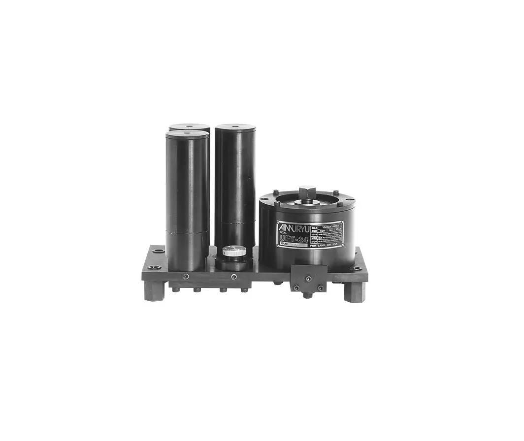
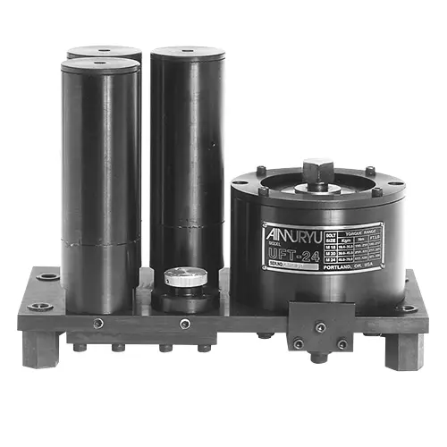
UFT-6, UFT-10, UFT-16 and UFT-24
There are two joints on these models: A “B” joint (medium-hard) and a “C” joint (medium-soft). To change these
joints, simply turn the silver knob on the front of the tester clockwise until it stops for the “B” joint and counterclockwise until it stops for the “C” joint.
Changing Bolt Kits
UFT-10, UFT-16 and UFT-24
- Each bolt kit has certain springs that go with them. Please consult the chart below to match the right spring with the size of bolt that you are using.
- To change bolts:
a) Remove the test bolt and Plunger Bushing.
b) On the UFT-10 and UFT-16, remove the two Allen Head Bolts from the Spindle Nut located on the back of the testers. Insert the new Spindle Nut and re-install the Allen Head Bolts.
c) Install the new bolt and Plunger Bushing.
d) Remove the Cylinder Liner Casing Cover and change out the springs. Reinstall the Cylinder Liner Casing Cover.
| Model | Bolt Size | Spring Size Installed Into the Chamber and the Quantity Used | ||
| UFT-10 | M6 | 48.5 x 120 | (8.5) | 1 pc. |
| M8 | 51 x 120 | (9.5) | 1 pc. | |
| M10 | 51 x 120 | (10.0) | 1 pc. | |
| UFT-16 | M12 | 49 x 120 | (9.0) | 2 pcs. |
| M14 | 49 x 120 | (9.0) | 2 pcs. | |
| M16 | 49 x 120 | (9.5) | 2 pcs. | |
| UFT-24 | M18 | 59 x 115 | (11.0) | 3 pcs. |
| M20 M20 | 59 x 115 35.5 x 10⁵ | (11.0) (6.6) | 3 pcs. 3 pcs. | |
| M24 M24 | 59 x 115 35 x 105 | (11.0) (7.0) | 3 pcs. 3 pcs. | |
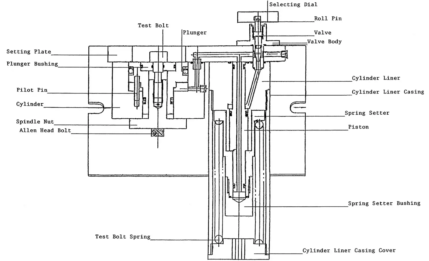
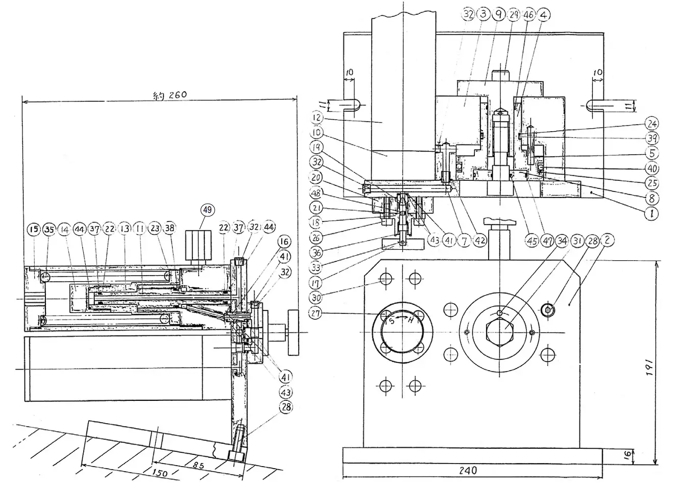
Breakdown of the UFT-BC Joint Simulator
Front View
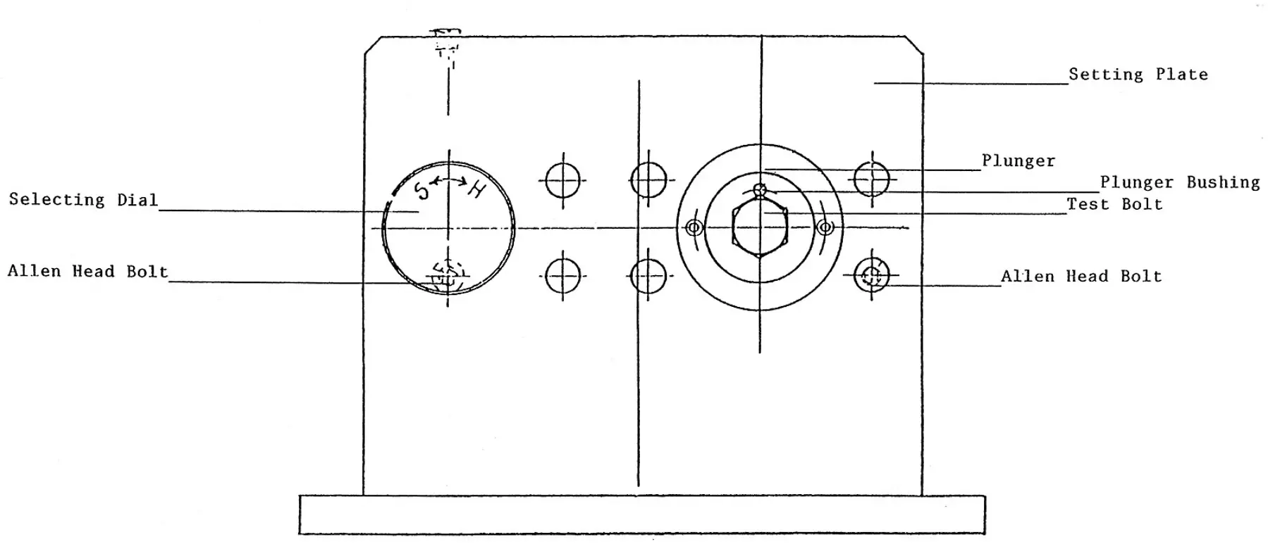
Top View
Breakdown of the UFT-6 Joint Simulator
| Index No. | Code No. | Description | Qty. |
2
M4 Type | 840-965-4 840-286-4 840-600-4 840-318-4 840-049-5 840-604-4 840-359-4 840-676-4 840-546-4 840-164-4 840-175-4 840-107-5 840-100-5 840-133-4 840-166-4 944-005-0 944-011-0 944-027-0 944-028-0 946-969-0 975-550-0 945-010-0 945-108-0 945-245-0 945-325-0 948-423-0 966-110-0 973-008-0 973-010-0 973-130-0 973-210-0 976-768-0 990-004-0 990-007-0 990-027-0 990-912-0 990-916-0 990-917-0 990-928-0 990-972-0 966-102-0 878-850-1 975-550-1 878-763-1 878-764-1 946-968-0 975-549-0 990-912-0 990-917-0
878-766-1 | Setting Stand Cylinder Plunger Pilot Pin Setting Screw for Pressure Sensor Plunger Bushing (M6) Spindle Nut (M6) Cylinder Liner Piston Retainer Retainer Bushing Valve Lever Valve Valve Wheel Nut Flange Spring Holder Spacer Support Ring (42 x 6 x 1) Back-up Ring (P9) Back-up Ring (P6) Back-up Ring (P28) Hexagon Bolt (M6 x 18) (UFT) Spacer (14 x 6.5 x 2) (H) Allen Head Bolt (M4 x 10) Allen Head Bolt (M5 x 8) Allen Head Bolt (M6 x 45) Allen Head Bolt (M8 x 25) Allen Flush Head Screw (M3 x 6) Allen Head Plug (NPT1/16) Roll Pin (2 x 8) Roll Pin (2 x 10) Roll Pin (3 x 30) Roll Pin (4 x 10) Spring (52 x 80) (9.0) O-Ring (P6) O-Ring (P9) O-Ring (P28) O-Ring (SNS-14) O-Ring (SNS-18) O-Ring (SNS-24) O-Ring (SNS-38) O-Ring (SNS-4) Allen Head Plug (3/8) Test Socket (10 x 3/8) Spacer (14 x 6.5 x 2) (H) Plunger Bushing (M5) Spindle Nut (M5) Hexagon Bolt (M5 x 17) (UFT) Spacer (12 x 5.5 x 2) (H) O-Ring (SNS-14) O-Ring (SNS-24)
Plunger Bushing (M4) | 1 1 1 1 1 1 1 1 1 1 1 1 1 1 1 1 1 2 1 1 1 1 1 1 2 4 1 1 1 1 1 1 2 1 1 1 1 1 1 1 1 1 1 1 1 |
Breakdown of the UFT-10 Joint Simulator
| Index No. | Code No. | Description | Qty. |
1 M8 Type M6 Type | 840-965-5 840-718-5 840-286-5 840-600-5 840-318-5 840-049-5 840-674-5 840-604-5 840-359-5 840-676-5 840-546-5 840-905-5 840-164-5 840-175-5 840-906-5 840-107-5 840-014-5 840-100-5 944-005-0 944-011-0 944-017-0 944-025-0 944-045-0 945-214-0 945-230-0 945-320-0 945-967-0 946-972-0 975-552-0 966-110-0 973-114-0 973-126-0 976-767-0 979-312-0 990-007-0 990-014-0 990-024-0 990-045-0 990-904-0 990-905-0 990-908-0 990-913-0 990-916-0 990-924-0 990-972-0 966-102-0 878-770-1
878-773-1 | Setting Stand Setting Plate Cylinder Plunger Pilot Pin Pressure Gauge Stand Screw Cylinder Bushing Plunger Bushing (M10) Spindle Nut (M10) Cylinder Liner Piston Cylinder Liner Casing Spring Setter Spring Setter Bushing Cylinder Liner Casing Cover Selecting Dial Valve Body Valve Backup Ring (4.2 x 6 x 1) Backup Ring (P9) Backup Ring (P14) Backup Ring (P24) Backup Ring (P48A) Allen Head Bolt (M6 x 14) Allen Head Bolt (M6 x 30) Allen Head Bolt (M8 x 20) Hexagon Round Head Bolt (M6 x 25) Hexagonal Bolt (M10 x 35) (UFT) Spacer (22 x 10.5 x 3) (H) Allen Head Plug (NPT1/6) Roll Pin (3 x 14) Roll Pin (3 x 26) Spring (51 x 120) (10.0) Inner Snap Ring (IRTW-12) O-Ring (P9) O-Ring (P14) O-Ring (P24) O-Ring (P48A) O-Ring (SNS-6) O-Ring (SNS-7) O-Ring (SNS-10) O-Ring (SNS-15) O-Ring (SNS-18) O-Ring (SNS-30) O-Ring (SNS-4) (NOK) Allen Head Plug (3/8) Plunger Bushing (M8)
Plunger Bushing (M6) | 1 1 1 1 4 1 1 1 1 1 1 1 1 1 1 1 1 1 1 1 2 1 1 1 3 2 2 6 1 3 1 1 1 1 1 1 2 1 1 1 1 1 3 2 1 1 1 1 1 1
1 |
Breakdown of the UFT-16 Joint Simulator
| Index No. | Code No. | Description | Qty. |
1 M14 Type M12 Type | 840-965-6 840-718-6 840-286-6 840-600-6 840-318-6 840-049-5 840-674-6 840-604-6 840-359-6 840-676-5 840-546-5 840-905-5 840-164-5 840-175-5 840-906-5 840-567-6 840-107-5 840-014-5 840-100-5 840-027-6 944-005-0 944-011-0 944-017-0 944-032-0 944-070-0 945-214-0 945-235-0 945-320-0 945-425-0 945-967-0 946-975-0 975-557-0 966-110-0 973-130-0 973-216-0 976-764-0 979-312-0 990-007-0 990-014-0 990-032-0 990-055-0 990-904-0 990-907-0 990-908-0 990-913-0 990-914-0 990-923-0 990-937-0 990-972-0 966-102-0
878-777-1
878-781-1 | Setting Stand Setting Plate Cylinder Plunger Pilot Pin Pressure Gauge Stand Screw Cylinder Bushing Plunger Bushing (M16) Spindle Nut (M16) Cylinder Liner Piston Cylinder Liner Casing Spring Setter Spring Setter Bushing Cylinder Liner Casing Cover Bushing Selecting Dial Valve Body Valve Separator Back-up Ring (4.2 x 6 x 1) Back-up Ring (P9) Back-up Ring (P14) Back-up Ring (P32) Back-up Ring (P70) Allen Head Bolt (M6 x 14) Allen Head Bolt (M6 x 35) Allen Head Bolt (M8 x 20) Allen Head Bolt (M10 x 25) Hexagon Round Head Bolt (M6 x 25) Hexagonal Bolt (M16 x 50) (UFT) Spacer (34 x 16.5 x 3) (H) Allen Head Plug (NPT1/6) Roll Pin (3 x 30) Roll Pin (4 x 16) Spring (49.5 x 120) (9.5) Inner Snap Ring (ITRW-12) O-Ring (P9) O-Ring (P14) O-Ring (P32) O-Ring (P70) O-Ring (SNS-6) O-Ring (SNS-9) O-Ring (SNS-10) O-Ring (SNS-15) O-Ring (SNS-16) O-Ring (SNS-26) O-Ring (SNS-46) O-Ring (SNS-4) (NOK) Allen Head Plug (3/8)
Plunger Bushing (M14)
Plunger Bushing (M12) | 1 1 1 1 4 1 1 1 1 2 2 2 2 2 2 2 1 1 1 1 1 4 2 1 1 2 4 7 2 4 1 1 4 1 1 2 1 4 2 1 1 7 1 4 4 1 1 1 1 1
1
1 |
Breakdown of the UFT-24 Joint Simulator
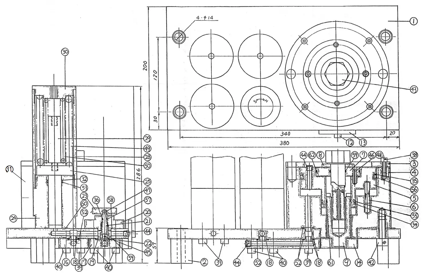
| Index No. | Code No. | Description | Qty. |
| 1 2 3 4 5 6 7 8 9 12 13 14 15 16 17 18 19 20 21 22 23 24 25 26 27 28 29 30 31 32 33 34 35 36 37 38 39 40 41 42 43 44 45 46 47 48 49 50 51 52 53 54 55 56 57 58 59 60 61 62 63 M20 Type M18 Type | 840-718-7 840-397-7 840-285-7 840-286-7 840-600-7 840-318-7 840-604-7 840-357-7 840-359-7 840-800-7 840-521-7 840-520-7 840-522-7 840-090-7 840-098-7 840-567-7 840-101-7 840-014-7 840-114-7 840-100-7 840-107-5 840-676-7 840-546-7 840-675-7 840-545-7 840-905-7 840-547-7 840-906-7 966-101-0 944-021-0 944-026-0 944-048-0 944-155-0 944-206-0 945-212-0 945-216-0 945-330-0 945-342-0 945-429-0 945-446-0 946-978-0 966-100-0 973-112-0 973-124-0 973-130-0 973-322-0 976-775-0 976-716-0 979-407-0 990-014-0 990-020-0 990-013-0 990-046-0 990-115-0 990-904-0 990-919-0 990-917-0 990-924-0 990-929-0 990-991-0 878-877-1
878-785-1
878-790-1 | Setting Stand Setting Plate Cylinder Rear Plate Cylinder Plunger Pilot Pin Plunger Bushing (M24) Spindle Spacer (53 x 24.5 x 5) (H) Spindle Nut (M24) Socket Pin Socket Plate Socket Socket Bushing Air Inlet Bushing Air Inlet Bushing (B) Bushing Valve Bushing Valve Body Valve Spindle Valve Selecting Dial Cylinder Liner Piston Cylinder Liner Piston Liner Casing Piston Rod Liner Casing Setter Allen Head Plug (1/4) Back-up Ring (P22) Back-up Ring (P25) Back-up Ring (P50) Back-up Ring (P115) Back-up Ring (6.1 x 8 x 1) Allen Head Bolt (M6 x 12) Allen Head Bolt (M6 x 169) Allen Head Bolt (M8 x 30) Allen Head Bolt (M8 x 45) Allen Head Bolt (M10 x 35) Allen Head Bolt (M12 x 30) Hexagon Head Bolt (M24 x 90) (UFT) Allen Head Plug (1/8) Roll Pin (3 x 12) Roll Pin (3 x 24) Roll Pin (3 x 30) Roll Pin (5 x 24) Spring (59 x 115) (11.0) Spring (35 x 105) (7.0) Outer Snap Ring (E4) O-Ring (P14) O-Ring (P22) O-Ring (P25) O-Ring (P50) O-Ring (P115) O-Ring (SNS-6) O-Ring (SNS-22) O-Ring (SNS-24) O-Ring (SNS-30) O-Ring (SNS-36) O-Ring (SNS-67) Test Socket (3/4SQ x 36) (M24)
Plunger Bushing (M20)
Plunger Bushing (M18) | 1 1 1 1 1 4 1 1 1 1 1 1 1 1 1 1 1 1 1 1 1 1 1 2 2 3 3 3 1 1 2 1 1 1 2 4 10 10 2 4 1 6 1 1 1 1 3 3 1 4 1 3 1 1 1 1 2 3 1 1 1
1
1
|
Maintenance
- Inspect the Bolt and Spindle Nut every 50,000 cycles.
- Should the Plunger not come back up to the top of the Cylinder, then the tester is low on fluid. To fill the testerwith fluid, the tester must be level.
• Remove the two oil filler plugs from the plunger.
• Pull the plunger back up to the top of the cylinder.
• While holding the plunger up, fill the tester up through the filler holes with Dextron II.
• Reinstall the oil filler plugs.
• If the Plunger does not come back up to the top of the Cylinder, open all valves so that the UFT is set for the softest joint. Then tighten the test bolt pushing the plunger down and fluid into the plungers for the springs under the top plate. Now close the valves to set for hard joint, loosen the test bolt, remove the oil fill plugs and pull the plunger to the top of the cylinder. Fill with fluid, install the oil fill plugs and then open all valves to set for the softest joint. This may need to be done several times to certify the test bolt in the UFT. - If the Plunger continues to stay down, the tester has a damaged seal and must be repaired. After the damaged parts are replaced, follow the same fill procedures as abov
Certification of the UFT Joint Simulator
The UFT tester should be certified every 5,000 cycles.
Certification Procedures
1. On the chart below, find the UFT model you are certifying.
2. Next, find the bolt size.
3. With a torque wrench, tighten to the recommended snug torque.
4. Turn the torque wrench the number of degrees recommended from snug for each joint. The torque reading should be the same as shown on the chart.
5. If the readings do not match, the Test Bolt might be worn. Replace the Test Bolt and re-certify the tester. If the tester still does not match the chart, check the fluid level and/or all O-Rings and Supporter Rings for wea
Torque Values for Certifying Tester
| Model | Bolt Size | Snug Point Torque | B Joint at 60° from Snug | C Joint at 180° from Snug | D Joint at 180° from Snug | ||||
| ft. lbs. | Nm | ft. lbs. | Nm | ft. lbs. | Nm | ft. lbs. | Nm | ||
| UFT-S10 | M6 | 2 | 2.71 | 5.2-7.7 | 7.1-10.4 | 5.9-9.2 | 8.0-12.4 | 3.0-4.5 | 4.1-6.1 |
| M8 | 5.5 | 7.46 | 11.2-16.8 | 15.2-22.8 | 11.2-16.8 | 15.2-22.8 | 6.6-9.8 | 8.9-13.3 | |
| M10 | 11 | 15 | 19.5-29.2 | 26.4-39.6 | 18.6-27.9 | 25.2-37.8 | 12.5-18.8 | 17.0-25.5 | |
| UFT-S16 | M12 | 20.25 | 27.4 | 34.5-51.8 | 46.8-70.2 | 41-61.5 | 55.6-83.4 | 23.6-35.4 | 32.0-48.0 |
| M14 | 32.5 | 44 | 54.9-82.4 | 74.4-111.6 | 51.9-76.4 | 70.3-103.5 | 35.4-53.3 | 48.0-72.0 | |
| M16 | 54.25 | 73.5 | 88.6-132.8 | 120-180 | 83-122.6 | 112.5-166.1 | 57.3-85.9 | 77.6-116.4 | |
| 60° from Snug | 180° from Snug | ||||||
| UFT-6 | M5 | 1.8 | 2.5 | 2.4-3.6 | 3.3-4.9 | 2.9-4.3 | 3.9-5.8 |
| M6 | 3.7 | 5.0 | 5-7.5 | 6.8-10.2 | 6.5-9.7 | 8.8-13.2 | |
| UFT-10 | M6 | 3.7 | 5.0 | 5-7.5 | 6.8-10.2 | 5.2-7.9 | 7.1-10.7 |
| M8 | 5.75 | 7.8 | 9.4-14.2 | 12.8-19.2 | 10.3-15.5 | 14-21 | |
| M10 | 11.5 | 15.2 | 18.9-28.3 | 25.6-38.4 | 19.2-28.8 | 26-39 | |
| UFT-16 | M12 | 20.25 | 27.4 | 37.8-56.8 | 51.2-76.8 | 37.8-56.8 | 51.2-76.8 |
| M14 | 32.5 | 44 | 61.4-92.1 | 83.2-124.8 | 61.4-92.1 | 83.2-124.8 | |
| M16 | 50.5 | 68.5 | 76.7-115.1 | 104-156 | 79.7-119.6 | 108-162 | |
| UFT-24 | M18 | 70 | 95 | 129.9-195.6 | 176-265 | 135.8-203.7 | 184-276 |
| M20 | 108.5 | 147 | 200.7-301.1 | 272-408 | 211.7-318.8 | 288-432 | |
| M24 | 162.75 | 220 | 301.1-451.6 | 408-612 | 307-460.5 | 416-624 | |
| UFT-33 | M30 | 200 | 460-690 | 624-936 | 422-708 | 640-960 | |
List of Hexagon Head Bolts
| MODEL | PART NUMBER | BOLT SIZE |
| UFT-6 | 946-967-0 | M4 |
| UFT-6 | 946-968-0 | M5 |
| UFT-6 | 946-969-0 | M6 x 18 |
| UFT-S10 | 946-970-0 | M6 x 30 |
| UFT-S10 | 946-971-0 | M8 x 32 |
| UFT-S10 | 946-972-0 | M10 x 35 |
| UFT-10 | 946-970-0 | M6 x 30 |
| UFT-10 | 946-971-0 | M8 x 32 |
| UFT-10 | 946-972-0 | M10 x 35 |
| UFT-S16 | 946-973-0 | M12 x 45 |
| UFT-S16 | 946-974-0 | M14 x 50 |
| UFT-S16 | 946-975-0 | M16 x 50 |
| UFT-16 | 946-973-0 | M12 x 45 |
| UFT-16 | 946-974-0 | M14 x 50 |
| UFT-16 | 946-975-0 | M16 x 80 |
| UFT-24 | 946-976-0 | M18 x 80 |
| UFT-24 | 946-977-0 | M20 x 85 |
| UFT-24 | 946-978-0 | M24 x 90 |
AIMCO CORPORATE HEADQUARTERS
10000 SE Pine Street
Portland, Oregon 97216
Phone: (503) 254–6600
Toll Free: 1-800-852-1368
AIMCO CORPORATION DE MEXICO SA DE CV
Ave. Cristobal Colon 14529
Chihuahua, Chihuahua. 31125
Mexico
Phone: (01-614) 380-1010
Fax: (01-614) 380-1019
PO Box 16460, Portland, OR 97292-0460 | 800-852-1368 | Fax 800-582-9015
www.aimco-global.com