![]()
INSTALLATION GUIDE:
AWE EXHAUST SUITE FOR THE 4TH GEN 6.2L CHEVY SILVERADO 1500 AND GMC SIERRA 1500
For up-to-date fitment information, please visit the product page on AWE-Tuning.com.
THIS GUIDE IS INTENDED FOR THE FOLLOWING PART NUMBERS:
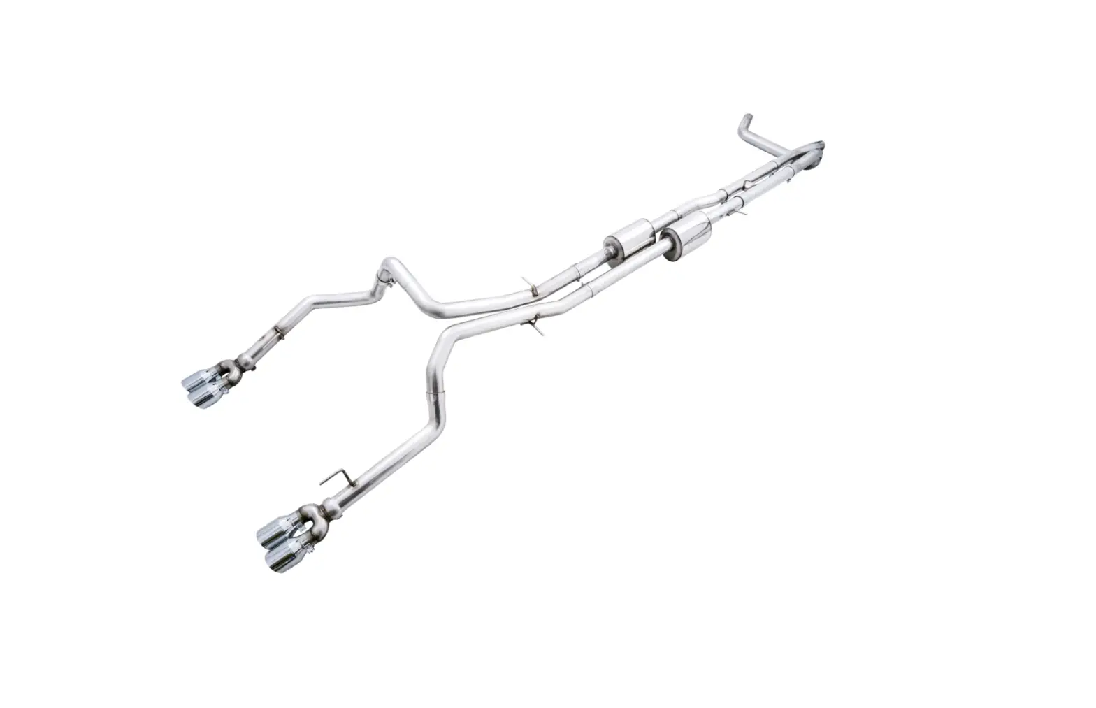
3015-42203 AWE 0FG Catback Split Rear Exit Exhaust for 4th Gen Silverado/Sierra 1500 6.2L- Quad Chrome Silver Tips
3015-43204 AWE 0FG Catback Split Rear Exit Exhaust for 4th Gen Silverado/Sierra 1500 6.2L – Quad Diamond Black Tips
Welcome to the AWE family, and congratulations on your purchase of the AWE Exhaust System for the 4th Gen Chevy Silverado 1500 6.2L and GMC Sierra 1500 6.2L.
Exquisite build quality and craftsmanship, coupled with industry leading performance, distinguish this exhaust system from all others.
*For up to the minute fitment information, be sure to visit the AWE website. As always, AWE Performance Specialists are standing by for any questions, right here.
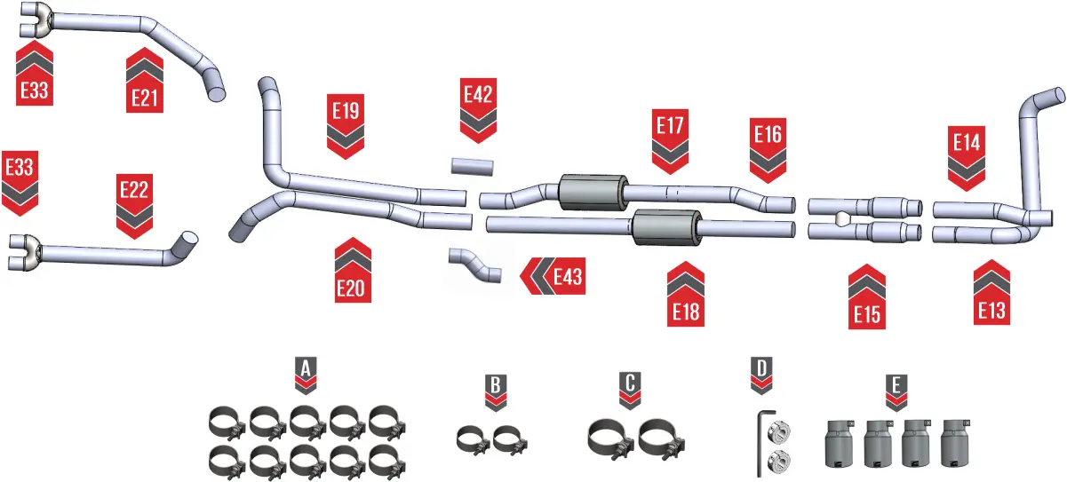
PARTS LIST (QUAD EXIT SYSTEM)
 Inspect ALL parts prior to disassembly of vehicle; If damaged or MISSING, please contact the place of purchase immediately. Ensure you have received both boxes of parts before beginning.
| Symbol | Part Number | Description | QTY |
E13 | Silverado 4th Gen 6.2L Driver Side Front Section | 1 | |
E14 | Silverado 4th Gen 6.2L Passenger Side Front Section | 1 | |
E15 | Silverado 4th Gen 6.2L H Pipe | 1 | |
E16 | Silverado 4th Gen 6.2L Mid Pipe Driver | 1 | |
E17 | Silverado 4th Gen 6.2L HR5 Section Driver | 1 | |
E18 | Silverado 4th Gen 6.2L HR5 Section Passenger | 1 | |
E19 | Silverado 4th Gen 6.2L Axle Tube Driver | 1 | |
E20 | Silverado 4th Gen 6.2L Axle Tube Passenger | 1 | |
E21 | Silverado 4th Gen 6.2L Tailpipe Driver | 1 | |
E22 | Silverado 4th Gen 6.2L Tailpipe Passenger | 1 | |
E33 | Silverado 4th Gen 5.3L/6.2L Tip Outlet (Quad 102 Outlet) | 2 | |
E42 | Silverado 4th Gen 6.2L Long Wheel Base Adapter Driver (straight) | 1 | |
E43 | Silverado 4th Gen 6.2L Long Wheel Base Adapter Passenger (bends) | 1 | |
180300 | AWE Band Clamp: 3″ | 10 | |
180250 | AWE Band Clamp: 2.5″ | 2 | |
SEC75 | 3″ Barrel Clamp (Bubble) | 2 | |
3910-11012 | Clamp-Kit | 1 | |
180010 | 4.00″ OD x 2.50″ ID, Slash Cut, Chrome Silver, AWE Tuning Logo, Intergrated Clamp | 4 | |
180011 | 4.00″ OD x 2.50″ ID, Slash Cut, Diamond Black, AWE Tuning Logo, Intergrated Clamp | 4 |
 NOTE: Always refer to the manufacturer’s service manual for precise torque specifications on all OEM fasteners.
 CAUTION: The exhaust may be VERY HOT — allow adequate time for the system to cool down before disassembly. Severe burns and injury will occur if skin comes into contact with a hot exhaust system.
NOTE: This is a large system to remove and install. We highly recommend you grab a friend to help out with the entire process.
NOTE: Soak all bolts and rubber hangers in penetrating oil before starting any work.
STEP 1
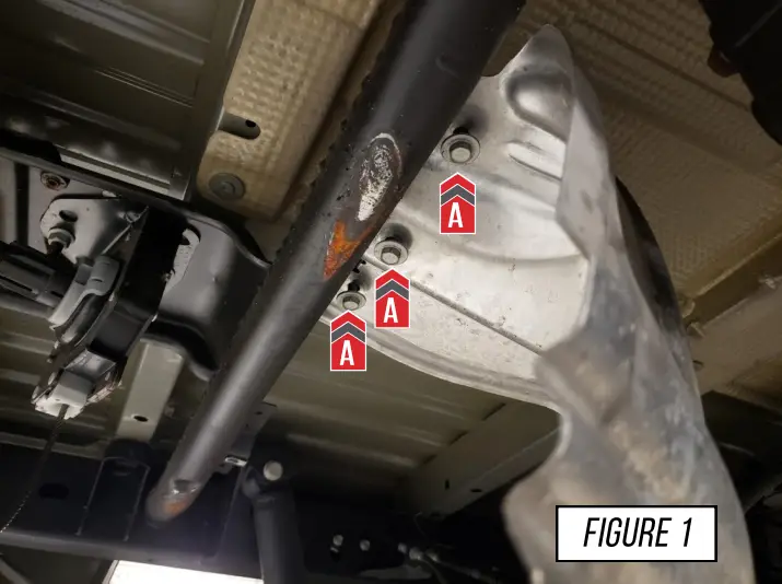
Begin removing your OE exhaust system by first removing your spare tire.
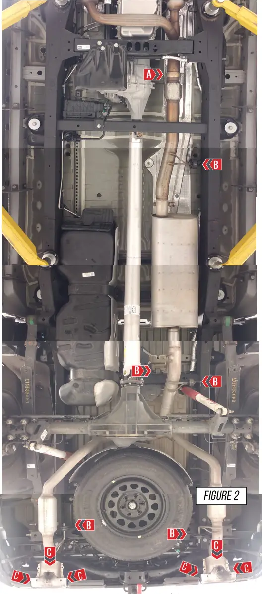
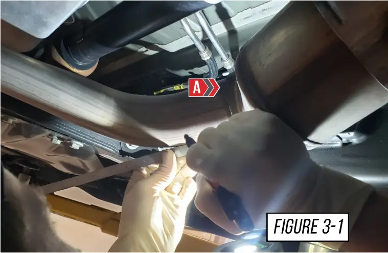
Next remove the OE heat shield, and hardware shown in Figure 1 at (A).
Note: This will be reinstalled after you remove the OE exhaust
STEP 2
Continue by removing the OE dual exit exhaust by following the steps, shown in Figure 2.
Soak all bolts and rubber hangers in penetrating oil before starting any work.
- To begin you will loosen the OE ball socket clamp located at (A), enough to separate the two components.
- Remove the 5 OE hangers from the exhaust shown at (B).
- With the OE exhaust no longer attached to the vehicle, remove the complete exhaust.
- Remove the OE tip bezels by removing the 3 bolts per side marked at (D). On each bezel, all 3 bolts are located on the top side.
Note: The OE tip bezels will not be reused.
Note: After the OE exhaust is completely removed, re-install the OE heat shield, and the spare tire.
STEP 3
Up next you will need to measure the cut points behind the catalytic converters on the front pipes.
The drivers side cut will be 25/16” from the weld (A) shown in Figure 3-1. Mark your cut point with a marker.
The passenger side cut will be 23/4” from the weld (B) shown in Figure 3-2. Mark your cut point with a marker.

IT IS EXTREMELY IMPORTANT THAT THESE MEASUREMENTS ARE ACCURATE, AS IT WILL AFFECT FITMENT
STEP 4
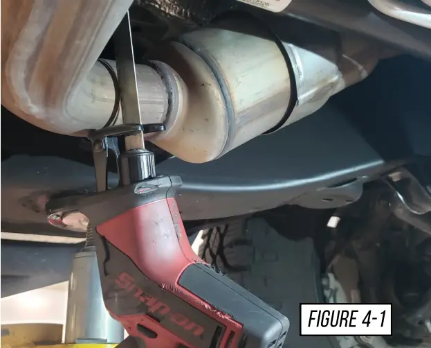
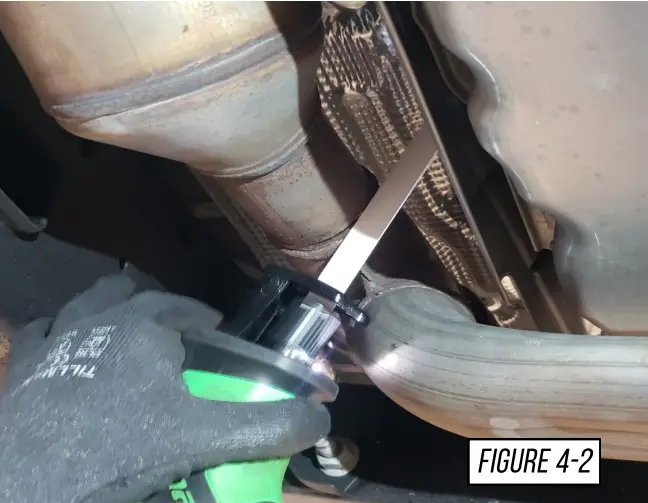
Once you have ensured that your cut measurements are correct. Cut each side on your mark, and remove the cut section from the truck.
Note: It is crucial that these cuts are accurate. Inaccurate cuts will affect fitment.
Make sure that the cuts are as straight as possible.
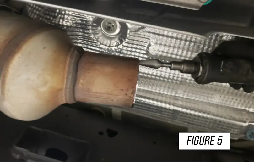
STEP 5
Then use a deburring tool on the cut end of the catalytic converters. It is important that the cut on the catalytic converters are smooth and there are no burs or sharp edges, as shown in Figure 5.
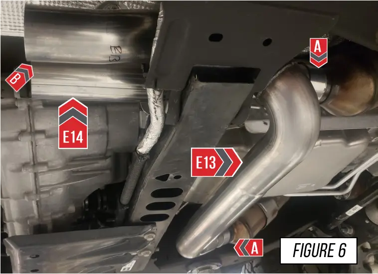
STEP 6
Now install your AWE front sections (E13) and (E14) with a 2.5″ clamp on each inlet section, and install them as shown in Figure 6.
Snug the clamps in place, as shown at (A) in Figure 6.
You want to ensure the outlet of the front sections are parallel, as shown at (B) in Figure 6.
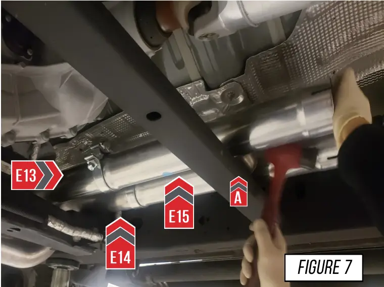
STEP 7
Slide a 3″ clamp on each end of the 2 AWE front sections.
Now put your AWE H-pipe (E15) into place over the chassis brace for proper alignment, as shown in Figure 7. The crossover tube on the H-pipe should be installed over the chassis brace as shown at (A).
Note: If you are unable to get the H-pipe into this position you will need to loosen the ball flange on the front side of the driver side catalytic converter. This will allow you to position the H-pipe correctly. Once desired fitment is achieved tighten the flanges on the catalytic converter.
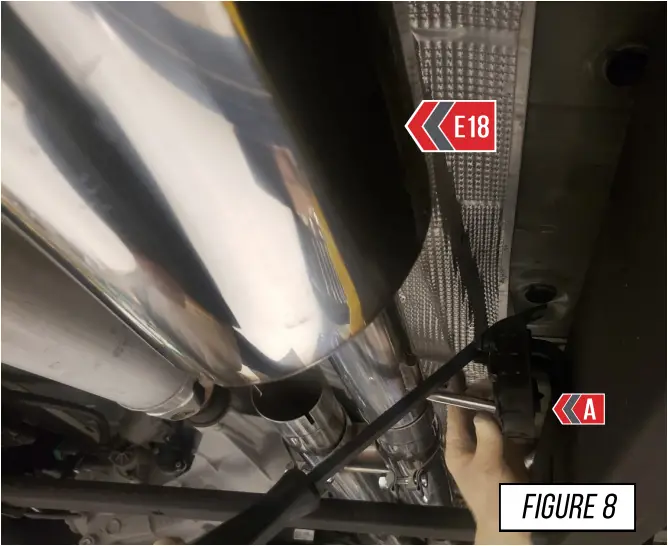
STEP 8
Install your AWE passenger side HR5 section (E18). Slide a provided clamp over the HR5 section, then bottom it in the H-pipe slip fit.
Now rotate the HR5 section so you can slide the hanger bar into the OE rubber hanger, as shown at (A) in Figure 8
Note: Snug the clamp but do not fully tighten it at this point.
Note: It may be helpful to use a pry bar to push the hanger bar into the OE rubber hanger.
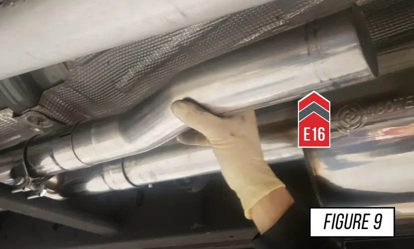
STEP 9
Install your AWE driver side midpipe (E16), bottom out the short side of the midpipe into the slip fit. Then rotate the midpipe so the bend is pointing towards the drive shaft, as shown in Figure 9.
Note: The angle of this tube may need to be adjusted for proper fitment further in the installation. Do not fully tighten the clamp.
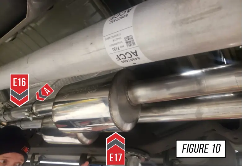
STEP 10
Install your AWE driver side HR5 section (E17), Slide a provided clamp on the HR5 section, then bottom out the HR5 section on the H-pipe slip fit.
Rotate the HR5 section so it is vertical, once the HR5 section is in the correct orientation, snug the clamp on the midpipe (E16), as shown at (A) in Figure 10.
Note: Snug the clamp but do not fully thighten it at this point.
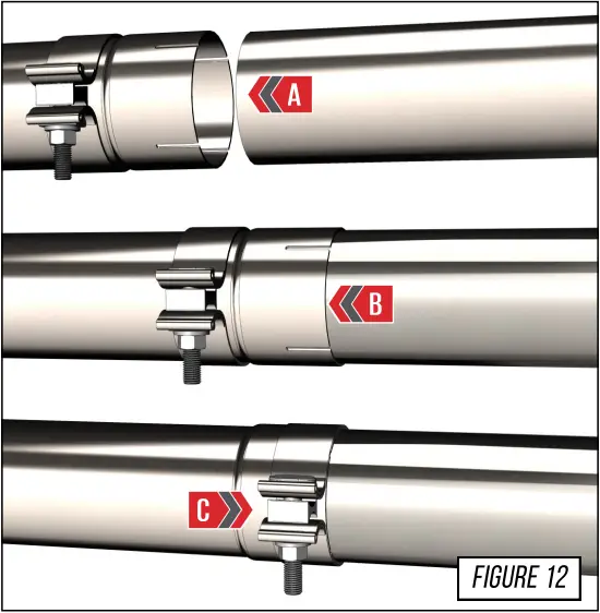
STEP 11
It is crucial to install each section and exhaust band clamps correctly to prevent loose joints, exhaust leaks and rattles.
Arrow A shows the expanded pipe and the preinstalled exhaust clamp being brought up to the corresponding pipe.
Arrow B shows the overlapping pipe installed correctly over the corresponding pipe.
Arrow C shows the exhaust band clamp being brought to the edge of the expanded pipe.
NOTES:
- Do not fully torque any exhaust clamp until the entire exhaust has been installed and adjusted.
- Torque specification is a minimum of 60 ft/lbs
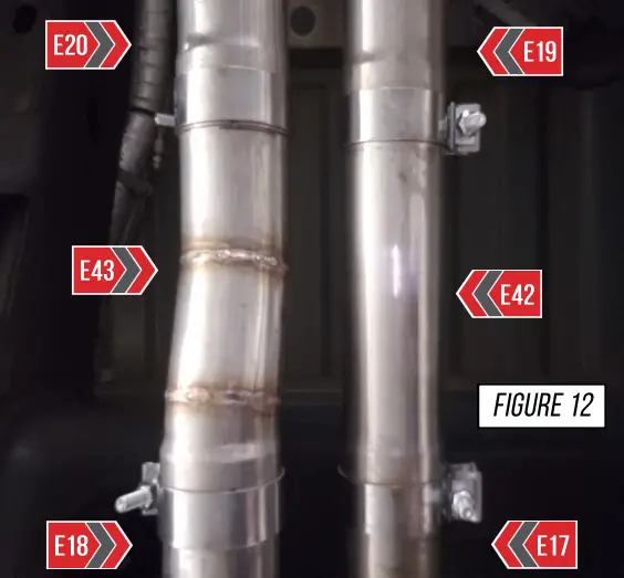
STEP 12
STEP 12 IS FOR LONG WHEEL BASE TRUCKS ONLY
If you have the long wheel base truck, you will need to install the provided long wheel base adapters driver side (E42), and passenger side (E43).
Slide a clamp on each of the preceding HR5 sections, (E17), and (E18). Then bottom out each adapter section, and snug clamps, do not fully tighten them at this time.
The rotation of these adapter tubes may need to be changed to achieve correct fitment.
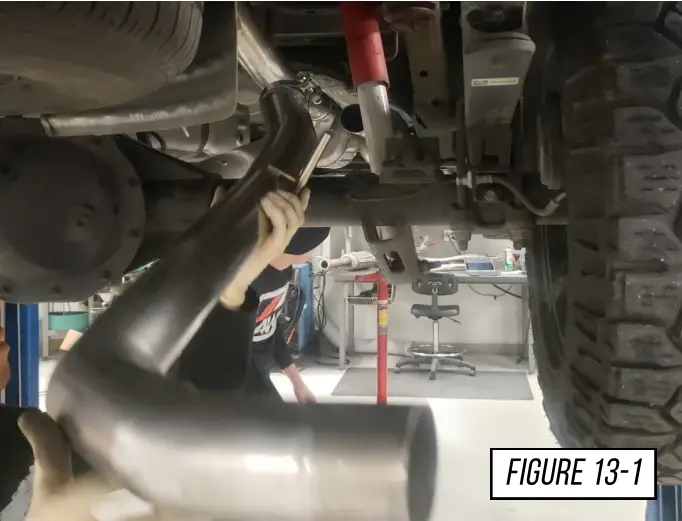
STEP 13
Install your AWE passenger side axle tube (E20), first place the tube over the axle as shown in Figure 13-1.
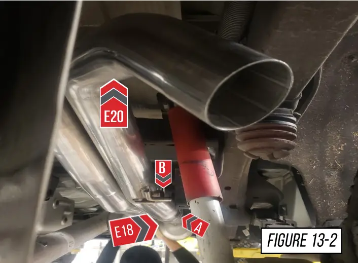
Next slide a provided clamp over the slip joint, and bottom out the slip joint on the HR5 section (E18), as shown at (A) in Figure 13-2. Then rotate the axle tube to slide the hanger bar into the OE rubber hanger (B).
Note: Snug the clamp but do not fully tighten it at this point.
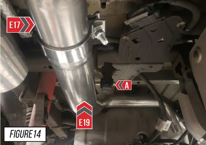
STEP 14
Install your AWE driver side axle tube (E19). Bottom out the slip joint on the HR5 section (E17), rotate the axle tube so you can slide the hanger bar into the OE hanger shown at (A) in Figure 14.
Note: The driver and passenger side axle tubes need to be parallel going over the axle. If you install the driver side axle tube and there is contact with the passenger side axle tube, then there is an adjustments you can make. Rotate your driver side midpipe section (E16) until you have even parallel spacing between the passenger and driver side axle tubes. Once the spacing is achieved snug the clamps down
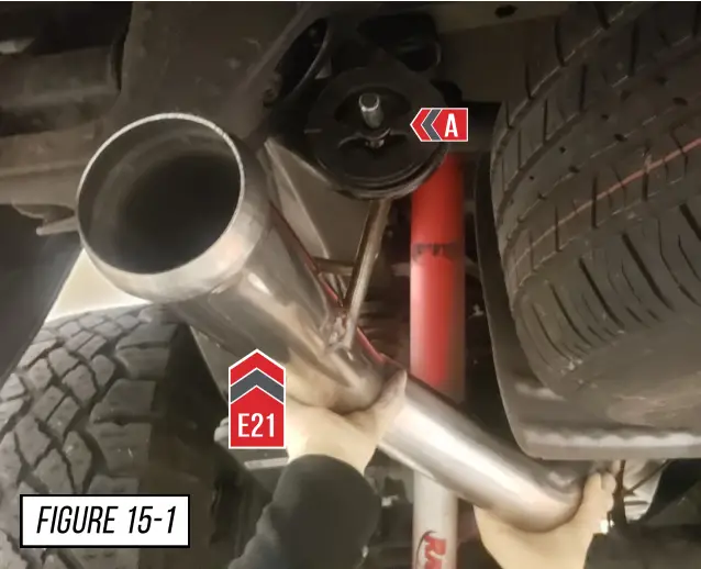
STEP 15
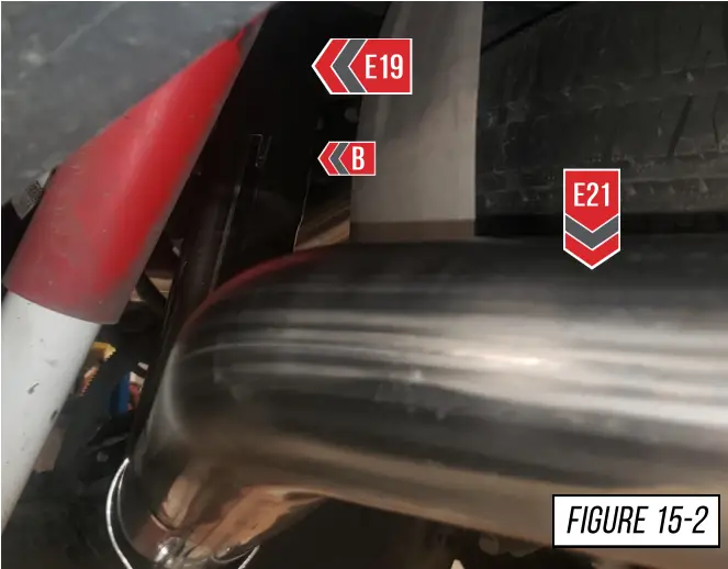
Install your AWE passenger side tailpipe section (E21). First slide the hanger bar into the OE hanger as shown at (A) in Figure 15-1.
Next slide a provided clamp on the slip joint, then bottom out the slip joint on the passenger side axle tube (E19), as shown at (B) in Figure 15-2. Snug the clamp over the joint. Do not fully tighten it at this time.
STEP 16
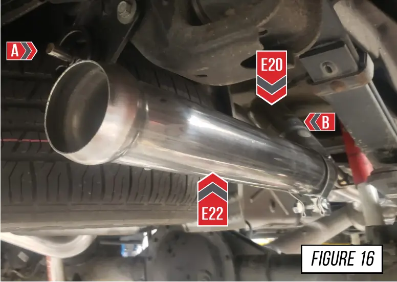
Install your AWE driver side tailpipe section (E22). First slide the hanger bar into the OE hanger as shown at (A) in Figure 16.
Next slide a provided clamp on the slip joint. Then bottom out the slip joint on the driver side axle tube (E20), as shown at (B). Snug a clamp over the joint (B). Do not fully tighten it at this time.
STEP 17
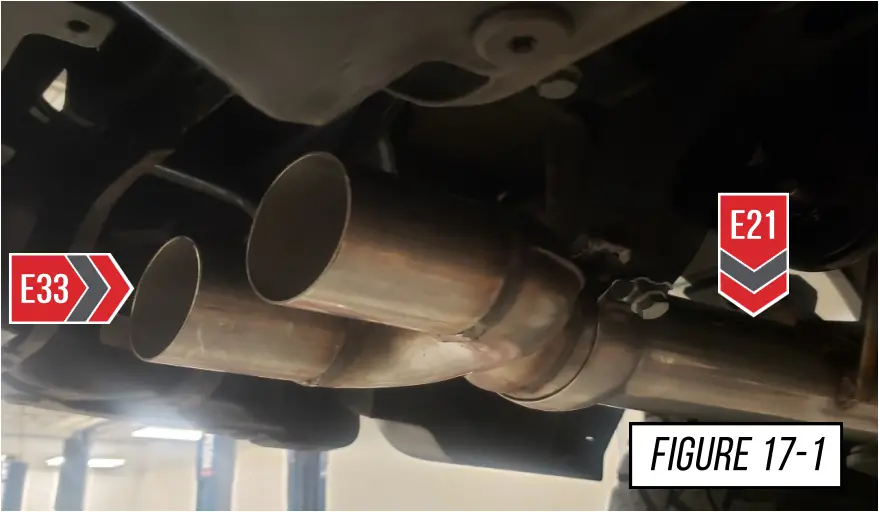
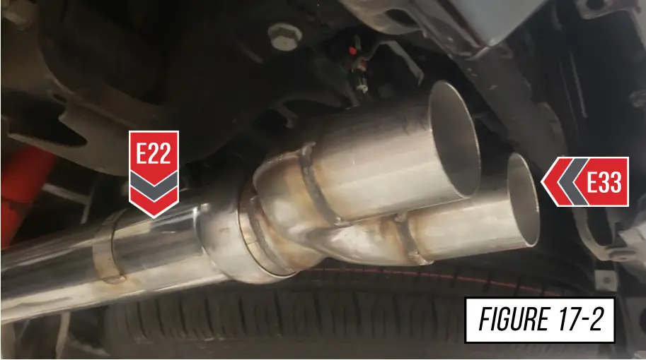
Install your 2 AWE quad tip outlets (E33). Use the provided ball socket clamps to secure the tip outlets, as shown in Figure 17-1, and Figure 17-2.
Note: Do not fully tighten the tip outlet sections, as they may need to be adjusted.
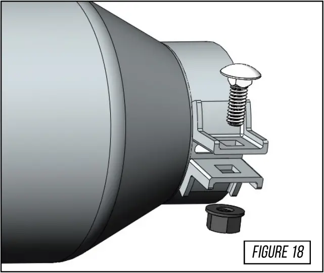
STEP 18
To install the exhaust tips with integrated clamps, first, attach the exhaust tip in the proper orientation onto the exhaust outlet tube.
Insert one of the carriage bolts from the hardware kit (3910-41010) through the tab on the exhaust tip and thread on one of the corresponding nuts.
Using anti-seize on the bolt threads will help installation and prevent breakage of hardware.
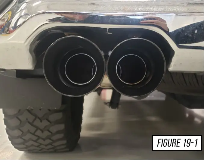
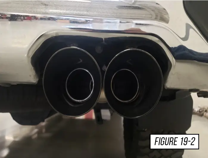
STEP 19
Gather your four AWE exhaust tips, slide them on to the tip outlet sections and orient them so the AWE logo is facing up. Using the provided integrated clamp hardware kit snug the tips down but do not fully tighten to allow for final adjustments.
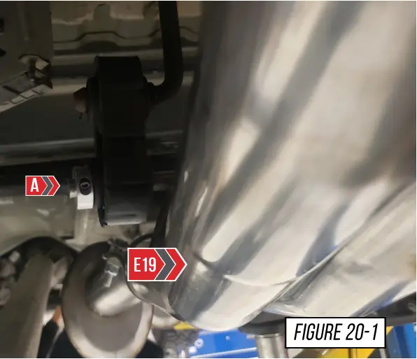
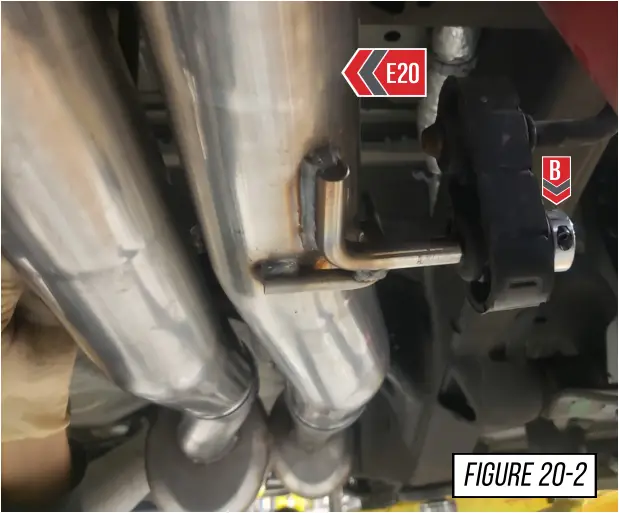
STEP 20
Install the exhaust hanger split collar clamps. Use the included hex wrench to help keep the exhaust system aligned and secure. Install these clamps in the orientation shown at (A) in Figure 20-1, and (B) in Figure 20-2.
STEP 21
Make your final adjustments to the tips to ensure they are in a position you like. Once the desired positioning is achieved, fully tighten down all clamps.
It is now recommended to drive the car to allow the exhaust to heat cycle after all clamps and tips are fully tightened.
At this point the exhaust will be very hot, allow to cool before work continues.
Check the tips for correct alignment, adjust as needed.
Don’t forget to see the next page for any troubleshooting needs!
ENJOY! 
TROUBLESHOOTING
| Issue | Solution |
| Exhaust is not fitting correctly | Most fitment issues are due to improperly adjusted exhaust. This includes tip fitments and rattling due to chassis contact. Check out our fitment guide for more installation tips. |
| Incorrect or missing parts | Double check the parts list for your system and compare them with what you received. Fill out our contact form, found below and let us know what parts you need. |
CARE
Once installed properly, your AWE exhaust will provide years of trouble-free performance.
The exhaust volume and sound will settle with usage; 800-1000 miles is required to break-in new exhaust systems.
Also, please note that the rear 180Technology® resonator has a small drain hole to allow condensation to escape. Water drops from this area are normal.
Periodic cleaning of exhaust tips is necessary to maintain proper finish, especially in areas prone to road salt and caustic deicing solutions. Use a mild soap and water solution or car wax to clean the finish. Avoid using abrasive polishes, as they can scratch the finish.
Any questions or comments, please do not hesitate to contact us:
AWE
215-658-1670
CONTACT FORM
WARRANTY
Up-to-date warranty information is found HERE.
Copyright 2022, AWE. No part of this document may be reused or duplicated without the express permission of AWE. All rights reserved. Rev 1.2


