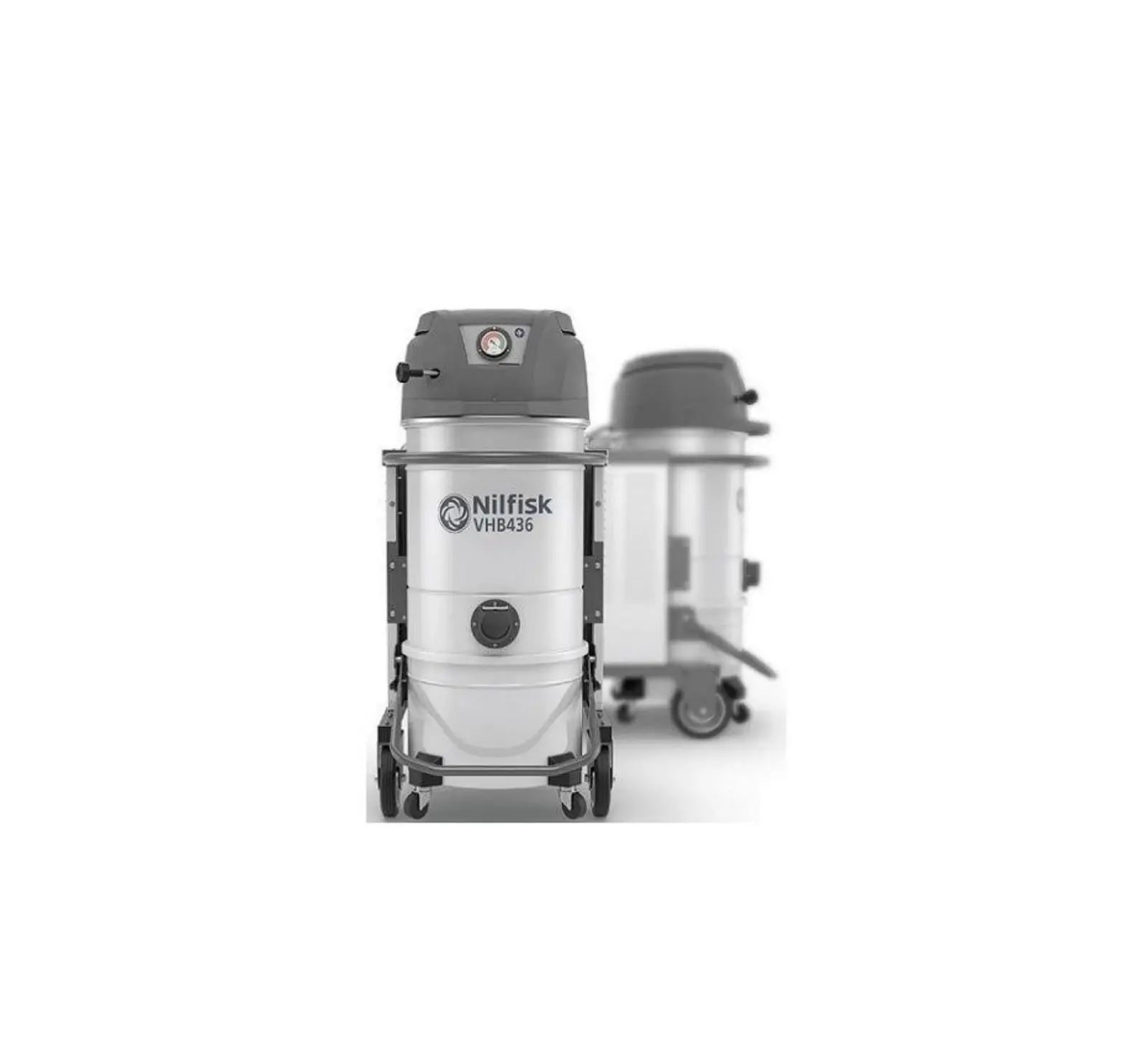
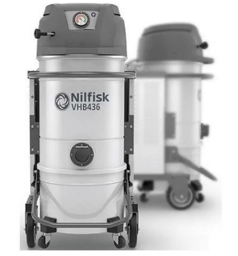
Clemas Co Ltd NILFISK VHB436 Battery Powered Dry Vacuum Cleaner
Instructions for use
Read the operating instructions and comply with the important safety recommendations identified by the word CAUTION!
Operator’s safety
|
 Before starting the machine, it is absolutely essential to read these operating instructions and to keep them on hand for consultation. The machine can only be used by people who are familiar with the way it works and who have been explicitly authorised and trained for the purpose. Before using the machine, the operators must be informed, instructed and trained on how to work it and for which substances its usage is permitted including the safe method for removing and disposing of the vacuumed material.
Repairs must only be carried out when the machine is at a standstill and disconnected from the electricity and air supply mains. Never ever carry out repairs without having first received the necessary authorization. |
General information for using the machine
Use the machine in accordance with the laws in force in the country where it is used.
Besides the operating instructions and the laws in force in the country where the device is used, the technical regulations for ensuring safe and correct operation must also be observed (Legislation concerning environmental and labour safety, i.e. European Union Directive 89/391/EC and successive Directives).
Do not perform any operation that could jeopardize the safety of people, property and the environment.
Comply with the safety indications and prescriptions in this instruction manual.
Proper uses
This machine is suitable for commercial use, in hotels, schools, hospitals, factories, shops, offices and apartment hotels for example, for hire and in any case for purposes other than normal domestic use. This machine is suitable for cleaning and vacuuming solid materials in indoor and outdoor environments.
The machine has been designed to be used by one operator at a time. This machine consists of a vacuum unit, with an upstream filter unit and a container for collecting the vacuumed material.
Improper Use
|
Note: Fraudulent use is not admitted. |
Versions and variations
HEPA variants
This machine can be equipped with an upstream filter (HEPA).
The procedures for servicing and emptying the machine including removing the dust container, must only be performed by authorized personnel wearing protective clothing. Do not use without the complete filter system in place.
General recommendations
Disconnect the machine from the power supply and ask for assistance from qualified personnel. In case the user comes into contact with the vacuumed product, check the cautions shown on the safety technical sheet of the product, which must be made available from the employer. |
Only versions with the level sensor can be used for liquids, if not, they can only be used to vacuum dry materials. |
UN 3481 Please refer to local regulations for their transportation and storage. |
Residual Risks
After carefully considering the risks that are present in all machine operating phases, necessary measures were adopted in order to eliminate the risks for the operators, as far as possible, and/or limit or reduce the risks deriving from hazards that cannot be completely eliminated at the source.
During operations and/or maintenance, operators are exposed to certain residual risks which, due to the nature of the operations themselves, cannot be completely eliminated.
Therefore the installer is responsible for providing additional information and/or hazard signals based on the location of machine installation and the material that is handled.
- Risks due to electrical hazards during maintenance
 Risk of electrocution if accessing the electrical equipment during maintenance without having deactivated the electrical power supply Risk of electrocution if accessing the electrical equipment during maintenance without having deactivated the electrical power supply |
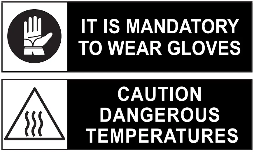
- Risks to the presence of residual high temperature after stopping the vacuum unit.
During maintenance and cleaning operations, the operator may come into contact while the machine is stopped, with parts of the vacuum unit with surfaces at high temperatures.
Specific warning signs placed in strategic points indicate the hazard due to the presence of hot surfaces and the obligation for the user to wear personal protective equipment, in particular protective gloves.
The potentially hot parts (high temperatures) are identified as follows:
EC Declaration of conformity
Every machine comes with a EC Declaration of conformity. See fac-simile in fig. 19.
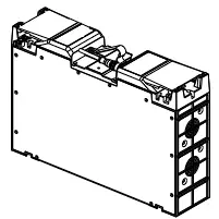
Description of the machine
Machine Parts and Labels
- Identification plate:
Model code, serial number, EC marking, year of manufacture, weight (kg) - Dust container
- Dust container release lever
- Vacuum inlet
- Vacuum gauge
- Filter shaker lever
- Warning plate
Draws the operator’s attention to the fact that the filter must be shaken only when the machine is off (see par. “Shaking the primary filter” as well). - Plug to connect the vacuum cleaner to an electrical outlet for charging.
- Control keyboard
- Closing band
- Electrical connector
This machine creates a strong air flow which is drawn in through the vacuum inlet and blows out through the outlet.
Before turning on the machine, fit the vacuum hose into the inlet and then fit the required tool on to the end part (refer to the manufacturer’s accessory catalogue or Service Centre).
The diameters of the authorized hoses are indicated in the Technical data table.
The machine is equipped with a primary filter which enables it to be used for the majority of applications.
In addition to the primary filter that retains the most common dust, a secondary filter (absolute filter) can be installed.
This machine is equipped with an internal baffle plate which subjects the vacuumed substances to a circular centrifugal movement that makes them drop into the container.
Optional kits
Various optional kits are available for converting the machine.
On request, the machine can be supplied with optional kits already installed. However, they can also be installed at a later date.
Please contact the sales network for further details.
Instructions describing how to fit the optional kits and the relative operation and maintenance manuals are supplied together with the optional kits.
|
Accessories
Various accessories are available; refer to the manufacturer’s accessory catalogue.
|
Packing and unpacking
All the dispatched equipment has been thoroughly checked before being delivered to the haulage contractor. On arrival, check the machine to see that it has not been damaged during transport. In case of damage, immediately lodge a complaint with the haulage contractor.
Dispose of the packing materials in compliance with the laws in force.
Figure 3
| Model | A (mm) | B (mm) | C (mm) | kg (*) |
| VHB436 | 1200 | 700 | 1700 | 150 |
(*) Weight with packing
Unpacking, moving, use and storage
To unpack the vacuum unit, remove the retainers with a hammer and a screwdriver.
Also remove the fastening devices placed by the manufacturer when packing, by using suitable tools.
Release the wheel brakes and remove the machine from the supporting platform, by using a ramp that can provide adequate
capacity, and by driving the vacuum cleaner by the handle.
Operate on flat, horizontal surfaces. The load-bearing capacity of the surface the machine is placed on must be suitable for bearing its weight.
If the device is to work in a fixed position, allow wide space around the device in order to ensure freedom of the movement and allow the maintenance staff to operate with ease.
Commissioning
|
The system safety officers must:
- Prevent any improper use or manoeuvre.
- Make sure that the safety devices are not removed or tampered with.
- Check that all maintenance operations are regularly performed;
- Make sure that no machine part (couplings, holes, etc.) is modified to attach additional devices;
- Make sure that only original Nilfisk spare parts are used.
NOTE The user shall be responsible for ensuring that installation complies with the all relevant local provisions. The equipment must be installed by qualified technicians who have read and understood the instructions herein. |
Charging method
|
|
Do not use water to clean the battery module. Never place containers with liquids (beverage containers and the like) on electrical equipment. The relative humidity inside the room should not exceed 85%. Do not clean the system with agents containing acid, caustic soda, or solvents. |
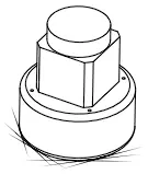
Charging the machine
Figure 1
To charge the machine battery, connect the supplied power cable to the plug (8). The charging LED starts flashing and charging is in progress
Dry applications
Technical data
| Parameter | Units of measurement | VHB436 | |
| 2 Battery (Standard) | 3 Battery (Optionals) | ||
| Voltage | V | 36 | |
| Power rating | kW | 2,4 | |
| Current | Amp | 60 | |
| Max vacuum | mm H20 | 1300 | |
| Maximum air flow rate without hose and reductions | L/m’ | 7050 | |
| Maximum air flow rate (3 m Ø 50 mm hose) | L/m’ | 4833 | |
| Sound pressure level (Lpf) (EN60335-2-69) (*) | dB(A) | 71 | |
| Vibration, ah (**) | m/s2 | ≤2,5 | |
| Insulation | Class | III | |
| Container capacity | L | 50 | |
| Longopac® dust bag capacity | L | – | |
| Vacuum inlet (diameter) | mm | 70 | |
| Allowed hoses | mm | 50 | |
| Primary filter surface | m2 | 1,95 | |
| Upstream H absolute filter surface | m2 | 3,50 | |
| Absolute filter efficiency according to MPPS method (EN 1822) | % | 99,995 (H14) | |
| Operating time | min | 98 | 146 |
| Charging time | min | 200 | 270 |
| Weight | kg | 125 | 135 |
(*) Measurement uncertainty KpA < 1.5 dB (A). Noise emission values obtained according to EN 60335-2-69
(**)Total value of vibration output to the operator arm and hand
Dimensions
Figure 3
| Model | VHB436 |
| A (mm) | 1050 |
| B (mm) | 600 |
| C (mm) | 1250 |
|
| When used at temperatures below 0°C, battery life may not be as stated. |
Controls and indicators
Figure 4
- Start/stop switch
If the indicator is ON, the motor is ON.
You can start/stop each motor with this button. - Stop button
When this button is pressed, all motors stop at the same time. - Battery charge indicator
When all LEDs are ON, the battery is fully charged. - Manual filter shaker knob
Inspections prior to starting
Figure 5
- Vacuum inlet
Before starting, check that:
- The filters are installed.
- The closing band is properly tightened.
- The vacuum hose and tools have been correctly fitted into the vacuum inlet (1).
- The bag or safety container is installed, if applicable.
Starting and stopping
Figure 4
- Press the button (2) to start each vacuum motor
- Press the button (1) to start each additional vacuum motor
- Press the button (1) again to stop each motor or press the button (2) to stop all motors at the same time.
Emergency stopping
Press the Stop button. The vacuum cleaner stops.
Operation
Figure 6
Vacuum gauge (2): green zone (3), red zone (1)
When using the machine, check the flow control:
- when the machine is operating, the pointer of the vacuum gauge must remain in the green zone (3) to ensure that the speed of the intake air does not drop below the safety value of 20 m/sec;
- If the pointer is in the red zone (1) it means that the speed of the air in the vacuum hose is less than 20 m/s, and that the machine is not operating in optimal conditions. Shake or replace the filter.
- during normal operation conditions, close the vacuum hose, the pointer of the vacuum gauge must switch from the green zone (3) to the red zone (1).
Consult the “Troubleshooting” chapter if faults occur. |
Condition indicated by the vacuum gauge pointer in the green zone (3). |
At the end of a cleaning session
- Turn off the machine.
- Empty the container and clean the machine as described in the “Maintenance, cleaning and decontamination” paragraph.
- Wash the container with clean water if aggressive substances have been vacuumed.
- Store the machine in a dry place, out of reach of unauthorised people.
- Lock the castor brakes.
- During transport and when not using the machine, close the vacuum inlet with the relevant plug (if equipped).
Maintenance, cleaning and decontamination
Failure to comply with these instructions could jeopardize your safety. Moreover, such action would immediately void the EC declaration of conformity/ incorporation issued with the machine. |
- To allow the user to carry out the maintenance operations, the machine must be disassembled, cleaned and overhauled as far as is reasonably possible, without causing hazards for the maintenance staff or other people. The suitable precautions include decontamination before disassembling the machine, adequate filtered ventilation of the exhaust air from the room in which it is disassembled, cleaning of the maintenance area, and suitable personal protection.
- The external parts of the machine must be decontaminated by cleaning and vacuuming methods, dedusted or treated with sealant before being taken out of a hazardous zone.
- All parts of the machine must be considered as contaminated when they are removed from the hazardous zone and appropriate actions must be taken to prevent dust from dispersing.
- When maintenance or repair procedure are carried out, all the contaminated elements that cannot be properly cleaned, must be eliminated.
- These elements must be disposed of in sealed bags in accordance with applicable regulations and local laws on the disposal of such material.
- This procedure must also be followed for filter disposal (primary and absolute filters).
- Compartments that are not dust-tight must be opened with suitable tools (screwdrivers, wrenches, etc.) and thoroughly cleaned.
- A check must be carried out by the manufacturer or the personnel of the same at least once a year. For example:
Check the air filters to find out whether the air-tightness of the machine has been impaired in any way and make sure that the electric control panel operates correctly
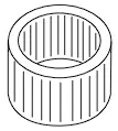
Primary filter cleaning with manual system
Figure 7
In relation to the quantity of material vacuumed and if indicator (2 – Fig. 6) is red, turn the vacuum cleaner off and use knob (1) of the manual filter shaker.
Do not shake the filter with the machine functioning, as this could damage the filter. |
Wait before restarting the machine, to allow the dust to settle.
Replace the filter element if the indicator is red, even after the filter has been shaken (see “Primary and absolute filters disassembly and replacement”)
Clean these parts if this is the case. |
Emptying the container
Check the machine filtration class. |
Before emptying the container it is advisable to clean the filter (see “Cleaning the primary filter” paragraph).
Figure 8
- Release the dust container with lever, then remove andempty it.
- Clean the machine as described in the “Maintenance, cleaning and decontamination” paragraph.
- Wash the container with clean water if aggressive substances have been vacuumed.
- Make sure the gasket is in perfect condition and correctly positioned.
- Place the container back in position and secure it again.
Avoid switching on/off too frequently. |
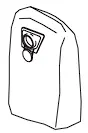
Dust Bag
Figure 8
The machine can be equipped with dust collection bag.
In this case, the machine must be equipped with optionalaccessories (depressor and grid).
If the bag is not installed or is installed improperly, it couldcreate health risks for people exposed.
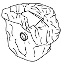
Paper Bag and Safe Bag for dust collection
Figure 9
The machine can be equipped with dust collection bag.
In this case, the machine must be equipped with a specific container and a cap on the side.
If the bag is not properly installed, it could create health risks for people exposed.
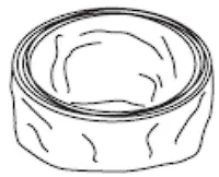
Longopac® bag for dust collection
Figure 10
The machine can be equipped with dust collection bag.
In this case, the material is discharged by gravity when the vacuuming stops. The Longopac® bag can be cut, sealed or closed to the size required.
If the bag is not properly installed, it could create health risks for people exposed.
Replacement of dust bags
|
How to replace the Dust Bag
Figure 8
- Close the inlet by using the relevant cap (if equipped).
- Release the dust container.
- Remove the dust bag and close it with a clamp, if necessary.
- Place a new bag, taking care to wrap it around the outer wall of the dust container.
- Set the dust container into the machine again.
How to replace the Paper Bag
Figure 9
- Close the inlet by using the relevant cap (if equipped).
- Release the dust container.
- Remove the bag and close it with the relevant cap (1) as shown in the figure.
- Insert a new bag, making sure the bag inlet is sealed.
- Set the dust container into the machine again.
How to replace the Safe Bag
Figure 9
- Remove and put the vacuum hose in a safe and dust-freeplace.
- Close the inlet by using the relevant cap (if equipped).
- Release the dust container.
- Close the Safe Bag by pulling the “guillotine” seal (2).
- Close the plastic bag hermetically using the relevant band (3).
- Use the sticky tape (4) to close the bottom of the plastic bag.
- Remove the relevant connection (5) of the bag from the inlet.
- Insert a new safe bag, making sure the vacuum inlet is well connected to the bag attachment, to grant the sealing.
- Wrap the plastic bag around the dust container external wall.
- Place the dust container in the vacuum cleaner
How to replace the Longopac®
Figure 10
- Turn the bag full of dust (1) on itself to obtain a section of coiled bags to be tightened with two clamps (2).
- Place the two clamps at a distance of 50 mm between them, then with a pair of scissors cut between the two clamps.
- Remove the bag full of dust (1) and place the new sectionof Longopac® (3).
Main and absolute filter disassembly and replacement
|
Otherwise the machine will not operate correctly. Before proceeding with these operations, turn off the machine and remove the plug from the power socket. |
Primary filter replacement, for machines equipped with manual cleaning system
Figure 11
- Disengage the electrical connector.
- Remove the vacuum hose (1).
- Use the lever (2) to remove the cover (3) together with the primary filter.
- Remove the old filter from the cage.
- Dispose of the old filter according to the laws in force.
- Fit the new filter and insert the cage.
- Install the cover and the primary filter in the reverse order of removal.
Upstream absolute filter replacement
Figure 12
- Loosen the clamp with a screwdriver and remove the vacuum hose (1).
- Unscrew the knob (2).
- Unlock the safety bolt (5).
- Use the lever (4) to release the cap (3) then pull it up and out of the vacuum cleaner.
- Unscrew ring nut (6)
- Pull out fastening disc (7) and absolute filter (8)
- Place absolute filter (8) in a plastic bag, close the bag hermetically and dispose of the filter in accordance with the laws in force.
- Insert a new filter (8) with the same filtering characteristics as the removed one
- Lock the absolute filter with disc (7) and tighten the ring nut (6)
- Insert the cap (3) again.
- Fix the cap in place with the lever (4) and lock the safety bolt (5) again.
- Screw the knob (2).
- Fit the vacuum hose (1) back in place and tighten the clamp
- Lock it retightening the four nuts (1).
Downstream absolute filter replacement
- Unscrew the knob and remove the cover.
- Remove the absolute filter and place it in a plastic bag, close the bag hermetically and dispose of the filter in accordance to the laws in force.
- Insert a new absolute filter with the same filtering characteristics as the removed one.
- Reinstall the cover by fastening it with the knob.
Installation, cleaning and replacement of the separator (optional)
Figure 13
The separator (4) should first be disassembled in order to be perfectly cleaned:
- Release the closing hooks (1) of the cover (2) and remove the cover.
- Remove the filter.
- Unscrew the two screws (3) and remove it from the container.
- Replace the part if it is excessively worn.
- Reinstall the separator (4).
- Lock it and fix it by means of the two screws (3).
- Fit the filter back in place, close the cover (2) and lock it by means of the two the closing hooks (1).
Tightness inspection
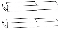
Hoses check
Figure 14
Make sure that connecting hoses (1) are in a good condition and correctly fixed.
If the hoses are damaged, broken or badly connected to the unions, they must be replaced.
When sticky materials are treated, check for possible clogging along the hose, in the inlet and on the baffle plate inside the filtering chamber.
To clean, scrape the inlet (2) from the outside to remove deposits.
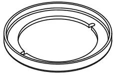
Filtering chamber gasket check for machines equipped with dust container
Figure 15
If the gasket (1) between the container and the filtering chamber (3) fails to guarantee sealing:
- Loosen the four screws (2) that lock the filtering chamber (3) against the machine structure.
- Allow the filtering chamber (3) to lower down and tighten the screws (2) once it has reached the sealing position.
If an optimal seal is not yet obtained or if there are tears, cracks, etc., the gasket must be replaced.
Filtering chamber gasket check for machines equipped with Longopac® system
Figure 16
Ensure that the Longopac® bag is tight with the gasket (2).
Also check the seal of the gasket positioned on the discharge clapet (1).
The gasket must be replaced if it is torn, cut, etc…
Disposal
Figure 17
The crossed-out wheeled bin symbol on the equipment indicates that used electrical and electronic equipment must be collected and disposed of separately from household waste. The correct disposal of the equipment will help prevent potential negative consequences for the environment and human health.
Electrical and electronic household equipment must be disposed of at the separate collection points in the residence area. Please note that commercial electrical and electronic equipment should be disposed of separately from the municipal waste stream. We will be pleased to inform you about suitable disposal options.
Wiring diagrams
Figure 18
Recommended spare parts
The following is a list of spare parts that should be kept ready at hand in order to speed up maintenance operations.
Refer to the manufacturer’s spare parts catalogue when ordering spare parts
| Name | Model | |
 | Star filter kit | 40000492 |
 | Filter ring gasket | Z8 17026 |
 | Filter chamber gasket | 4081701540 |
 | Filter clamp | Z8 18079 |
 | Absolute filter | 4081700935 |
 | Longopac | 4084000956 |
 | Paper Bag – Dust bag (5 bags) | 81584000 |
 | Safe Bag (1 bag) | 4084001468 |
 | LDPE polyethylene bag | Z8 40099 |
 | 36V motor | 4089101116 |
 | Motor brush | 4083902036 |
 | Motor gasket | Z8 17325 |
 | Battery kit | 106479011 |
Troubleshooting
| Problem | Cause | Remedy |
| The machine does not start | Battery issues | Check if the battery is sufficiently charged. Check whether the LED on the battery is green. Check the status of the socket and the charging cable. Ask for assistance to be performed by a qualified manufacturer’s technician. |
| The machine revolutions increase | Clogged primary filter | Use the filter shaker (models with manual filter shaker). Replace it if this is not sufficient. |
| Clogged vacuum hose | Check the vacuum hose and clean it. | |
| Dust leaks from the machine | The filter is torn | Replace it with another of identical type. |
| Inadequate filter | Replace it with another of a suitable category and check. | |
| Electrostatic current on the machine | Missing or inefficient grounding | Check all ground connections. In particular on the vacuum inlet fitting; replace the hose with an antistatic hose. |
Clemas & Co. Unit 16 Ashchurch Business Centre, Alexandra Way, Tewkesbury, Gloucestershire, GL20 8NB.
Tel: 01684 850777 Fax: 01684 850707
Email: [email protected] Web: www.clemas.co.uk