SENVA EMX True RMS Energy Meter
![]() HAZARD OF ELECTRIC SHOCK, EXPLOSION, OR ARC FLASH
HAZARD OF ELECTRIC SHOCK, EXPLOSION, OR ARC FLASH
Failure to follow these instructions may cause serious injury or death
- Do not use this product for life safety applications.
- Do not install this product in hazardous or classified locations.
- Only qualified trade installers should install, program, maintain and test system incorporated therein. Installer is responsible for compliance of all applicable codes.
- Read, understand, and follow instructions thoroughly.
- The Standard CTs associated with this product must be mounted inside a suitable fire and electrical enclosure. For safe electrical work practices, see NFPA 70E in the USA or applicable local standards and codes.
- Replace all doors, covers, and protective devices before powering the equipment.
- Product may use multiple voltage/power sources. Disconnect ALL sources before servicing.
- Use a properly rated voltage sensing device to confirm that power is off. DO NOT depend on this product for voltage indication.
- The installer is responsible for conformance to all applicable codes.
- For use with Listed Energy Monitoring Current Transformers.
- Use Copper Conductors Only
- Per IEC 61010-1 section 8.2.2 “impact test”, this product tested with energy of 2J (reduced from 5J) code: IK07
 Failure to follow these instructions may cause injury, death or equipment damage.
- If product is used in a manner not specified by the manufacturer, the protection provided by the product may be impaired. No responsibility is assumed by the manufacturer for any consequences arising out of the use of this material.
LIMITATION OF LIABILITY
Senva’s liability, whether in contract, in tort, under any warranty, in negligence or otherwise shall not exceed the amount of the purchase price paid by the purchaser for the product. Under no circumstances shall Senva be liable for special or consequential damages.
FEATURES
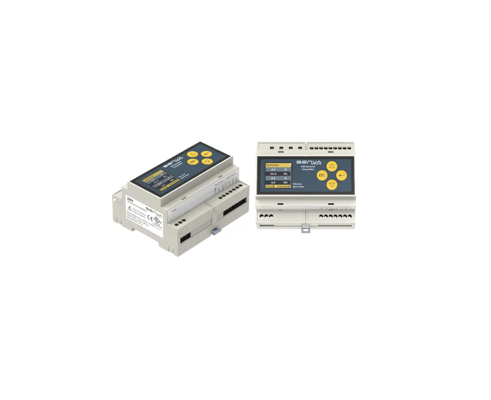
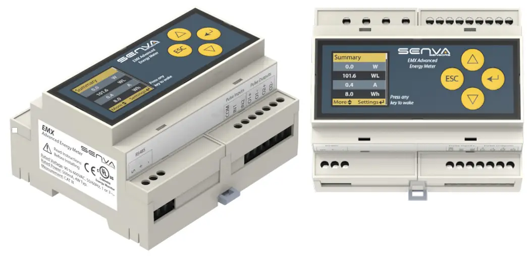
The Senva EMX Advanced Energy Meter is a 3 channel True RMS energy meter featuring a color OLED display for simple commissioning and monitoring. The EMX meets ANSI C12.20 Class 0.2 Standards. The EMX supports both BACnet MS/TP and Modbus RTU protocols and also includes 2 pulse inputs and 2 pulse outputs.
The EMX supports metering CTs with either a 0.333V voltage output or di/dt signal. The EMX is a class 2 low voltage device for mounting flexibility. See Specifications section for recommended conductor gauge and terminal tightening torque.
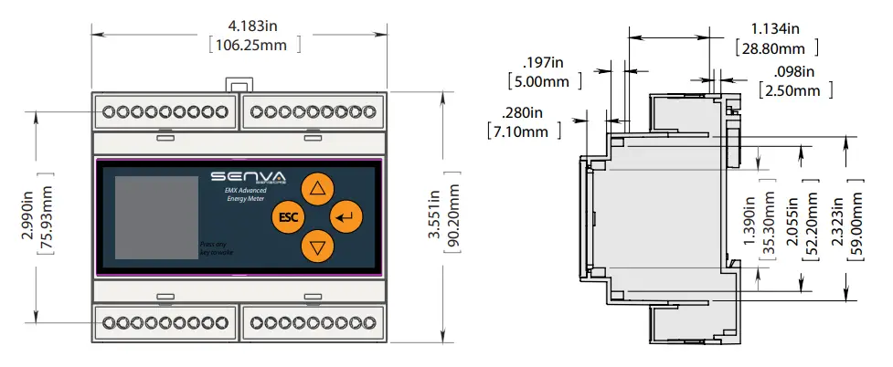
MOUNTING
The Senva EMX Advanced Energy Meter is suitable for installation on T35 DIN rail. Simply place unit approximately centered over the mounted DIN rail and press upward until the bottom clicks into place. Using a flat-nose screwdriver, pull top tab and apply pressure downward until unit is flush and release the tab. See Dimensions section for details.
DIMENSIONS
WIRING
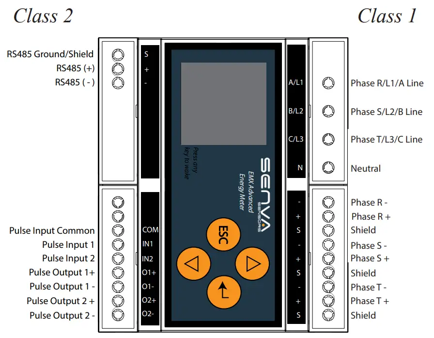
EMX Wiring
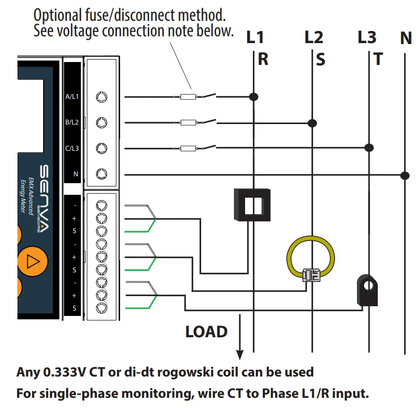
Using Traditional metering CTs please wire according to the following diagram.
![]() Wiring for connections labeled “Class 2” shall be permanently separated from those labeled “Class 1” by a minimum of 6 mm by means of clamping, routing, or equivalent means.
Wiring for connections labeled “Class 2” shall be permanently separated from those labeled “Class 1” by a minimum of 6 mm by means of clamping, routing, or equivalent means.
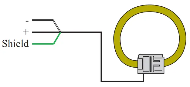
Typical Metering CT Wiring
A compatible metering CT has either a 0.333V voltage output or di/dt signal. The wiring shown below corresponds to a Senva Metering CT and may not represent the coloring for all compatible CTs.
![]() WARNING: To reduce the risk of electric shock, always open or disconnect circuit from power distribution system (or service) or building before installing or servicing current transformers.
WARNING: To reduce the risk of electric shock, always open or disconnect circuit from power distribution system (or service) or building before installing or servicing current transformers.
Current transformers are not suitable for Class 2 wiring methods and not intended for connection to Class 2 equipment.
Field installed current transformers can be installed in panel boards or switch gear enclosures and shall be installed according to the following:
- Always open or disconnect circuit from power-distribution system (or service) of building before installing or servicing current transformers.
- The current transformers may not be installed in equipment where they exceed 75 percent of the wiring space of any cross-sectional area within the equipment.
- Restrict installation of current transformer in an area where it would block ventilation openings.
- Restrict installation of current transformer in an area of breaker arc venting.
- Secure current transformer and route conductors so that they do not directly contact live terminals or bus.
TYPICAL 3Ø WIRING 120 to 600VAC
Voltage Wiring
UL 240.21 code permits qualified installers to forgo use of a disconnect device (fuses or circuit breakers) when connecting the voltage reference of the CT, as long as the tap does not exceed 10 feet and complies with additional guidelines regarding ampacity rating, enclosure spacing and point of connection. It is the responsibility of the installer to ensure the system meets the requirements of the UL 240.21 code.
If the installation does not conform with the UL 240.21 code or the voltage reference must be extended beyond 10 feet, proper use of over current protection is required (i.e., fusing or circuit breakers.)
In the U.S. and Canada, disconnecting fuse holders or circuit breakers can be used. Place this device in close proximity to the CT and within easy reach of the operator, and mark it as the disconnecting method. The disconnect shall meet the relevant requirements of IEC 60947-1 and IEC 60947-3 and shall be suitable for the application. Provide over-current protection and disconnecting method for supply conductors with approved current limiting devices suitable for protecting the wiring.
OPERATION
Once power is applied to the unit, the OLED screen will display the summary screen for a single load meter. To review more system measurements, the up and down arrows will cycle between the summary page, power readings, amperage readings, and voltage readings.
Power Setup
To set up the meter for the correct circuit, press the enter button ![]() to enter the Metering Menu. The connection type 3-phase ABCN or ABC and 1-phase ABN or AB must be selected via menu, this must correspond to the wiring method used.
to enter the Metering Menu. The connection type 3-phase ABCN or ABC and 1-phase ABN or AB must be selected via menu, this must correspond to the wiring method used.
Wiring Config: Press enter ![]() to choose between single circuit or multi-circuit.
to choose between single circuit or multi-circuit.
RS485 setup
The EMX is designed to easily connect to an existing communication network. To configure the network baud rate, protocol type, serial formats, and self-address (BACnet only), press the enter button and scroll down ![]() to access the Communication Menu. Here you can set the following:
to access the Communication Menu. Here you can set the following:
- Protocol: Press enter to choose between BACnet MS/TP or Modbus RTU.
- Device Address: Press or hold enter to increase address
- Baud Rate: Press enter to choose between 9600, 19200, 38400, 57600, 76800, and 115200.
- Parity: Press enter to choose between none, even, and odd
- Stop Bits: Press enter to choose between 1 and 2.
If any alarm is present, a red exclamation mark will appear in the top right corner of the OLED. At any time during normal operation, user may scroll to the alarm menu to view active or previous alarm conditions. See Troubleshooting section for diagnostics.
TROUBLESHOOTING
See below table to diagnose alarms present on EMX.
| Power Alarms | Corrective Action |
| Negative power | Verify CT orientation toward load. |
| Phase Loss | Check all phase voltages and current. |
| Low PF | Sensor is reading PF<0.5. If not low PF, ensure voltage legs match with CTs. |
| Freq out of range | Frequency is below the minimum 45Hz or above the maximum 65Hz. |
| Voltage out of Range | Ensure system voltage does not exceed 600VAC. |
| Current out of Range | Replace with a larger amperage rated CT. |
| Neutral Current out of Range | Ensure desired voltages are being Monitored. |
| Frequency Deviation | Verify the settings for the nominal frequency and the threshold in the alarm menu. |
| Voltage Phase Loss | No dected voltage on one of more phases. |
| Pulse Config Error | Verify settings and consider increasing the Wh per pulse setting. User selected pulse settings violated the maximum duty cycle of the pulse output (50%), and the pulse duration setting was adjusted down by the firmware. |
| Pulse overrun error | Verify pulse settings and consider increasing the Wh per pulse, or decreasing the pulse duration. |
If code is not shown in table above, please contact Senva technical [email protected] or (866) 660-8864
BACnet/Modbus Quick Reference
The following section outlines some commonly utilized Modbus registers and BACnet objects for quick reference. For a complete list and description of each, please see the associated protocol guides: EM-RS485 BACnet Protocol Guide or EM-RS485 Modbus Protocol Guide.
| Description | BACnet Object | Modbus Register | Unit |
| L-N Average RMS Voltage | AI1 | 1 | Vrms |
| L-L Average RMS Voltage | AI2 | 2 | Vrms |
| Average RMS Current | AI3 | 3 | Arms |
| Total Real Power | AI5 | 5 | W |
| Total Reactive Power | AI6 | 6 | VAR |
| Total Apparent Power | AI7 | 7 | VA |
| Total Real Energy | AI8 | kWh | |
| System Power Factor | PF | ||
| R/S/T Phase RMS Voltage | AI11/12/13 | 8/9/10 | VrmsLN |
| RS/ST/TR Line RMS Voltage | AI14/15/16 | 11/12/13 | VrmsLL |
| R/S/T Phase RMS Current | AI17/18/19 | 14/15/16 | Arms |
| R/S/T Phase Power Factor | AI20/21/22 | 17/18/19 | PF |
| R/S/T Phase Real Power | AI24/25/26 | 21/22/23 | W |
| R/S/T Phase Real Energy | AI33/34/35 | kWh | |
| Pulse Input 1 | AI40 | # | |
| Pulse Input 2 | AI41 | # |
Supported Modbus Functions:
0x03 Read Holding Registers
0x06 Write Single Register
0x10 Write multiple Registers
SPECIFICATION
| Power Supply Input | Line/High voltage mode Power Consumption Frequency Range | l 90-600VLL (+20%), 50/60Hz, 1-3 phase 4W Typ. 50/60 Hz |
| Output | RS-485 Baud Rates RS-485 Loading | 2-wire, BACnet MS/TP, Modbus RTU, Modbus ASCII 9600, 19200, 38400, 57600, 76800, 115200 1/4 unit |
| Pulse Output | Dual Outputs Type Alarm Configuration Ratings Pulse scaling Duration | Import & Export Energy Outputs, Alarm Status, and Pulse Input Echo Solid state dry contact N.O. or N.C. 40VAC/DC, 300mA Max 0.01, 0.1, 1, 10, 100, 1k Wh/Pulse 10, 25, 50, 100, 250, 500 (ms) |
| EMX Wiring Requirements | Conductor gauge Terminal torque rating | 12-24 AWG; Power terminals: 12-18 AWG 0.37 ft-lb (0.50 N•m) |
| Pulse Inputs | Input Rating Pulse Active Pulse Undefined Pulse Idle Puse Length | 3.5 ± 0.5 VDC, short circuit current is 10mA max <10 kOhms 10-30 kOhms >30 kOhms Accepts Pulses >10ms Rejects Pulses < 5ms |
| Service Types | Configurations Voltages Frequency Measurement | 1Ph, 2Ph, 3Ph Wye (4-Wire), 3Ph Delta (3-Wire) 90VL-N through 600VL-L 45-65 Hz CAT III |
| EMX Performance | Meter Accuracy State System Accuracy | 0.2% (ANSI C12.20 Class 0.2 standards), True RMS Meets WA State Clean Building Bill 1% for V, A, kW, kVAR, kVA |
| Operating Environment | Operating Temperature Storage Temperature Humidity Environmental Rating | -22 to 158ºF (-30 to 70ºC) -40 to 185ºF (-40 to 85ºC) 0-95% non-condensing IP20; Front display IP40 |
| EMX Meter Enclosure | Material Dimensions | Polycarbonate/ABS 3.55”h x 4.18”w x 2.26”d |
| Compliance | Agency Standards | UL Listed, cUL Listed, File E489498 CE, RoHS |