elma instruments 6100EVSE True RMS Multimeter User Manual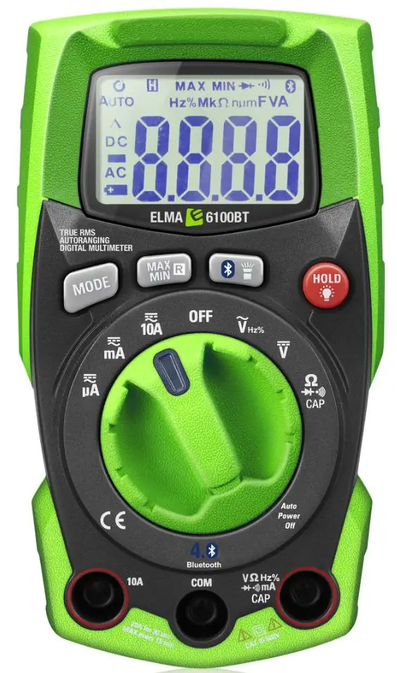
Introduction
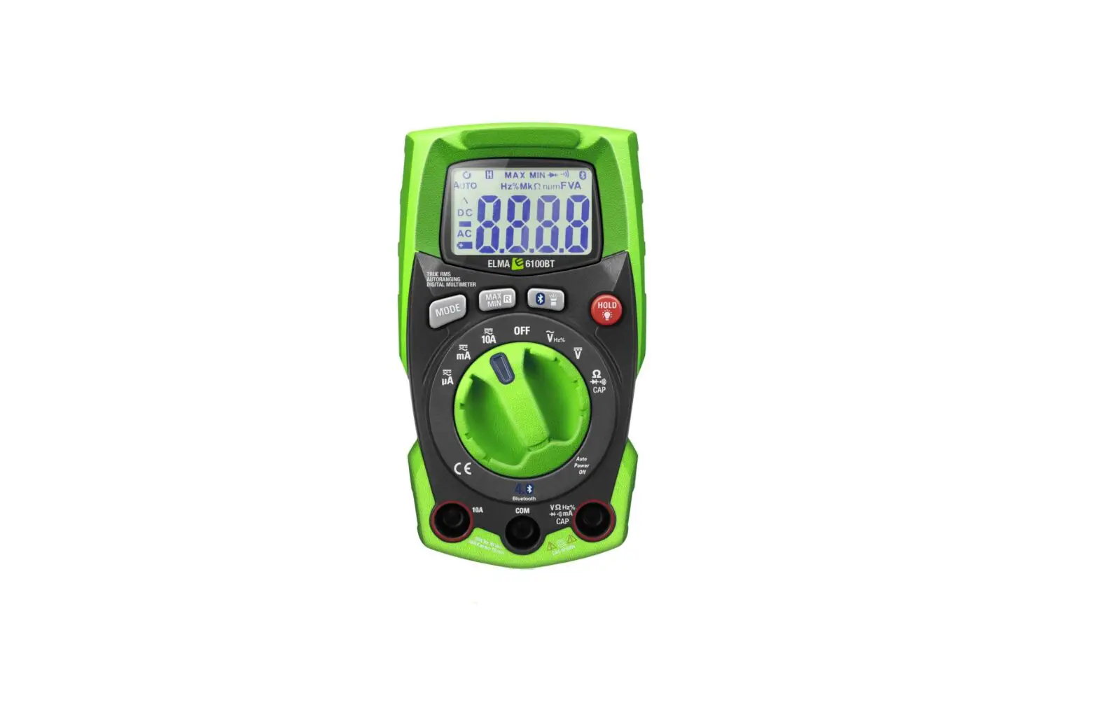
Instructions for Elma 6100EVSE multimeter.
Elma 6100EVSE is a robust TRUE RMS AC / DC multimeter equipped with:
- AC/DC Voltage
- Auto Power OFF
- AC/DC Current
- EVSE
- Data Hold
- Max/Min
- Resistance
- Flashlight
- Capacitance
- Bluetooth for Elma Link App (iOS Android)
- Frequency/Duty Cycle
- Backlight LCD display
- Continuity
- Flexible AC Current with ElmaFlex 430
- Diode
With the Bluetooth feature and the free Elma Link APP available for both iOS and Android, the Elma 6100EVSE becomes a safe and smart documentation tool. Watch your display directly on your Android / iOS device and take measurements at a safe distance from dangerous voltages. View and save all values, curves and graphs directly on your smartphone. Share via email.
Accessories: ElmaFlex 430 current clamp with three ranges 30/300/3000A AC
EAN: 5706445840496
Safety
International Safety Symbols
 This symbol, adjacent to another symbol or terminal, indicates the user must refer to the manual for further information.
- This symbol, adjacent to a terminal, indicates that, under normal use, hazardous voltages may be present
 Double insulation
SAFETY NOTES
- Do not exceed the maximum allowable input range of any function.
- Do not apply voltage to meter when resistance function is selected.
- Set the function switch OFF when the meter is not in use
- Remove the battery if meter is to be stored for longer than 60 days.
WARNINGS
- Do not apply voltage to meter when resistance function is selected.
- When measuring volts do not switch to current/resistance modes
- Do not measure current on a circuit whose voltage exceeds 600V
- When changing ranges always disconnect the test leads from the circuit under test.
- Do not exceed the maximum allowable input range of any function.
Function | Maximum input |
| A AC, A DC | 10A AC/DC |
| V AC, V DC, Frequency, Duty Cycle, EVSE-CP | 600 V AC/DC |
| Resistance, Capacitance, Diode Test, Flexible AC Current | 250 V AC/DC |
CAUTIONS
- Improper use of this meter can cause damage, shock, injury or death. Read and understand this user manual before operating the meter.
- Always remove the test leads before replacing the battery or fuses.
- Inspect the condition of the test leads and the meter itself for any damage before operating the meter. Repair or replace any damage before use.
- Use great care when making measurements if the voltages are greater than 25VAC rms or 35VDC. These voltages are considered a shock hazard.
- Always discharge capacitors and remove power from the device under test before performing Diode, Resistance or Continuity tests.
- Voltage checks on electrical outlets can be difficult and misleading because of the uncertainty of connection to the recessed electrical contacts. Other means should be used to ensure that the terminals are not “live”.
- If the equipment is used in a manner not specified by the manufacturer, the protection provided by the equipment may be impaired.
Description
Meter description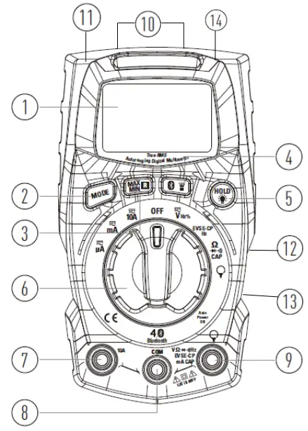
- LCD display
- MAX/MIN/Range button
- MODE Select button
- Rotary Function switch
- 10A input (RED)
- COM Input (-) BLACK for: See pkt 7
- + Input (RED) for V – Ω – Diode – continuity– capacitance –Hz% – Extern current clamp
- HOLD Data hold / backlight button
- Flashlight / Bluetooth button
- Fuse cover (backside down)
- Battery cover (backside upside)
- Holder for 2 testleads (backside)
- Flashlight (top)
- Slope stand (backside)
Display | Description | 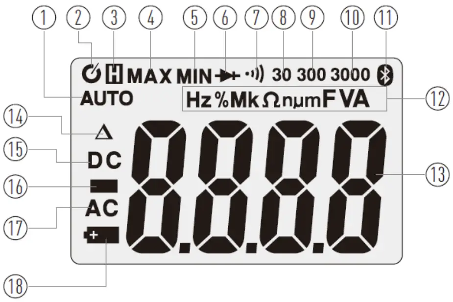 | |
| 1 | AUTO | Automatic range mode | |
| 2 |  | Auto Power Off | |
| 3 | Data Hold | ||
| 4-5 | MAX MIN | Maximum/minimum | |
| 6 | Diode test | ||
| 7 |
| Continuity test | |
| 8-9-10 | 30-300-3000 | Range | |
| 11 | Bluetooth for Elma Link APP | ||
| 12 | Hz % | Hertz, frequency / Hz percent (%) Duty Cycle | |
M, k, m, n, m | Unit of measure prefixes Mega – kilo – micro – nano – milli | ||
mV V | milli volt – Volt | ||
Ω | Ohm, Resistance | ||
A | Ampere, Current | ||
F | Farad, Capacitance | ||
| 13 | Measurement display digit | ||
| 14 |  | Relative value | |
| 15 | DC | DC Direct current / voltage | |
| 16 | Negative reading sign | ||
| 17 | AC | AC Alternating current / voltage | |
| 18 | Low battery indicator | ||

Operation
NOTES: Read and understand all Warning and Caution statements in this manual prior to using this meter. Set the function select switch to the OFF position when the meter is not in use.
Measurements
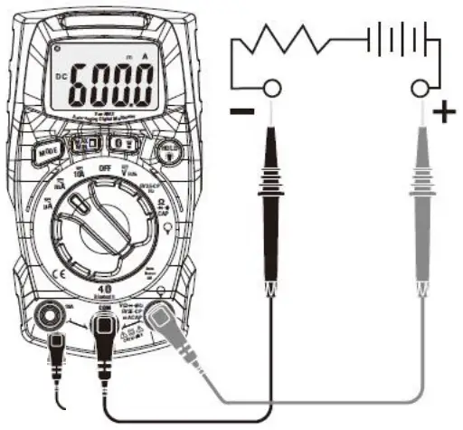
| 1. For AC DC Voltage – Frequency, Duty Cycle – EVSE-CP/ Hz – Resistance – Continuity – diode, and capacity measurement. Insert the red test lead to the red + ”VΩHz%.. terminal, and the black to the black – ”COM” terminal. Connect the test leads, with good contact, in parallel to the circuit under test. | |||||
| Measure settings | Measuring of | Func. switch | *Mode | Display | |
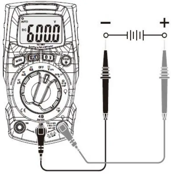 | 1a | DC- Voltage ± |  | 0 | DC V or m V |
| 1b | AC- Voltage |  | 0 | AC V | |
| Frequency | | 1 | Hz | ||
| Duty Cycle | | 2 | % | ||
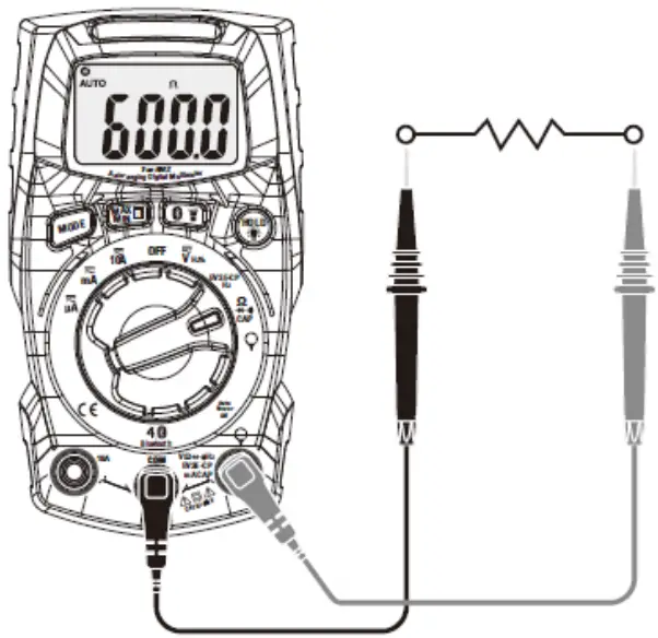 | Resistance | 0 | Ω or MΩ or KΩ | ||
| 1a. Notices the polarity when measuring DC., red to + and black to Com. | |||||
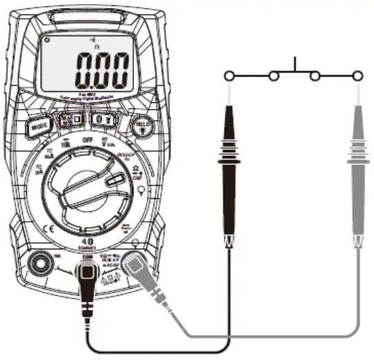 | 1c | Continuity | 1 | Ω and | |
| 1c. Notices for Continuity tests, if the resistance is < 50Ω, a tone will sound | |||||
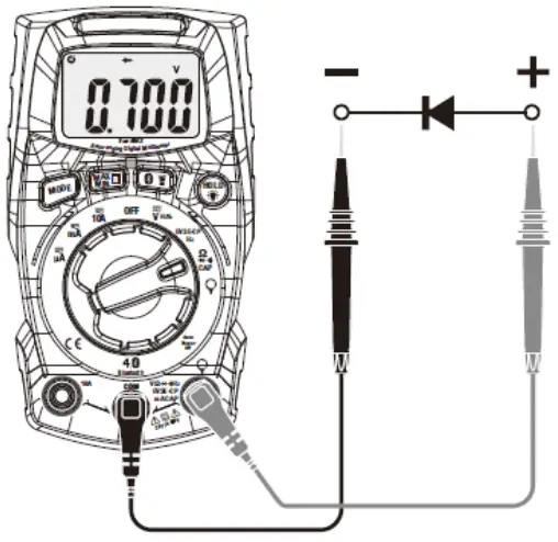 | 1d | Diode | 2 | and V | |
| 1d. Touch the test probes to the diode under test. Forward voltage will indicate 0.4V to 0.7V. Reverse polarity will indicate “OL”. The diode is OK Shorted diode will indicate near 0 mV and an open diode will indicate “OL” in both polarities. | |||||
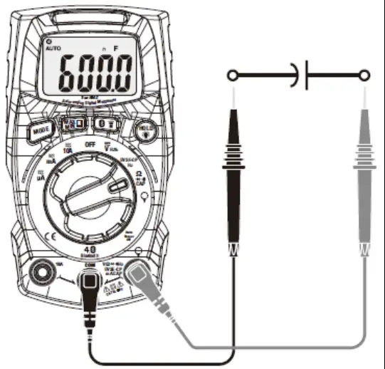 | 1e | Capacity | 3 | n F | |
| 1e. WARNING: To avoid electric shock, discharge the capacitor under test before measuring | |||||
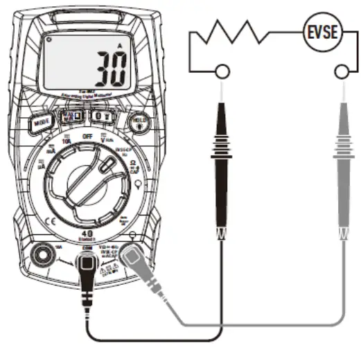 | 1f | EVSE-CP/Hz | EVSE-CP/Hz | 0 | A |
| 1 | Hz | ||||
| 1f. Read EVSE Current on the display – press Mode and read frequency | |||||
 2- 10A 3- mA/ µA | *2 | AC Current 10A |  | 0 | DC A |
| DC Current 10A | 1 | AC A | |||
| 3 | AC Current mA |  | 0 | DC mA | |
| DC Current mA | 1 | DC µA | |||
| AC Current µA |  | 0 | DC µA | ||
| DC Current µA | 1 | DC µA | |||
| 2-3 Connect the test leads, with good contact, in series to the circuit under test. *2 For current measurement max. 10 A (only for 30 sec. every 15 min.) | |||||
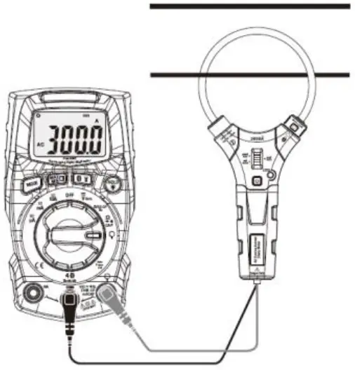 | 4 | ** Current with extern flex – clamp |  | 0 | A |
| ** Accessories Extern AC Clamp model ElmaFlex 430 EAN: 5706445840496 | |||||
| 4. Insert the red test lead from the external clamp to the red + ”VΩHz%.. terminal, and the black test lead to the black – ”COM” terminal. Open the clamp on the flexible ElmaFlex 430 with the turn knob, place the flex coil around a single phase and close the clamp completely again. Place the single phase in the middle of the flex coil for best results and read the current directly in the display. | |||||
Hold/ Back light
Hold Press the Hold/Backlight key, to “freeze” the measured value on the display, press the key again to cancel the freeze function. While Hold is active the display shows the symbol ![]() .
.
Backlight The LCD display is equipped with backlight for easier viewing in low-lighted areas. A long press at the Hold/Backlight key, will activate the backlight, a long press again will, turn off the backlight.
MAX/MIN RANGE
When performing measurements in normal AC / DC current and voltage functions, the MAX/MIN mode can be activated, which means that, in addition to the normal measurement results, you can also “save” the highest and lowest results, within the measurement period. Can’t be used for: External clamp, Resistance, Review, Diode, Capacity, Frequency, and Duty Cycle.
- The first short press at the MAX/MIN/RANGE button activates the MAX/MIN function. The icon “MAX” will appear. The meter will display and “freeze” the maximum reading value and will update only when a higher value occurs.
- Press again the MAX/MIN/RANGE button, the display icon “MIN” will appear. The meter will display and “freeze” the minimum reading value and will update only when a lower value occurs.
- To exit MAX/MIN mode press and hold the MAX/MIN/RANGE button for 1 seconds.
- Manuel range the first long press (1 sec.) at the MAX/MIN/RANGE key, will change the default, auto range measuring mode to manual range mode. AUTO disappears in the display. When entering the manual range mode, continue to press the button until the correct range is set.
Bluetooth/ Flash light
Flashlight. Short press the Bluetooth/ Flashlight button, will turn on or off the flashlight Bluetooth A long press at the Bluetooth/ Flashlight button will activate the Bluetooth data transmission function, thus allowing for the free Elma Link APP, as you can download at the App Store or Google play, for control of the instrument in a safe distance with your smart device, as well as save and transferring documentation or share measurements to the task you are doing. A long press again at the Bluetooth/ Flashlight button will turn off the Bluetooth function.
Automatic Power OFF (APO)
In order to conserve battery life, the meter will automatically turn off after approximately 15 minutes. To turn the meter on again press a random button or turn the function switch to the OFF position and then to the desired function position.
Turn off the Auto Power OFF function, press and hold the Mode button while turning on the instrument. The Mode button must be held down, until Elma 6100EVSE is fully started.
The Auto Power OFF symbol ![]() disappear from the display.
disappear from the display.
Maintenance
WARNING: To avoid electrical shock, disconnect the meter from any circuit, remove the test leads from the input terminals, and turn OFF the meter before opening the case for change of battery or fuses. Do not operate the meter with an open case.
Cleaning and Storage
Periodically wipe the case with a damp cloth and mild detergent; do not use abrasives or solvents. If the meter is stored away for 60 days or more, remove the battery and store it separately.
Battery replacement
- Remove the Phillips head screw that secures the rear battery cover (backside upside)
- Replace Two “AAA” 1.5V Alkaline Battery.
- Secure the battery cover.
Fuse replacement
The instrument is secured with 2 fuses for protection. When replacing, use the same type of fuses.
- Remove the Phillips head screw that secures the fuse cover (backside down)
- Replace the failed fuse. Type F10A/600V or Type F600mA/600V
- Secure the fuse cover
General specification
Recommended calibration interval: 1 year
| Display | 6000 counts LCD |
| Continuity check | Threshold 50W; Test current < 0.5mA |
| Diode test | Test current typical 0.3mA; Open circuit typical voltage < 3.3VDC |
| Low battery indication | |
| Over-range indication | ‘OL’ is displayed |
| Measurement rate | 2 readings per second, nominal |
| Input Impedance | 10MW (VDC and VAC) |
| AC response | True rms (50-400Hz, AAC – VAC and Fleksibel AC strømtang) |
| Operating Temperature | 5oC to 40oC |
| Storage Temperature | -20oC to 60oC |
| Operating Humidity | Max 80% up to 31oC decreasing linearly to 50% at 40oC |
| Storage Humidity | <80% |
| Operating Altitude | Max. 2000 meter |
| Battery | 2 Psc. ” AAA” 1.5V Alkaline battery |
| Fuses | 1 Type F10A/600V og 1. Type F600mA/600V |
| Auto power OFF | After approx. 15 min. |
| Dimensions & Weight | 121 x 67 x 35mm; 190g |
| Safety | For indoor use and in accordance with the requirements for double insulation to IEC1010-1 (2001): EN61010-1 (2001) Overvoltage Category III 600V ,Pollution Degree 2 |
Support
Elma Instruments A/S
Ryttermarken 2
DK-3520 Farum
T: +45 7022 1000
F: +45 7022 1001
[email protected]
www.elma.dk
Elma Instruments AS
Garver Ytteborgsvei
83 N-0977 Oslo
T +47 22 10 42 70
F +47 22 21 62 00
[email protected]
www.elma-instruments.no
Elma Instruments AB
Pepparvagen 27
S-123 56 Farsta
T: +46 (0)8-447 57 70
F: +46 (0)8-447 57 79
[email protected]
www.elma-instruments.se
![]()


