![]()
Model MM520
Operating Manual
True RMS Digital Multimeters
Overview
MN520 DMM is a small auto range, hand-held 3 1/2~3 5/6 bit true RMS multimeter featuring complete function, novel structure, high reliability and safety as well as large screen for display . It can be used for measuring AC/DC voltage and current, variable frequency voltage (V.F.C), resistance, diode, circuit on-off, capacitance, frequency ratio, NCV non-contact AC voltage sensing and so on, is an ideal portable maintenance instrument for users.
Accessory
Unpack and take out the instrument, please check following attachments carefully for completeness or intactness. In case of any shortage or damage, please contact with your supplier.
- An operating instruction manual
- Atest pen (CAT III 600V)10A
- Point-type K( nickel chromium~ nickel silicon) thermocouple
Safety Information
MN520 is designed in compliance with standards such as IEC/EN61010-1, pollution grade Il, overvoltage (CATITI600V) and double insulation standards. Please comply with operation instruction specified in the Manual; otherwise the protection provided by the instrument may be affected.
CE:This Meter complies with the standards EN 61010-1,EN 61010-2-030: in pollution degree 2, overvoltage category (CAT Ill 600V) and double insulation.
ETL/CETL: CONFORMS TO UL STD 61010-1, 61010-2-030
CERTIFIED TO CSA STD C22.2 No. 61010-1, 61010-2-030
- It is forbidden to use the product without having rear cap in place, or otherwise there will be electric shocking.
- Prior to use, inspect the insulation layer of test pen for intactness, confirming no breakage and broken line.
- When LCD display shows the icon “
 ”, it is required to replace the battery in time to ensure the measurement accuracy.
 - Range switch shall be set at the correct measurement position.
- In case of electric shock and damage to the instrument, signals being measured shall not exceed rated limit value.
- To prevent any damage to the instrument, it is forbidden to change the gear of range switch in measurement.
- After each measurement, disconnect table pen and the circuit being measured; after the current measurement, especially the measurement of large current, it is necessary to power off before disconnecting table pen and the circuit being measured.
- In case of electric shock, it is required to be cautious when voltage being measured higher than DC 60V or AC 30Vrms.
- Do not use the product in high-temperature or high-humidity environment, particularly in the damp environment in where the instrument performance may be severely degraded
- Refrain from changing the internal wiring in the clamp ammeter to guard against damage to the meter and danger.
- Clean the meter case with damp cloth and mild detergent rather than the abrasive material and solvent.
Electric Symbol
| Low electricity of internal battery | |
| Buzzing On-off | |
| Diode | |
| AC/DC | |
| Warning | |
| Battery to be measured | |
| Grounding | |
| Current clamp | |
| Double Insulation | |
| Comply with European Union directiv | |
| This symbol signify the product comply with both USA and Canada requirement |
Comprehensive Specification
- Maximum voltage between input terminal and grounding: see instruction about each input terminal protection voltage.
- 10A terminal (CE) is equipped with:
F 10A H 600V fast-acting fuse (06×25) mm - MA/UA terminal (CE) is equipped with:
MN520 -FF 0.6A H 600V fast-acting fuse (©6×32) mm - Maximum display: G000Refresh 2~3 times per second, display
“OL” in case of overrange .
Capacitance and frequency: 9999 count.
Duty ratio: 1~ 99.9%
Diode: 3.2V, displaying “OL” in case of overrange.
Range: auto/manual
Polarity: auto
Working temperature: 0°C ~40°C
Relative humidity: <75% when 0°C ~30°C, and <50% when 30°C ~40°C
Storage temperature: -10°C ~50°C - Electromagnetic compatibility:
In 1V/m radio frequency (RF) field: Overall accuracy=specified accuracy + 5% of range, and no specified index for RF over 1V/m. - Operating ASL: 0~2000m
- Internal battery: AA R6P 1.5Vx2
- Low electricity: LCD displays “”.
- Contour dimension: about (175x80x48.5) mm
- Weight: about 350g (inclusive of battery)
- Safety Standard: IEC/EN 61010-1: CATIIJ600V; Pollution grade II
- Accreditation: CE
Appearance Structure (See Figure 1)
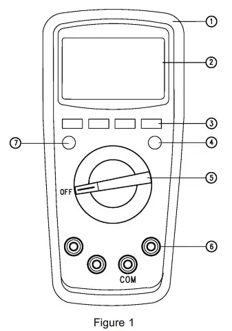
| 1. Case 2. LCD Display 3/4/7.: Selection buttons | 5. Range Switch 6. Measuring input terminal |
LCD Display (See Figure 2)
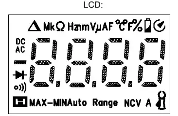
| Symbol | Instruction | |
| 1 | Data hold prompt | |
| 2 | Negative reading | |
| 3 | AC/DC | AC/DC measurement prompt |
| 4 | MAX-MIN | Maximum/Minimum/Maximum-Minimum value measurement prompt |
| 5 | Under-voltage internal battery | |
| 6 | Auto Range | Automatic range prompt |
| 7 | Diode measurement prompt | |
| 8 | Circuit on-off measurement prompt | |
| 9 | Relative measurement prompt | |
| 10 | Resistance units: Ohm, Kilohm and Megohm | |
| 11 | Hz/kHz/MHZ | requency units: Hz, kHz, MHz |
| 12 | % | Duty ratio measurement unit |
| 13 | mV/V | Voltage units: mV, V |
| 14 | pA/mA/A | Current units: pA, nnA, A |
| 15 | Capacitance units: nF, ii F, mF | |
| 16 | ºC | Centigrade temperature unit |
| 17 | °F | Fahrenheit temperature unit |
| 18 | (EF)NCV | Non-contact AC voltage sensing |
| 19 | Auto power-off prompt | |
| 20 | Current clamp |
Knobs and Keys for Range selection
| Range Location | Function |
| AC or DC voltage measurement | |
| Ω | Resistance measurement |
| Measurement of diode PN junction voltage | |
| Measurement of circuit on-off | |
| Capacitance measurement | |
| Hz | Frequency measurement |
| % | Duty ratio masurement |
| Temperature measurement | |
| AC/DC current measurement | |
| AC/DC current clamp measurement | |
| NCV | Non-contact AC voltage sensing |
| OFF | Switch off internal electric power |
Button:
RANGE button: it can be used for selecting auto/manual range. After pressing, it will switch one gear of switch, when reading the highest gear, jump to the lowest gear range and in turn. When the time of pressing button is =2s or switching a range, you’ll exit the manual range mode. (Only applicable for ![]() )
)
MAX/MIN button:
It can be used to automatically enter the manual range mode. In such case, auto shutdown function is disabled and maximum value is displayed, after another pressing on the button, the minimum value will be displayed and values are displayed in turn (maximum value-minimum value). When the time of pressing button is 22s or switching a range, you’ll exit data recording mode (only applicable for ![]() )
)
REL button:
It can be used to automatically enter the manual range mode. The current displayed value will be taken as the reference value and then the difference between the measured value and reference value will be displayed, after another press, you’ll exit the relative measurement mode. (Only applicable for ![]() ) The backlight will be illuminated when the time of pressing button is =2s, after about 15s, the backlight will be automatically turned off; the backlight will be turned off if pressing the key 22s when the backlight is illuminated, (Only applicable for UT139A full range: REL/LIGHT button)
) The backlight will be illuminated when the time of pressing button is =2s, after about 15s, the backlight will be automatically turned off; the backlight will be turned off if pressing the key 22s when the backlight is illuminated, (Only applicable for UT139A full range: REL/LIGHT button)
Hz/% button:
It can be used to select the mode Hz/%, only applicable for the selection of frequency, AC voltage/ current measurement modes.
SELECT button:
It can be used to select range (only applicable for multi-range). Under AC mode, press the button =2s, display “UFC”, enter V.F.C measurement mode and measure the variable frequency voltage. After another =2s pressing on the button, display “End” and exit the V.F.C measurement mode.
HOLD button: (Applicable for full range) It can be used to lock and hold the displayed value, in such case, LCD displays the prompt “[![]() ]’, after another press, it is unlocked and enter the normal measurement mode.
]’, after another press, it is unlocked and enter the normal measurement mode.
The backlight will be illuminated when the time of pressing button is 22s, after about 15s, the backlight will be automatically turned off; and the backlight will be turned off if pressing the key 22s when the backlight is illuminated.
Measurement Instruction
Check the built-in AA 1.5Vx2 battery, display will show the symbol “caa” when lack of power, and then replace battery in time. It is required to pay attention to the symbol “AA” beside the test pen socket, which reminds one of the fact that in case of measurement safety, testing voltage or current shall not exceed the specified value
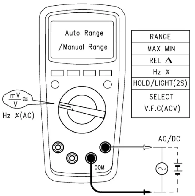
- AC and DC Voltage Measurement (See Figure 3)
- Connect the instrument with the load in parallel for measurement.
- When the input impedance of the instrument is about 10M 2 , the load may cause measurement error in the circuit with high impedance. In most cases, the error can be neglected (0.1% or lower) if the circuit impedance is under 10k /Manual Range
 Notes:
• It is forbidden to input voltage higher than 600Vrms, despite Cat! SELECT of the possibility of measuring higher voltage, as it may damage the instrument.
• It is required to avoid the electric shock in measuring high © AC/DC voltage.
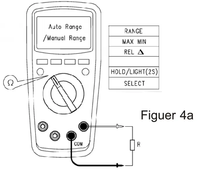
Resistance Measurement (See Figure 4a)
Connect the instrument with the load in parallel for measurement. Notes:
• The display will show “OL” when the measured resistance open-circuit or resistance value exceeds the maximum range of the instrument.
• Prior to measuring online resistance, it is necessary to switch off all powers in the circuits to be measured, and release all residual charges to ensure the measurement accuracy.
• IN measuring low resistance, a measurement error in resistance of about 0.1 2 ~0.2 2 will be resulted by the test pen. In order to acquire accurate reading, it is required to short circuit the test pen, take REL relative measurement mode to ensure the measurement accuracy.
• Check the test pen for any loosening or other reasons in case there is a resistance value no less than 0.50 when test pen is short circuited.
• Several seconds may be required for the reading stability wnen measuring high resistance, which is normal for high resistance measurement.
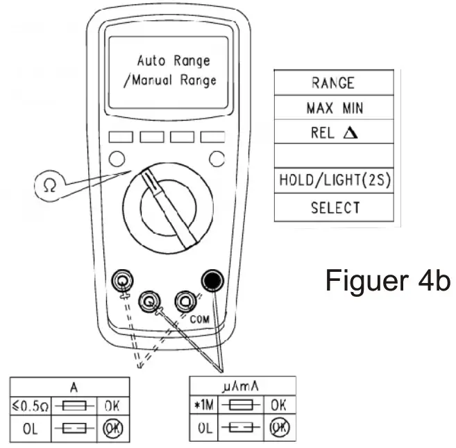
• By using the resistance measurement function, it is allowed to make self-checking of the built-in fuse, see (Figuer 4b).
• No input higher than DC 60V or AC 30V is allowed.
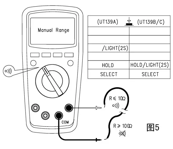
Circuit on-off measurement (See Figure 5)
If the resistance of two terminals to be measured is bigger than 1502, there will be a circuit break and buzzer will make no sound; if the resistance is <102, the circuit is deemed with good conductivity and buzzer will continuously sound. Notes
Notes
• Prior to measuring online circuit on-off, it is necessary to switch off all power supplies in the circuits to be measured and release all residual charges to ensure the measurement accuracy.
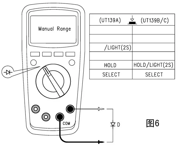
• To prevent personal injury, it is not allowed to input the voltage higher than DC 60V or AC 30V.Diode measurement (Figure 6)
“OL” will be displayed when the diode to be measured is an open circuit or polarity is reversely connected. For Silicon PN junction, the normal value is normally 500~800mvV. Notes
Notes
• Prior to measuring online diode, it is necessary to o switch off all power supplies in the circuits to be measured and release all residual charges to ensure the measurement accuracy.
• Test voltage for diode is about:
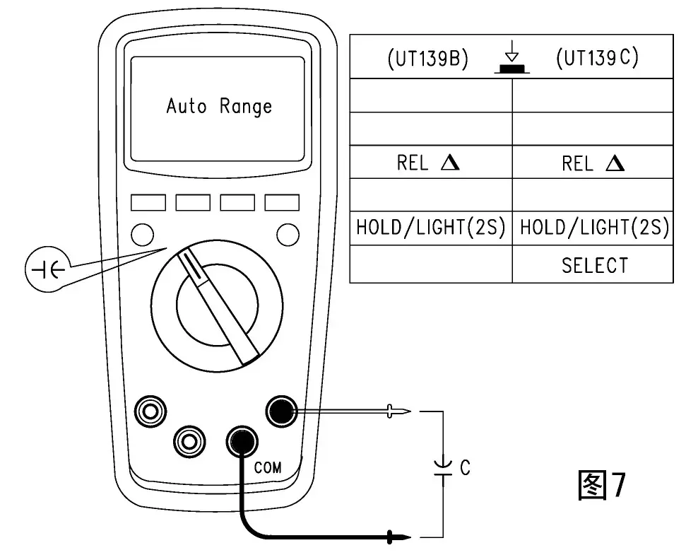
• To prevent personal injury, it is not allowed to input the voltage higher than DC 60V or AC 30VCapacitance measurement
(See Figure 7) The instrument, when without any input, will display a fixed reading which is the internal fixed capacitance value. When measuring small range gear capacitance, the above value shall be subtracted from the value to be measured to ensure the accuracy. The relative measurement REL function can be used to automatically subtract the value to facilitate the measurement. Notes
Notes
• The display will show “OL” when the capacitor to be becomes short-circuited or the capacitance value exceeds the maximum range of the instrument.
• Generally, several seconds will be taken to measure high-capacity capacitor.
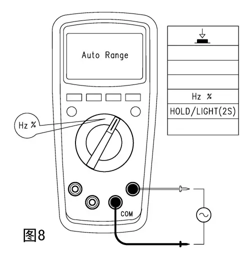
• To prevent damage to the instrument and personal injury, it is required before testing to release all residual charges, which is particularly important for capacitor with high voltage.Frequency/Duty Ratio Measurement
(See Figure 8) At the frequency measurement gear, press the button Hz/% to select frequency/duty ratio measurement mode. Notes
Notes
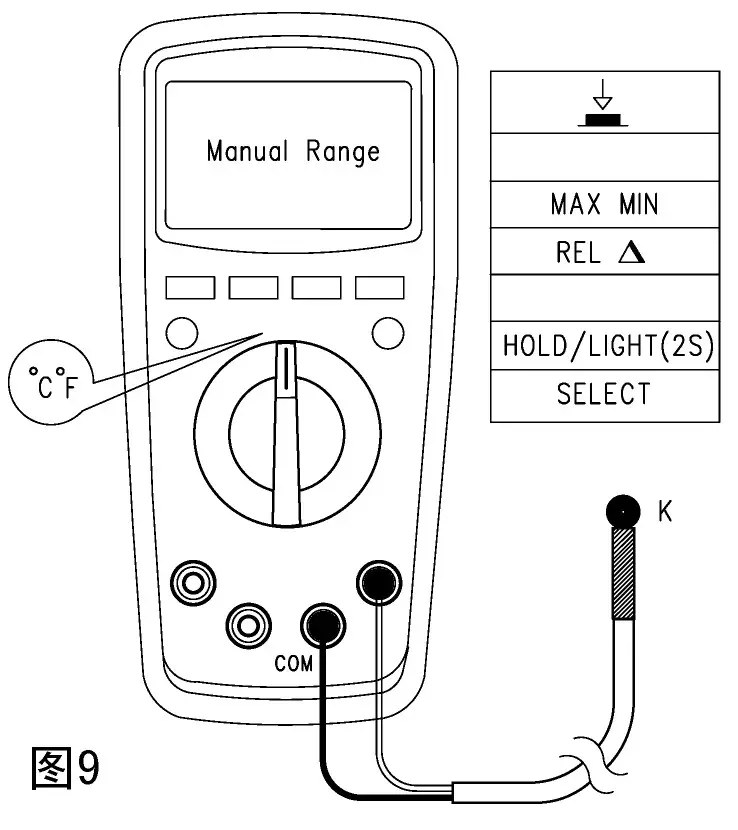
• To prevent personal injury, it is not allowed to input the voltage higher than DC 60V or AC 30VTemperature measurement
(See Figure 9) Temperature sensor: It is only applicable for K (Ni-Cr and Ni- Si) thermocouple. After startup, “OL” is displayed, complete Celsius or Fahrenheit temperature measurement by connecting the product with K-type temperature sensor.
“TF =1.8°C +32 Notes
Notes
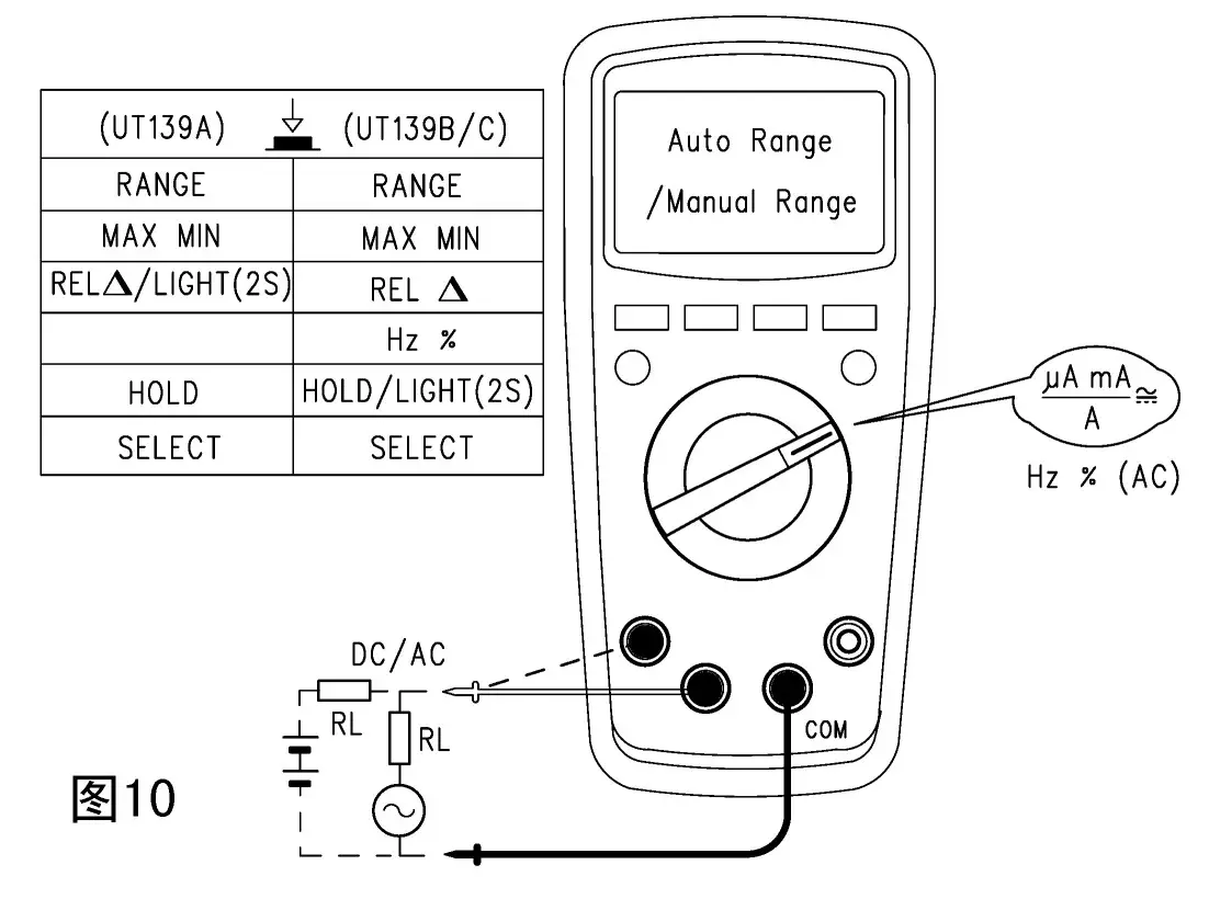
The point type K (Ni-Cr and Ni- Si) thermocouple is only applicable for the measurement of temperature under 230°C /446°T°.AC and DC current measurement (See Figure 10)
Connect the instrument with the load in serial for measurement.
AC measurement value will be true RMS. Notes
Notes
• Before connecting instrument in serial with the loop to be measured, switch off the power supply.
• IN measurement, it is required to use proper input terminal and function gear; if unable to estimate the current, the measurement should start with the high gear range.
• Fuses are provided inside the 10A, mA/ x linput jacks. It is forbidden to connect the table pen test pin in parallel with any circuit, especially the power supply terminal, which may cause damage to the instrument and personal injury. For security purposes, when measuring current higher than 5A, the time of each measurement should be controlled less than 10s and an interval of at least 15min should be maintained.
• When measuring AC current online, it is allowed to press the button Hz/% to display online AC frequency/ duty ratio.
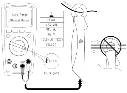
• GOA AC and DC current clamp measurement (See Figure 11).
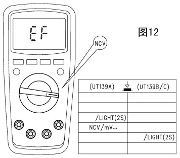
Connect as shown in the figure with the attached current clamp.- NCV Non-contact AC voltage sensing (See Figure 12)
If need to detect whether there is a AC voltage or electromagnetic field, allow the front end of the instrument be close to the object to be sensed. The analog quantity of sensed AC voltage is about: “EF” is displayed when <critical voltage. “—” ig displayed when MN520 >critical voltage, “- – – -” is designed according to the size of voltage Vd and accompanied by different buzzing sounds to mark the difference of sensed voltage. Notes
Notes
Test pen is not required for measurement when the range knob switch is set at “NCV”.
Other functions:
• After 2s of full display following startup, enter the normal measurement mode. “ErrE” will be displayed in case of any fault to the internal EEPROM.
• Auto power-off: the instrument will be “automatically powered off’ to save energy in case of no operation to the knob switch within 15min. Under auto power-off statuts, or any button of MN520 will “automatically arouse” the instrument, or restart the instrument by turning the knob switch to OFF. Under power-off status, press on SELECT and power on, the buzzer will make five sounds to remind that the auto power-off function has been cancelled. Restarting the instrument after power-off will recover the auto power-off function.
• Buzzer: A “Beep” sound (about 0.25s) from buzzer means the function button is valid when pressing any button or turning the function button. When measuring voltage or current: AC and DC voltage > about 600V mA gear AC/DC current 590mA When A gear AC/DC current is >10A, buzzer will make continuous sounds to remain the over-range. In addition, the buzzer make make 5 continuous sounds about 1min prior to auto power-off and then make one long sound prior to power-off. When the auto power-off function is cancelled, 5 sounds will be made by the buzzer every 15min.
• Low-voltage detection: it is used to detect the internal VDD. When the voltage is lower than 2.4V, the battery under-voltage symbol “’ will be displayed, and the normal operation is available; while when lower than 2.2V, no operation is allowed and only the symbol is displayed after startup.
• When the battery supply voltage is reduced to 2.6V, the LCD backlight is weak or can not start; measurement functions can still be used normally.
Technical Index
Accuracy: + (a% reading +b word number), one year of guarantee period. Ambient temperature: 23°C +5 (73.4° +91 ) Relative humidity: <75%.
- DC voltage measurement
Range Resolution Accuracy 60.00mV* 10pV ± (0.5%+2) 600.0mV** 0.1mV 6.000V 1mV ± (0.7%+3) 60.00V 10mV 600.0V 0.1V 600V 1V 10MΩ. (There will be unstable digital display in case of */** range open-circuit; after connecting with the load, it can be controlled s +1) Maximum input voltage: +600V
- AC voltage measurment
Range Accuracy Resolution 60.00mV ± (1.O%+3) 10pV 600.OmV 0.1mV 6.000V ± (0.8 %+3 ) 1mV 60.00V 10mV 600.0V 0.1V 600V ± (1.0%+3 ) 1V V.F.0 200.0V-600V 0.1/1V ± (4.0% +3) Input impedance: about 10MΩ.
Display the true RMS. Frequency response: 45~1kHz. (VFC: 45~400Hz)
Assurance of accuracy:5~ 100% range, an allowance of <10 words of residual reading for short-circuit.
It will be up to 3.0 when AC crest factor reaches full value (with except for 600V range, which is up to 1.5 when the range reaches the full value). Maximum input voltage: 600Vrms Resistance measurement
Range Accuracy Resolution 600.0Ω* ± (1.0 %+2) 0.1Ω 6.000kΩ ± (0.8%+2) 1Ω 60.00kΩ 10Ω 600.0kΩ 100Ω 6.000MΩ ± ( 1.2 %+3) 1kΩ 60.00MΩ ± (1.5%+5) 10k0Ω Range: measured value = displayed value — short-circuit value of test pen.
• Open-circuit: about *1V
• Overload protection: 600V-PTC- Circuit on-off, Pt diode measurement
Range Resolution Remark 
0.1Ω Circuit breakage resistance value is set as: >150Q, buzzer is soundless. Good conductivity is set as: .-_10Q buzzer sounds. 
1mv Open circuit voltage is about 3.2V
Normal voltage value of silicon PN junction is about 0.5-0.8V. - Capacitance Measurement
Range Resolution Accuracy 9.999nF 1μF Under REL status: ±(4%+10) 99.99nF-999.9pF 10μF-0.1pF ±(4%+5) 9.999mF-99.99mF 1μF-10pF ±10%(≤2mF) Overload protection: OUUV-F IU
For capacitor <1 uF, it is recommended to adopt REL measurement mode to ensure measurement accuracy. - Frequency/duty ratio measurement
Range Resolution Accuracy 9.999Hz-9.999MHz 0.001Hz-0.001MHz ± (0.1%+4) 1%-99.9% 0.1% Not defined Over-load protection: 600V-PTC
Input range a: (DC level is zero)
≤100kHz:100mMVrms≤a≤20Vrms
>100kKHzZz~1MHz : 200mVrms≤a≤20Vrms
>1MHz : 500mVrms≤a≤20Vrms
5MHz~10MHz : 900mVrms<a<20Vrms
Duty ratio %: only applicable for measurement <100kHz
Remark:
• During measurement of AC voltage or AC current, if need to read online frequency value or duty ratio, following input should be met: frequency response: <1kHz;
• AC voltage: mV range input 2100mV; V range input = range x6%
• AC current: input range a
4000/6000LA, 400/600mA, 10A range: a≥ range x6%
400/600,A, 40/60mA, 4/6A range: a≥ range x60% - Temperature measurement
Range Resolution Accuracy °C -40-1000°C -40-0°C 1°C ±3 >0-100°C ±(1.0%+3) >100-1000°C ±(2.0%+3) °F -40-1832°F -40-32°F 1°F ±5 >32—’212°F ± (1.5%+5) >212-1832°F ± (2.5%+5) Over-load protection: G00V-PTC
Remark: The point type K (Ni-Cr and Ni- Si) thermocouple is only applicable for the measurement of temperature under 230°C /446T - DC current measurement
Range Accuracy Resolution μA 600.0pA ± (0.7%+2) 0.1pA 6000pA 1pA mA 60.00mA 10pA 600.0mA 0.1mA A 6.000A ± (1.0%+3) 1mA 10.00A 10mA Over-load protection:
μ mA range:
F1 fuse: (p6x32)mm FFO.6A H 600V (CE)
F2 fuse: (p6x25)mm F 10A H 600V (CE) - AC current measurement
Range Resolution Accuracy Li A 600.0μ A 0.1μ A ±(1.0+3) 6000μ A 1μ A mA 60.00mA 10μ A 600.0mA 0.1mA A 6.000A 1 mA ±(1.2%+3) 10.00A 10mA Frequency response: 45~ 1kHz
Display: true RMS.
Assurance of accuracy: 5~ 100% range, an allowance of <2 words of residual reading for short-circuit.
It will be up to 3.0 when AC crest factor reaches full value. Over-load protection: (the same as the DC current over-load protection) - (60A) current clamp measurement
Range Resolution Accuracy 60A dc 0.01A ±(1.0+3) 60A ac ±(1.2+3) Over-load protection: 600V-PTC
Upkeep and Maintenance
![]() Warning: Power shall be switched off before opening the rear cover of the instrument; and the test pen shall be away from the input terminal and circuit to be measured.
Warning: Power shall be switched off before opening the rear cover of the instrument; and the test pen shall be away from the input terminal and circuit to be measured.
- Conventional upkeep and maintenance
* For upkeep and maintenance, wet cloth and mild cleanser rather than abrasive or solution shall be used to clean the meter housing.
* Please stop using and send for maintenance in case of any abnormal condition about the instrument.
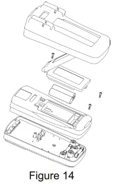
* The inspection or maintenance for instrument, if necessary, shall be performed by the qualified professional maintenance personnel or designated maintenance department. - Battery or fuse tube replacement (See Figure 14)
Built-in battery shall be replaced in time when LCD displays the under-voltage prompt “”, otherwise measurement accuracy may be affected. Battery specification: AA 1.5Vx2 (AS
Operating steps:
- Set the power switch at “Off’, take the test pen away from the Be input jack and remove the protective sleeve.
- Screw off one screw securing batter rear cover with screw driver, remove the cover and replace:
The under-voltage used battery and burnout fuse:
FFO.6A H 600V (CE) : - Screw off the second screw securing the rear cover with screw driver and remove the cover to replace the burnout F2 fuse (6×25) mm F 10AH 600V (CE).

Warranty Information
Triplett / Jewell Instruments extends the following warranty to the original purchaser of these goods for use. Triplett warrants to the original purchaser for use that the products sold by it will be free from defects in workmanship and material for a period of (1) one year from the date of purchase.
This warranty does not apply to any of our products which have been repaired or altered by unauthorized persons in any way or purchased from unauthorized distributors so as, in our sole judgment, to injure their stability or reliability, or which have been subject to misuse, abuse, misapplication, negligence, accident or which have had the serial numbers altered, defaced, or removed. Accessories, including batteries are not covered by this warranty.
Copyright © 2020 Triplett
www.triplett.com
The User Manual is subject to modification without further notice.


