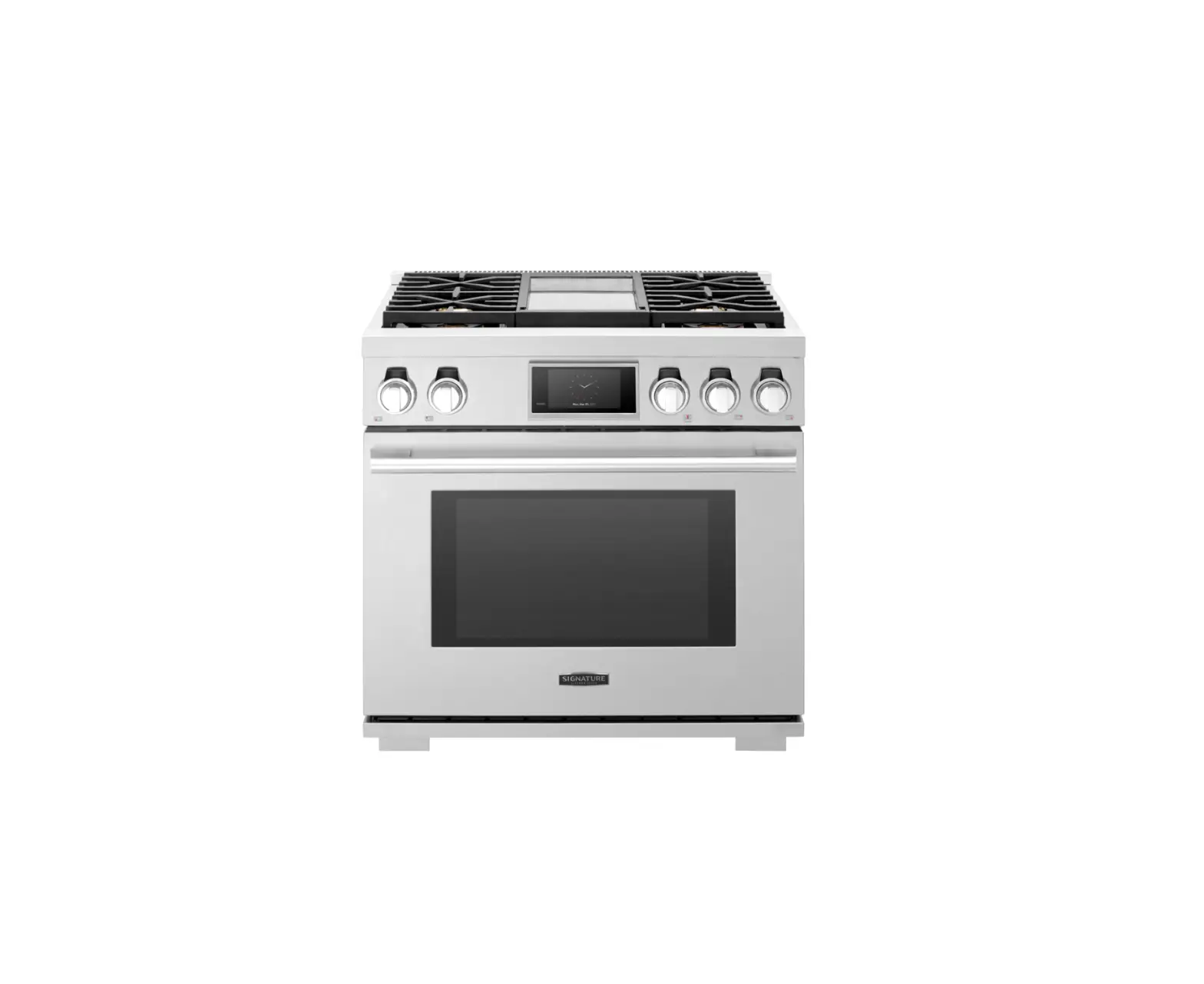
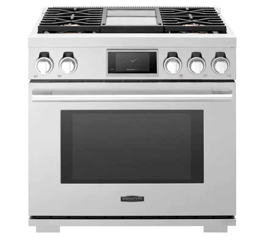
SIGNATURE KITCHEN SUITE SKSGR360GS 36 Inch Gas Pro Rangetop with 6 Burners
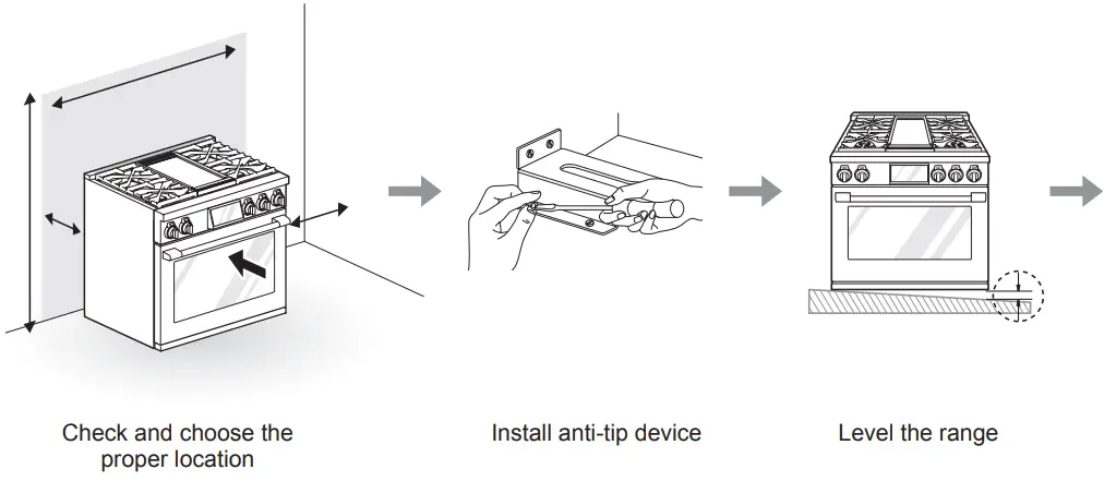
Installation Overview
Please read the following installation instructions first after purchasing this product or transporting it to another location.
Product Specifications
The appearance and specifications listed in this manual may vary due to constant product improvements.
| Oven Range Models | SKSGR360GS, SKSGR360S |
| Description | 36″ Gas Pro Range |
| Electrical requirements | SKSGR360GS : 0.98 kW 120 VAC SKSGR360S : 0.54 kW 120 VAC |
| Exterior dimensions | 35 7/8″ (W) x 35 1/4″ (H) x 26 3/4″ (D) (D with door closed) 91.1 cm (W) x 89.6 cm (H) x 67.9 cm (D) (D with door closed) |
| Height to cooking surface | 36″ (91.4 cm) |
| Net weight | SKSGR360GS : 396.8 lb (180 kg) SKSGR360S : 385.8 lb (175 kg) |
| Total capacity | 6.3 cu.ft. |
Before Installing the Range
| |
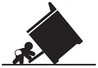 | Tip – Over Hazard A child or adult can tip the range and be killed. Verify the anti-tip bracket has been installed. Ensure the anti-tip bracket is engaged when the range is moved. Do not operate the range without the anti-tip bracket in place. Failure to follow these instructions can result in death or serious burns to children and adults. |
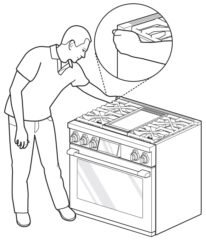
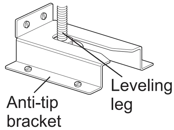 | To check that leveling leg is inserted into anti-tip bracket, grasp the top rear edge of the range and carefully attempt to tilt it forward. |
In the Commonwealth of Massachusetts
- This product must be installed by a licensed plumber or gas fitter.
- When using ball type gas shut-off valves, they must be the T-handle type.
- When using a flexible gas connector, it must not exceed 3 feet in length.
NOTE
|
Preparing for Installation
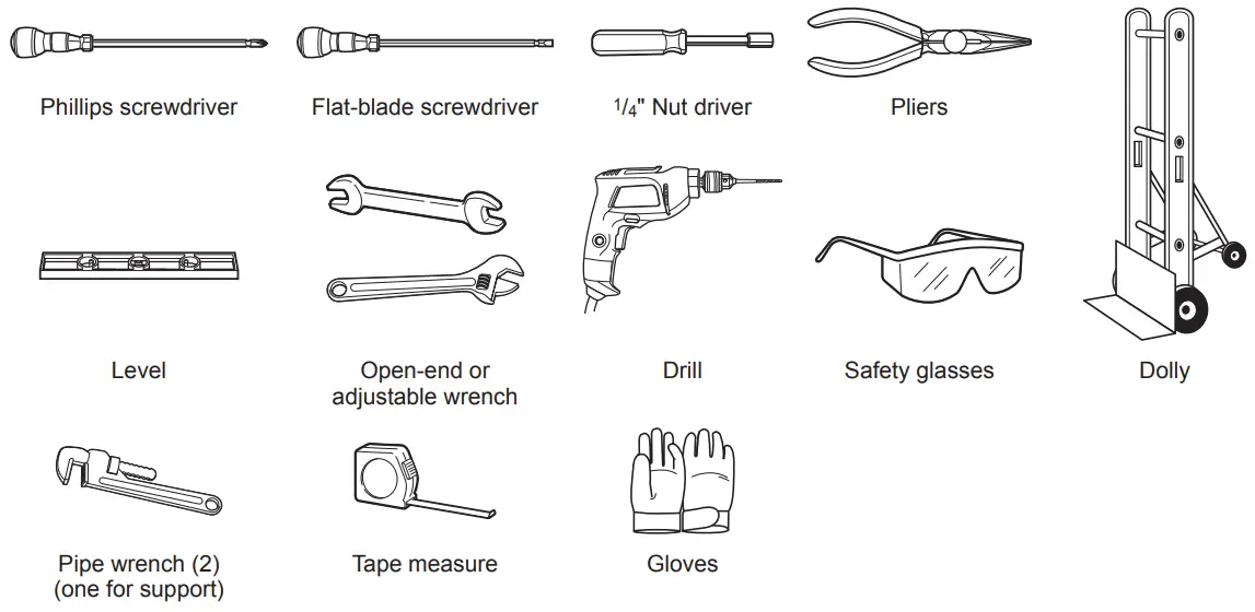
Tools Needed
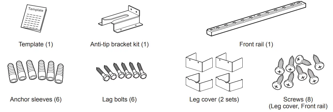
Parts Provided
Materials You May Need
- Gas line shut-off valve
- Pipe joint sealant that resists action of natural and LP gases
- Flexible metal appliance connector (3/4″ or 1/2″ NPT x 1/2″ I.D.)
Never use an old connector when installing a new range. - Flare union adapter for connection to gas supply line (3/4″ or 1/2″ NPT x 1/2″ I.D.)
- Flare union adapter for connection to pressure regulator on range (1/2″ NPT x 1/2″ I.D.)
- Liquid leak detector or soapy water
- Lag bolt or 1/2″ O.D. sleeve anchor (for concrete floors only)
Ventilation Requirement
It is recommended that these ranges be installed in conjunction with a suitable overhead vent hood.
- Install a hood with at least 600 CFM above a 30” or 36” range.
Due to the high heat capacity of this unit, particular attention should be paid to the hood and ductwork installation to assure it meets local building codes.
Do not install this product with an air curtain hood or other range hood that operates by blowing air down on the cooktop. This airflow may interfere with operation of the gas burners resulting in fire or explosion hazard. See below for the minimum clearance from the cooking surface to any horizontal surface above the range. Failure to observe this clearance may result in a fire hazard.
|
Proper Location
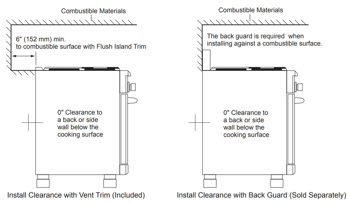
- The range is a free standing unit. If the unit is to be placed adjacent to cabinets, the clearances shown in “Install Clearance” are required. The same clearances apply to island installations, except for overhead cabinets, which must have a space wide enough to accept the flared island hood.
- The range should not be recessed into the cabinets beyond the edge of the front face of the oven. (see “Product Dimensions and Clearances”)
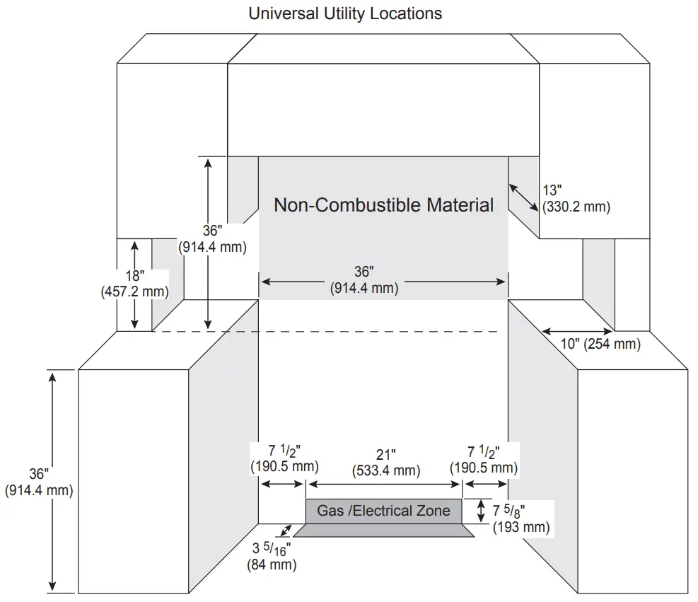
- The maximum depth of overhead cabinets installed on either side of the hood is 13”(330 mm).
Wall cabinets must be 18” (457 mm) above the countertop. - There is a 36” (914 mm) minimum clearance required between the top of the cooking surface and the bottom of an unprotected cabinet. A 30” (762 mm) clearance can be used when the bottom of the wood or metal cabinet is protected by not less than 1/4” (6 mm) of a flame retardant material covered with not less than No. 28 MSG sheet steel, 0.015” (0.38 mm) thick stainless steel, 0.024” (0.61 mm) aluminum, or 0.02” (0.51 mm) thick copper.
- Non-combustible surfaces are as defined in ‘National Fuel Gas Code'(ANSI Z223.1, Current Edition).
Clearances from non-combustible materials are not part of the ANSI Z21.1 scope and are not certified by CSA. Clearances of less than 36 inches (914.4 mm) must be approved by the local codes and/or by the local authority having jurisdiction.
|
When the floor covering ends at the front of the range, the area that the range will be installed on should be built up with plywood to the same level or higher than the floor covering. This will allow the range to be moved for cleaning and servicing, as well as provide proper air flow to the range.
Install Clearance
The location of gas burners and cooktop modules vary depending on the range model.
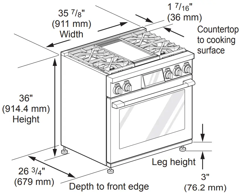
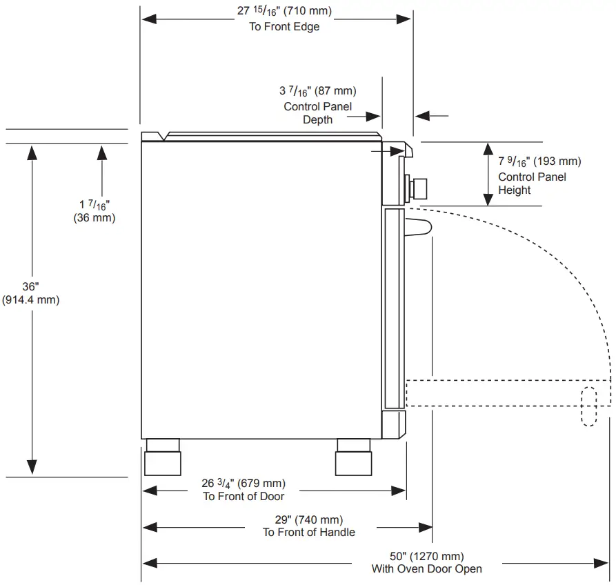
Product Dimensions and Clearances
Gas Supply
The range is designed to operate at a pressure of 5″ of water column on natural gas or 10″ of water column on LP.
Make sure you are supplying the range with the type of gas for which it is configured.
This range is convertible for use with natural or LP gas. When using this range with LP gas, conversion must be made by a qualified LP installer before attempting to operate the range.
For proper operation, the pressure of natural gas supplied to the regulator must be between 6″ and 10.5″ of water column.
For LP gas, the pressure supplied to the regulator must be between 11″ and 13″ of water column. When checking for correct operation of the regulator, the inlet pressure must be at least 1″ more than the operating (manifold) pressure as given above.
The pressure regulator located at the inlet of the range must remain in the supply line regardless of which type of gas is being used.
A flexible metal appliance connector used to connect the range to the gas supply line should have an I.D. of 5/8″ and a maximum length of 5 feet. In Canada, flexible connectors must be single wall metal connectors less than 6 feet in length.
Installing the Range
Unpacking the Range
|
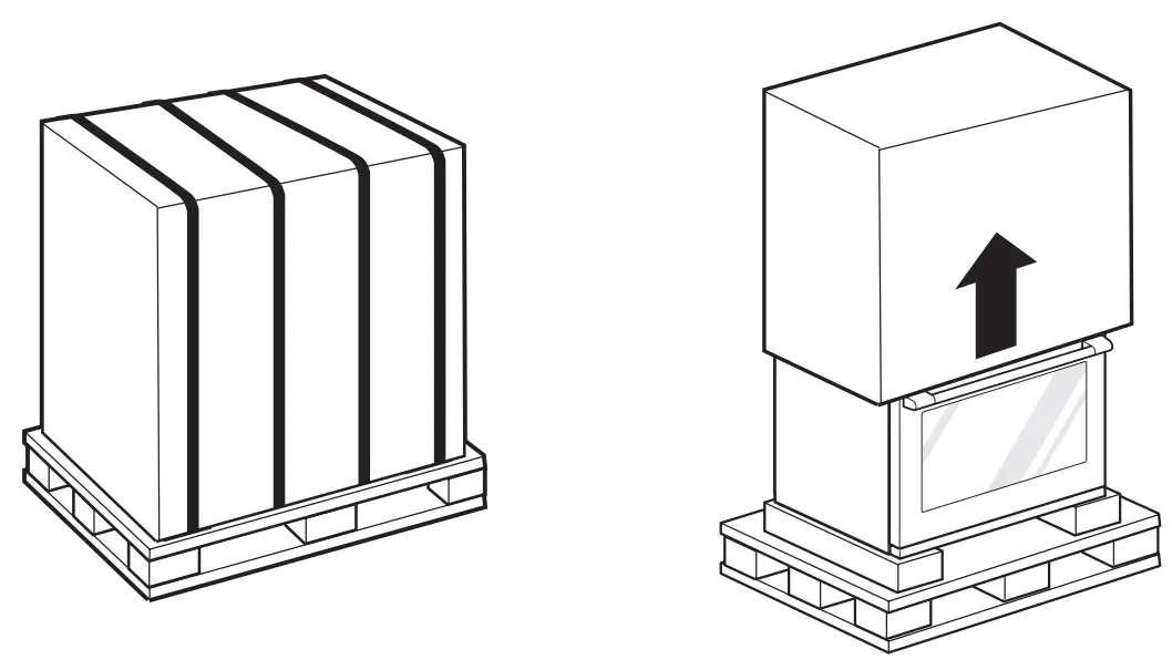
- Cut the packing straps. Lift the carton straight up. Remove packing material, tape and any temporary labels from your range before using but leave the adhesive-backed foam layer over the brushed-metal surface, to protect the finish from scratches. Do not remove any warning-type labels, the model and serial number label, or the Tech Sheet that is located on the back of the range.
- Remove the door(s). This will reduce the weight of the range during installation.
- The grates, burner heads, burner caps, trays and oven racks must be removed to facilitate handling. Do not remove the griddle element.
| NOTE Doors and passageways leading to the installation location require at least a 32″ (813 mm) opening. If the opening is less than 32″ (813 mm), the oven door(s) and control knobs must be removed. |
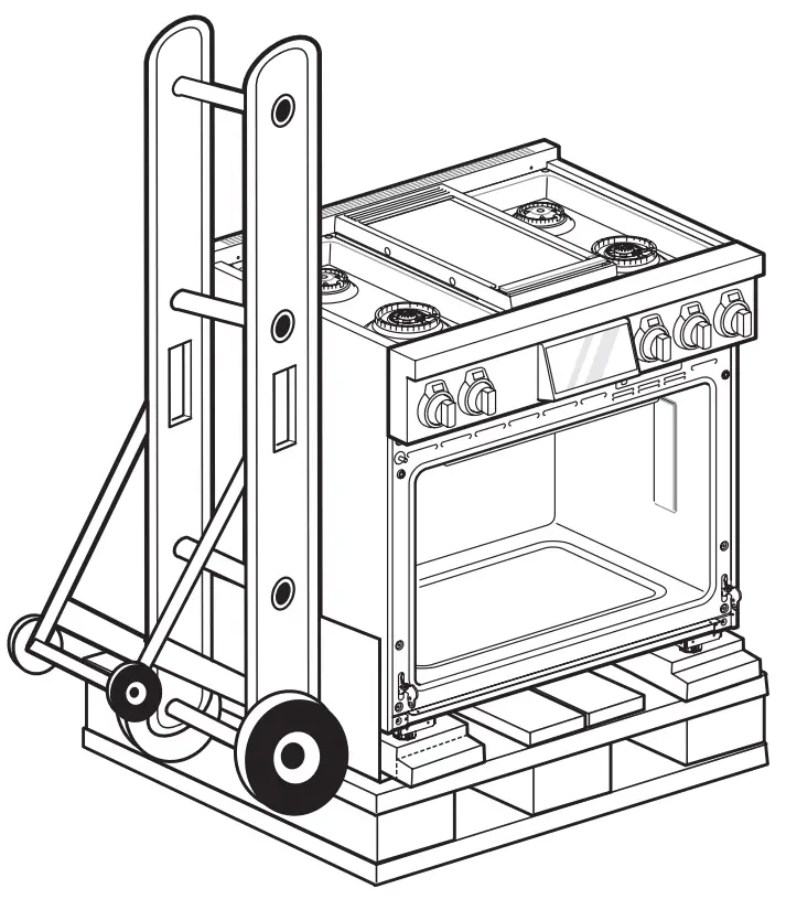
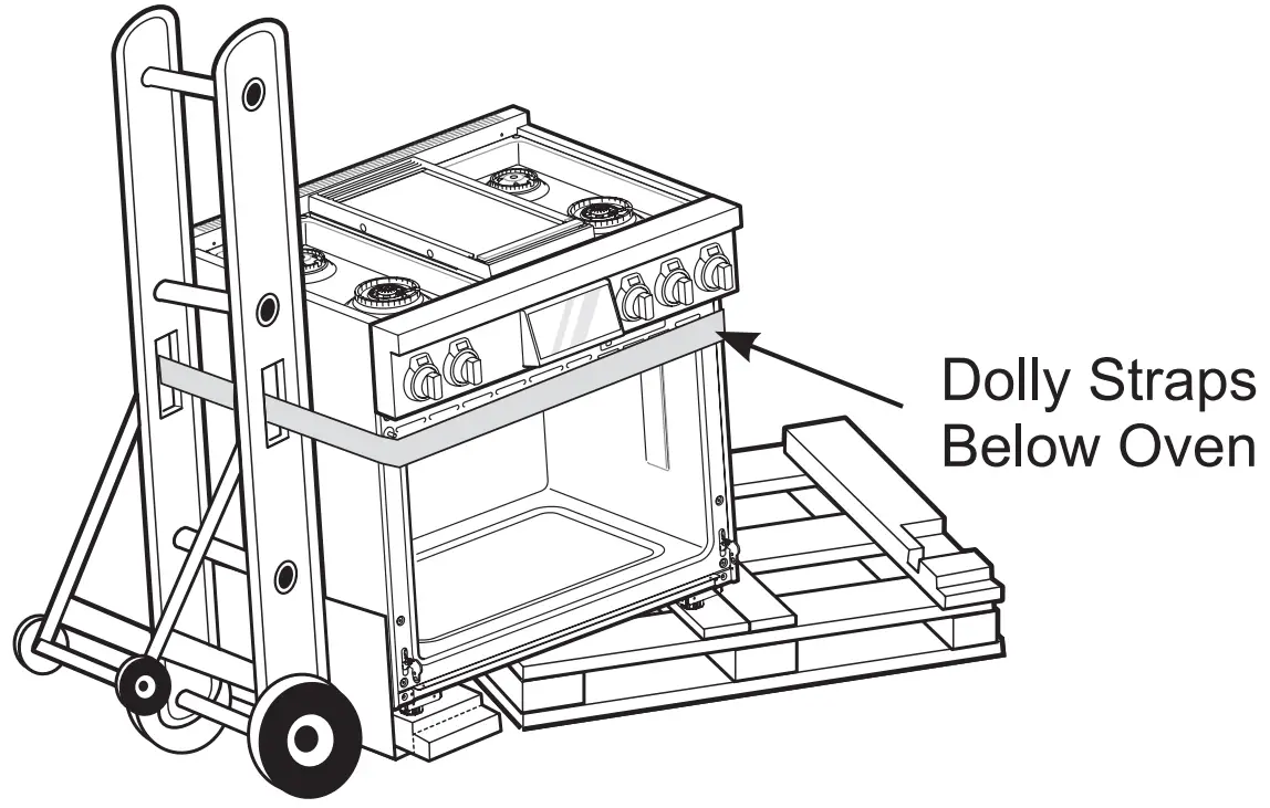
Moving the Range
|
- Remove the two screws on each bracket that secure the product to the pallet.

- Remove the oven door and racks.
NOTE - Instructions for removing the oven doors can be found on page 68.
- Carefully tilt the range from the side and insert a dolly under the range to remove the range from the pallet. Use additional help as required to remove the product from the pallet. To prevent damage to the sides of the range, it will be necessary to pad the corners beneath the straps on the dolly.


- Transport the range on the furniture dolly close to its final location, tip the range back to level, and carefully remove the dolly.
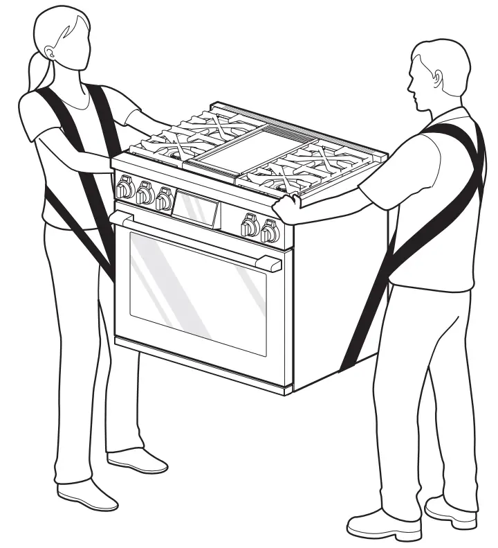
Your range is heavy and can be installed on soft floor coverings such as cushioned vinyl or carpeting.
Use care when moving the range on this type of flooring. Use a belt when moving the range to prevent damaging the floor. Or slide the range onto cardboard or plywood to avoid damaging the floor covering.
|
Installing the Anti-tip Device
| |
| Tip – Over Hazard A child or adult can tip the range and be killed. Verify the anti-tip bracket has been installed. Ensure the anti-tip bracket is engaged when the range is moved. Do not operate the range without the anti-tip bracket in place. Failure to follow these instructions can result in death or serious burns to children and adults. |
| To check that leveling leg is inserted into anti-tip bracket, grasp the top rear edge of the range and carefully attempt to tilt it forward. |
Locate the anti-tip bracket using the template.
An anti-tip bracket is packaged with the template.
The instructions include necessary information to complete the installation. Read and follow the range installation instruction sheet (template).
|
Leveling the Range
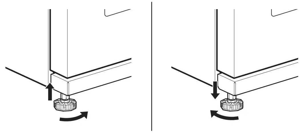
Front Legs
Level the range by adjusting the leveling legs with a wrench. Extending the legs slightly may also make it easier to insert the rear leg into the anti-tip bracket.
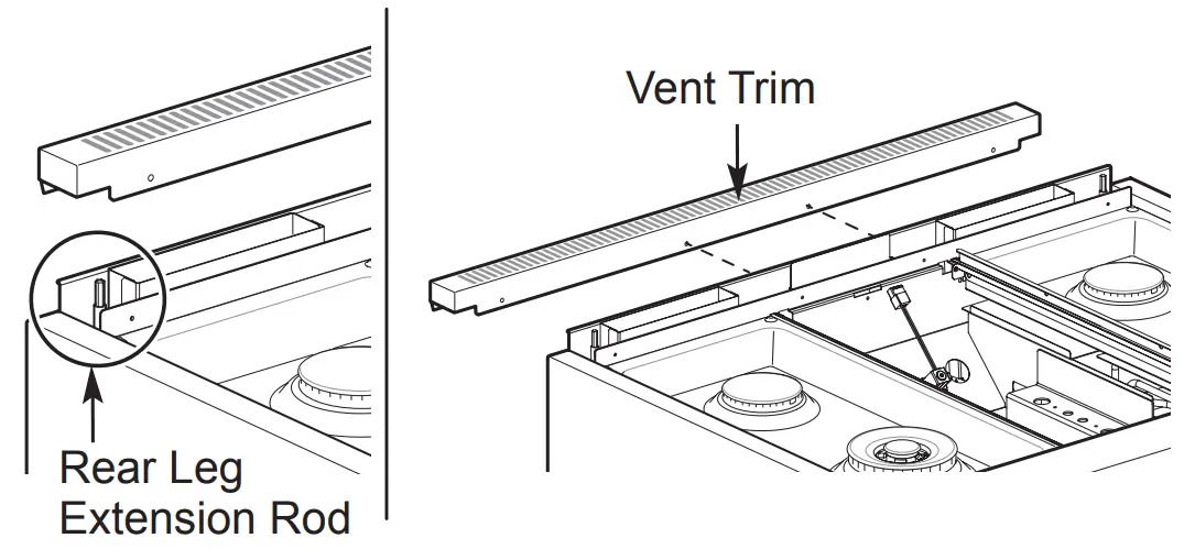
Rear Legs
To adjust the rear leveling legs, remove the 2 screws at the front of the vent trim and remove the trim.
Use an adjustable 7 mm box wrench to turn the rear leg extension rods at each corner.
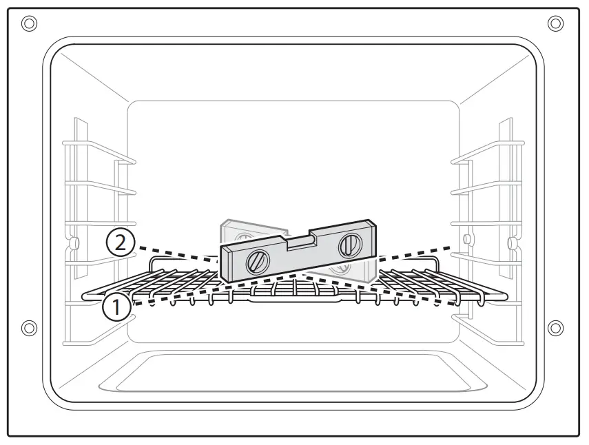
Use a level to check your adjustments. Place the level diagonally on the oven rack, and check each direction for level.
First check direction ①.
Then check direction ②. If the level doesn’t show level on the rack, adjust the leveling legs with a wrench.
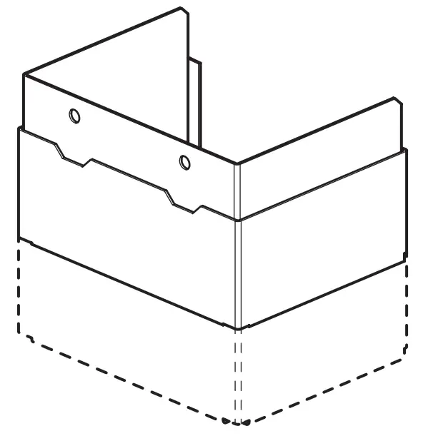
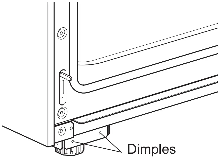
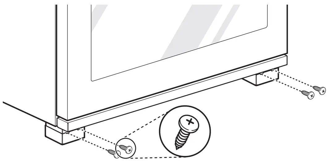
Installing the Leg Cover
- Remove the plastic covers from the stainless steel leg covers.
- Slide each small leg cover inside a larger leg cover. Cutouts should face up and both covers should be open at the back.

- Use the assembled covers to conceal the front leveling legs.
- Place the outer covers on the floor and slide the inner covers up until the holes at the top front snap over the dimples on the flanges on the bottom of the range.

- Insert the provided screws through the holes in the leg cover assemblies to secure them in place.

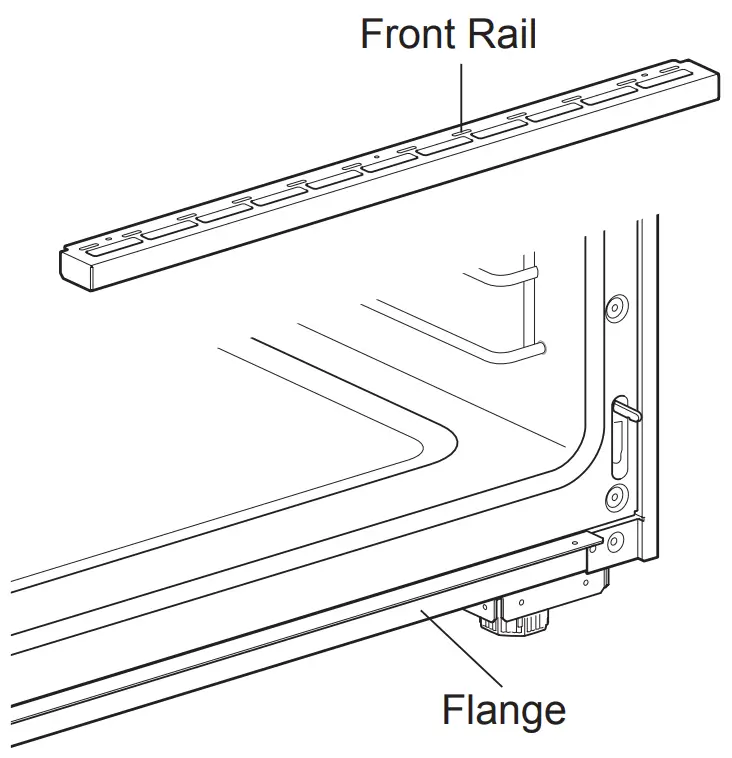
Installing Front Rail
- Remove the plastic film from the stainless steel front rail.
- Insert the front rail onto the flange below the oven door, aligning the holes in the top of the rail with the holes in the flange.

- Use the 3 screws provided to secure the front rail to the flange.
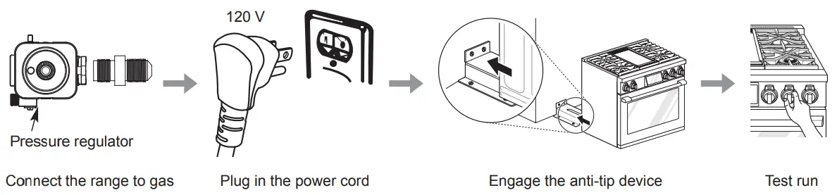
Connecting the Range to Gas
This appliance must be installed in accordance with local codes or, in the absence of local codes, with the National Fuel Gas Code, ANSI Z223.1/NFPA 54 or, in Canada, the Natural Gas and Propane Installation Code, CSA B149.1.
Shut off the range gas supply valve before removing the old range and leave it off until the new hook-up has been completed.
Because hard piping restricts movement of the range, a CSA International-certified flexible metal appliance connector should be used unless local codes require a hard-piped connection.
A manual valve must be installed in an accessible location in the gas piping external to the appliance for the purpose of turning on or shutting off gas to the appliance.
Never reuse an old connector when installing a new range.
To protect against gas leaks, use a qualified pipe joint sealant on all external threads.
- An inlet pipe is set on the left rear of this appliance. Hook up a gas hose that has 1/2″ NPT internal thread to the inlet pipe using a wrench.
- Apply sealing compound or Teflon tape at the connection.
- When all connections have been made, be sure all range controls are in the Off position and turn on the main gas supply valve. Gas leaks may occur in your system and create a hazard. Gas leaks may not be detected by smell alone.
Check all gas connection joints and fittings for leaks with a non-corrosive leak detection fluid, then wipe off.
Gas suppliers recommend you purchase and install a UL/CSA approved gas detector. Install and use in accordance with the installation instructions.
|
Flexible Connector Hookup
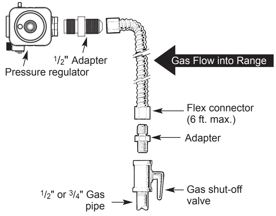
Pressure Regulator Position
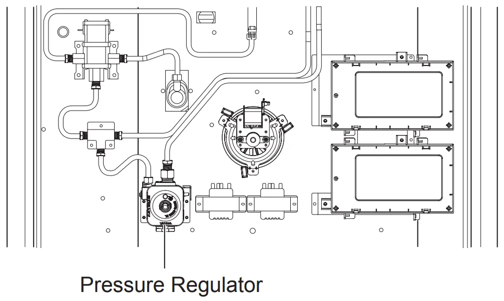
| NOTE Use a coin to unscrew the circular cap on the pressure regulator. |
Electrical Connections
Electrical Requirements
Connect to a 120 Volt, 60 Hz, properly grounded dedicated circuit protected by a 15 or 20 Amp circuit breaker, or slow blow fuse.
If an external electrical source is utilized, the appliance, when installed, must be electrically grounded in accordance with local codes or, in the absence of local codes, with the National Electrical Code, ANSI/NFPA 70 or the Canadian Electric Code, CSA C22.1-02.
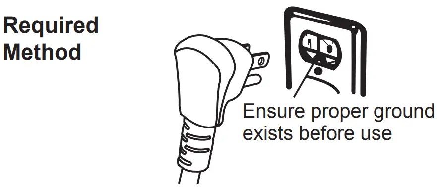
Grounding
IMPORTANT: FOR PERSONAL SAFETY, THIS APPLIANCE MUST BE PROPERLY GROUNDED.
The power cord of this appliance is equipped with a 3-prong (grounding) plug which mates with a standard 3-prong grounding wall receptacle to minimize the possibility of electric shock hazard from this appliance.
The customer should have the wall receptacle and circuit checked by a qualified electrician to make sure the receptacle is properly grounded.
Where a standard two-prong wall receptacle is encountered, it is the personal responsibility and obligation of the customer to have it replaced with a properly grounded three-prong wall receptacle.
DO NOT, UNDER ANY CIRCUMSTANCES, CUT OR REMOVE THE THIRD (GROUND) PRONG FROM THE POWER CORD.
A word about GFCI’s – GFCI’s are not required or recommended for gas range receptacles.
Ground Fault Circuit Interrupters (GFCI’s) are devices that sense leakage of current in a circuit and automatically switch off power when a threshold leakage level is detected. These devices must be manually reset by the consumer. The National Electrical Code requires the use of GFCI’s in kitchen receptacles installed to serve countertop surfaces.
Performance of the range will not be affected if operated on a GFCI-protected circuit but the occasional resetting of the circuit can become an annoyance.
Have the circuit checked by a qualified electrician to make sure the receptacle is properly grounded. |
Do not use an adapter plug. Disconnecting the power cord places undue strain on the adapter and leads to eventual failure of the adapter ground terminal.
Installation must conform with local codes or, in the absence of local codes, with the National Fuel Gas Code, ANSI Z223.1/NFPA 54 or, in Canada, the Natural Gas and Propane Installation Code, CSA B149.1.
The installation of appliances designed for mobile home installation must conform with the Manufactured Home Construction and Safety Standard, Title 24 CFR, Part 3280 (formerly the Federal Standard for Mobile Home Construction and Safety, Title 24, HUD, Part 280) or, when such standard is not applicable, the Standard for Manufactured Home Installations, latest edition (Manufactured Home Sites, Communities and Set-Ups), ANSI A225.1, latest edition, or with local codes. In Canada, mobile home installation must be in accordance with the current CAN/CSA Z240/MH Mobile Home Installation Code.
Sealing the Openings
Seal any openings in the wall and floor after electrical and gas supply connections are completed.
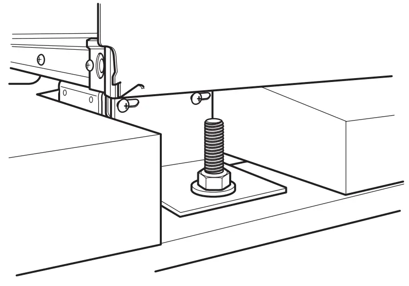
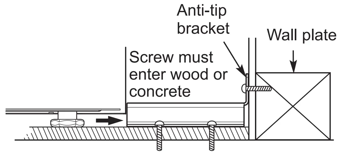
Engaging the Anti-tip Device
- Move the range close enough to the opening to plug into the receptacle.
- Slide the range into position ensuring that the back leg slides under the anti-tip bracket. The range should sit flush against the back wall when properly installed.
- Carefully attempt to tip the range forward to ensure that the anti-tip bracket is engaged properly. If properly installed, the anti-tip bracket will prevent the range from being tipped. If the range can be tipped, reinstall the range until the anti-tip bracket is properly installed and the range will not tip forward.
- Turn on electrical power. Check the range for proper operation.

Test Run
Check if the range is properly installed and run a test cycle.
- Remove all packing materials from inside the oven. Press Power button located next to the display and set initial settings such as language and time. (Refer to “Getting Started” in the Operation section.)
- Check the operation of the oven. Select Bake in the cooking mode screen then Start.
- The oven should finish preheating in 15 minutes.
- After making sure the oven operates properly, turn the temperature in the oven to 550 °F (288 °C) and leave the oven on for at least an hour. This helps remove any residual oil which might cause smoke or odor when first using the oven.
| NOTE Smoke may come out of the range when it is first used. |
Checking Ignition of the Surface Burners
Electric Ignition
Select a surface burner knob and simultaneously push in and turn to the Lite position. You will hear a clicking sound indicating proper operation of the spark module.
Once the air has been purged from the supply lines the burner should ignite within 4 seconds. After the burner ignites, rotate the knob out of the Lite position.
Try each burner in succession until all burners have been checked.
Quality of Flames
The combustion quality of the burner flames needs to be confirmed visually
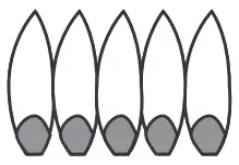 | A Yellow flames – Call for service. |
 | B Yellow tips on outer cones – This is normal for LP gas. |
 | C Soft blue flames – This is normal for natural gas. |
NOTE
|
Adjusting the Surface Burner to the Low Flame (Simmer) Setting
- The continuous simmer setting (Simmer or S4 position) needs to be adjusted on all burners.
- The Extra Low Simmer settings (S1 to S3 position) on the small burners are adjusted automatically as the flame cycles off and on.
- Remove the knob on the burner.
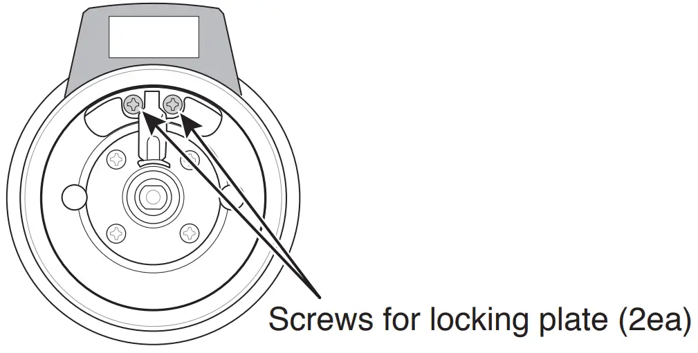
- Unscrew the 2 screws to remove the locking plate.

- Reassemble the burner knob.
- Light all surface burners.
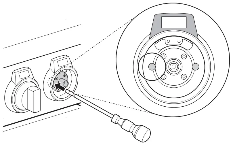
- Turn the knob on the burner being adjusted to the Simmer or S4 position then remove the knob.
- Insert a small, flat-blade screwdriver into the valve shaft and turn the adjustment screw until the flame reaches the desired size.

NOTE
Hold the valve shaft with one hand while turning the screw to adjust with the other. - Reassemble the locking plate and burner knob.
- Test the flame stability.
Test 1: Quickly turn the knob from the highest setting to the Simmer or S4 position. If the flame goes out, increase the flame size and test again.
Test 2: With the burner set to Simmer or S4, open and close the oven door quickly. If the air current extinguishes the flame, increase the flame height and test again. - Repeat steps 1-8 for each gas surface burner.