macnaught P58 Grease Pump Kit Owner’s Manual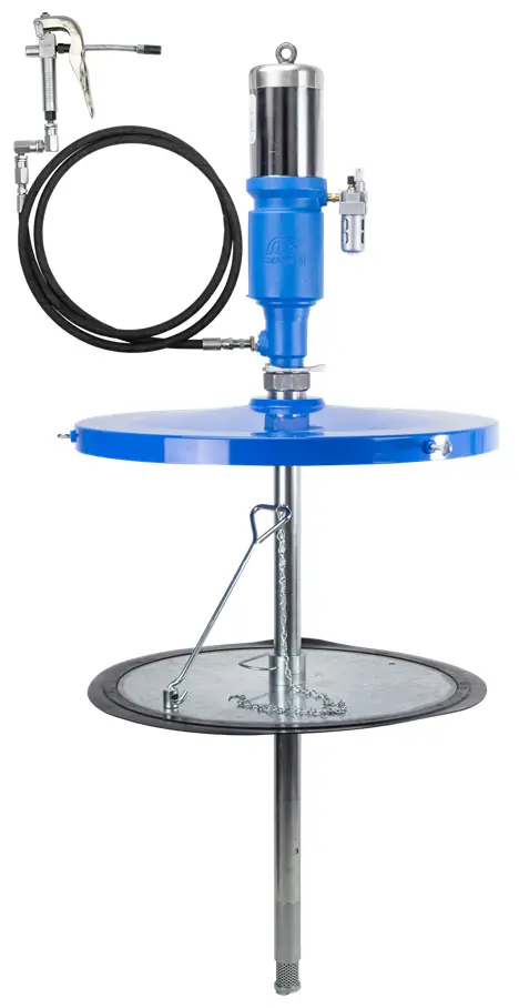
INTRODUCTION
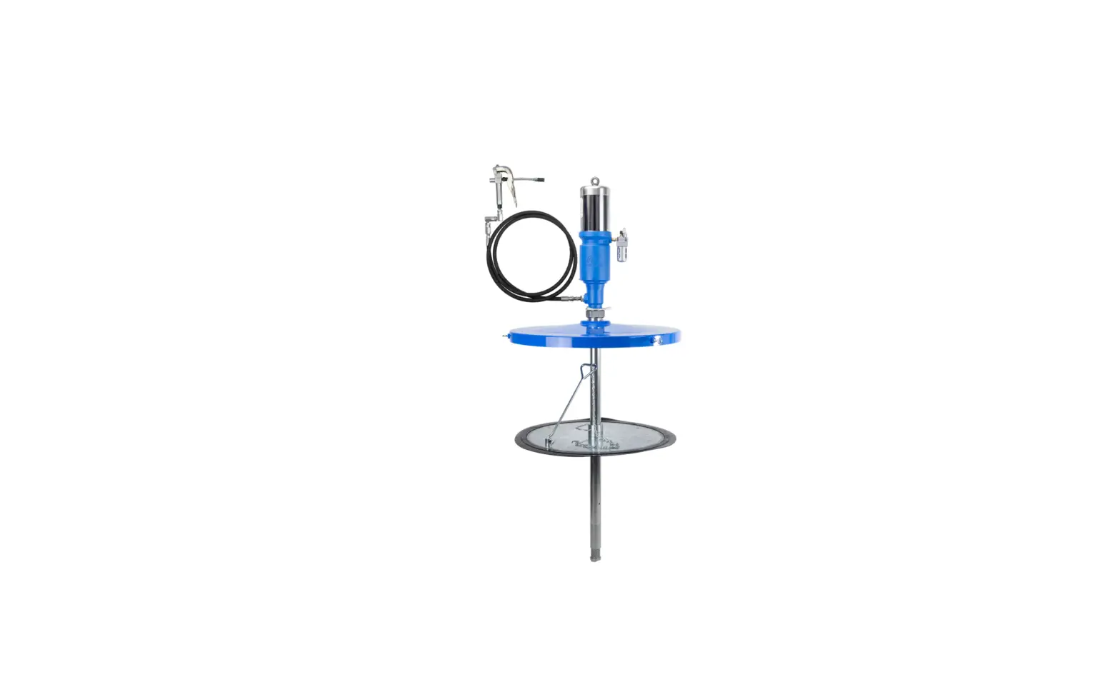
Thank you for purchasing the Macnaught P58 (58:1) air operated grease pump.
Macnaught has designed and manufactured this pump to the highest quality standards using premium quality materials and workmanship.
The P58 gerase pump has been designed for the transfer of grease over varying distances, through Macnaught retractable hose reels and Macnaught B2 Booser guns.
The P58 grease pump is suitable for use with greases up to and including NLGI No2 Viscosity.
There is an optional drum cover and follower plate kit available if required, which will fit the P58 to a steel 180kg (400lb) grease drum.
The follower plate features a rubber edge for effective drum wall wipe down, reducing waste and air pockets, plus a suction relief valve and long handle for easy removal from the bottom of empty grease drums.
PLEASE READ THIS SAFETY INFORMATION CAREFULLY BEFORE USE.
Read and retain this instruction manual to assist you in the operation of your new product.
- Make sure all operators have adequate access to the following instructions.


SAFETY INSTRUCTIONS
- Macnaught recommends the use of PPE equipment such as safety glasses, protective gloves, safety shoes etc before handling or using this product.
- Continual use of this product can potentially cause RSI injury (especially hand or arm injury)
- Do not modify or alter this product any way
- Use oil and fuel resistant thread tape or sealant on all threaded connections
- Never point the material outlet of the product at yourself or anyone else.
- The outllet nozzle should always be placed on the nozzle holder or in a safe secure location after use to prevent accidental operation.
- Only physically fit people should be authorised to use this product
- Ensure that any fluid spillage is cleaned up immediately to prevent slipping or injury.
- Only use this product in a safe environment, away from heat, fire or explosive atmospheres etc
- Keep hands are clear of any potential pinch points
- Ensure that the oil drum or container is always positioned on stable ground
- Only use genuine Macnaught replacement parts when repairing this product
- Heavy product – 2 people may be required for lifting product
Note: If the pump is connected to 690 kPa (100psi / 6.9 bar) air pressure this relates to a grease outlet pressure of 40,020kpa (5800psi / 400bar).
Do not exceed the maximum air inlet pressure of 1035kPa (150psi / 10.3bar). The pump requires a minimum air inlet pressure of 400kPa (60psi / 4bar).
DO NOT allow any part of the human body to come in front of, or in direct contact with the material outlet. Never point the nozzle of the control gun at yourself or anyone else.
Most accidents occur because of component rupture. Ensure that any and all components within the system will withstand the pressures being developed.
DO NOT exceed the pressure rating of any component installed in the system. If accidental injection should occur, seek immediate emergency medical attention.
DO NOT hit the unit if it fails to operate.
Refer to the ‘Trouble Shooting Guide’ or return the unit to the nearest Authorised Macnaught service centre.
Use suitable thread sealant (eg. Teflon tape) on all screwed fittings, but do not over tighten (to avoid damage).
NOTE: Before attempting any repairs or maintenance of this product, disconnect the air supply and release grease line pressure by operating hand piece / gun trigger.
Should more than one hose reel (grease outlet) be fitted to the system, the installation of high pressure on/off valves are recommended to isolate each reel (outlet) to facilitate maintenance.
![]() CAUTION
CAUTION
If pipework is required, it must be rated above the maximum working pressure of the pump. All the system components including hose reels, swivel joints and hand pieces must all be capable of with standing the high pressures generated by the pump.
The system is supplied complete with P58 pump, lid and follower plate. If you purchased the pump only you may also require the lid and follower kit.
INSTALLATION
![]() CAUTION
CAUTION
Make sure that all the components used in this grease system will withstand the high pressures being developed by the pump.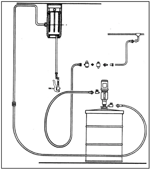
- Before connecting the air supply, the user should add a ‘stop’ compressed air valve to the air inlet on the pump. The air valve must be 1/4 turn type (allowing quick closure) and should be easily recognised.
- It is recommended that a micro fine (5 micron) air filter be fitted to ensure the maximum efficiency of the pump.
- Use thread tape on all threads and tighten firmley,
- The grease hose must be long enough to allow pump to be removed from drum without disconnecting it.
- Before use remove the air inlet plug, grease inlet cap and grease outlet plug from the pump stem.
- Position grease drum adjacent to air supply and grease line pipework.
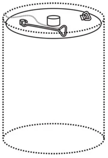
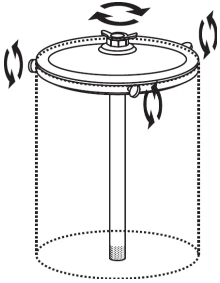
- Remove the lid from the grease drum.
- Insert follower plate squarely into drum
- Hook chain to top of drum

- Hook chain to top of drum
- Fit lid to drum
- Tighten thumb screws to secure lid
- Fit bung adapter to centre of the lid

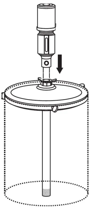
- Carefully slide pump through the lid and follower plate.
- Tighten bung adapter star nut to secure pump

- Tighten bung adapter star nut to secure pump
- Slowly open the air valve to prime grease through the pump.
- Turn off the air valve as soon as grease appears at the grease outlet on the pump.
- Connect the high pressure grease hose to the pump outlet.
Note:
The pump will stall when the system is full of grease. You will need to purge air in the system at initial start up
![]() CAUTION
CAUTION
Do not run pump dry.
Remember to switch off the air supply to the pump if the pump is not being used for extended periods (e.g. at the end of each day)
MAINTENANCE
![]() CAUTION
CAUTION
Before carrying out any maintenance disconnect the air supply and release grease pressure in the system
Inspect grease pump and associated hoses weekly for any signs of damage. Replace any suspect or damaged parts or components as required
Service Air Motor
(Can be carried out without removing pump from installation if required)
DISASSEMBLY
![]() CAUTION
CAUTION
- Disconnect the air supply and release grease line pressure before disassembly.
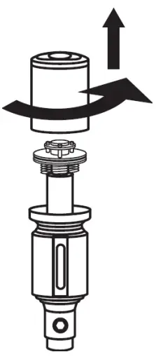
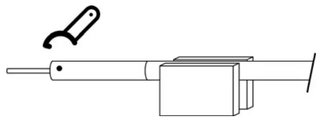
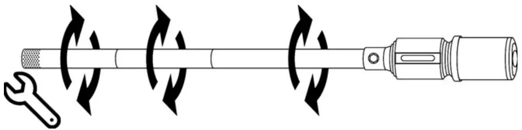
- Remove air cylinder assembly by using a strap spanner.

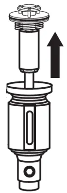
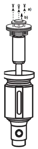
- Pull air piston up to allow easy access.

- a) Unscrew and remove 3 x screws and washers.
b) Remove air valve cap
- a) Place a rod through exhaust holes.
b) Hold rod and unscrew piston rod bolt.
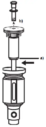
Note: Ensure you do not damage piston rod during disassembly.
ASSEMBLY
- Clean and inspect all parts. Replace any worn or damaged parts.
Note: Assembly is a reversal of the disassembly proceedure.
Use Loctite 222 (or similar retaining compound) on piston rod bolt thread and air valve cap screws.
Service Lower Pump
DISASSEMBLY
- Disconnect air supply and release grease line pressure.
- Remove grease hose from outlet.
- Withdraw pump from the grease drum (use a clean bench to carry out maintenance)
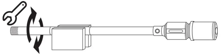
Note: Always use soft vice jaws (grips) to prevent against any chance of damaging pump tubes. - a. Hold connecting tube in a vice.
b. Unscrew and remove the strainer tube
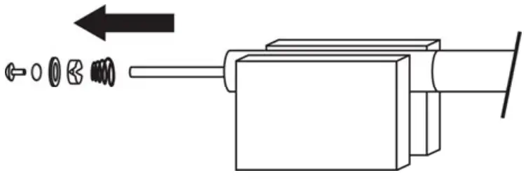
- Using the flats provided, carefully unscrew and remove primer, washer, plate seal, primer valve and spring.

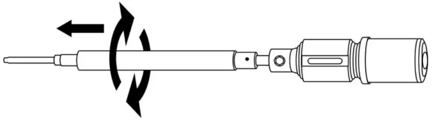
- Hold suction tube in vice, use a ‘C’ spanner to unscrew connecting tube.

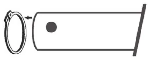
- Remove connecting tube, check circlip inside connecting tube for damage, replace if required.

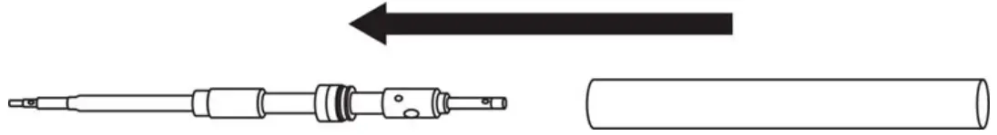
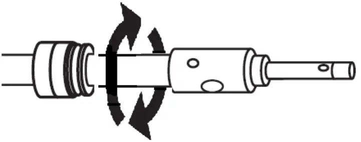
Note: Check for any burrs or damage on outside of connecting tube and repair with file or emery cloth. - a) Hold suction tube, place a suitable size rod into grease outlet and unscrew from pump body.
b) Pull suction tube down to expose piston rod/ connecting rod connection.
- a) Support piston rod, carefully remove spring pin
b) Unscrew and pull out rod assembly from bottom of the suction tube.
Note: Be carefull not to damage the thread on outlet fitting or rod assembly when unscrewing.
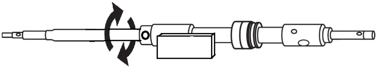
- a) Hold high pressure piston rod,
b) Place a rod through cross hole in primer rod, unscrew and remove primer rod, ball and spring.
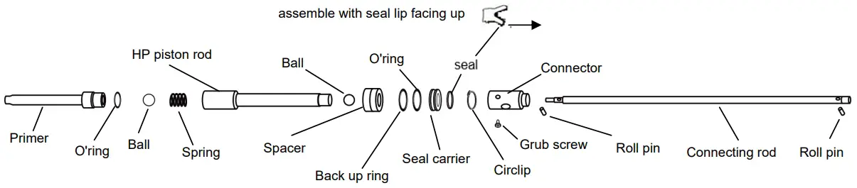
- Unscrew grub screw on connector and unscrew high pressure piston rod and remove ball.

- Remove seal assembly and spacer from high pressure piston (take note of correct seal orientation)

- Carefully remove piston rod from body.

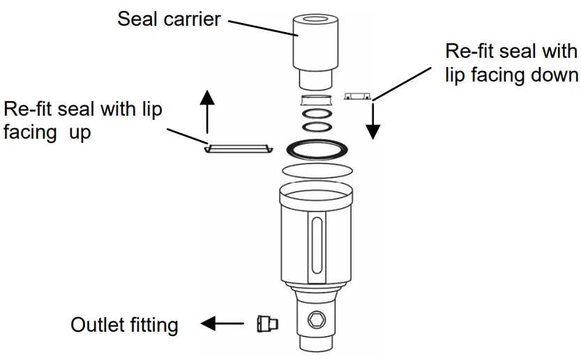
- a) Remove outlet fitting and seal carrier from housing.
b) Remove seals and o’rings from body and carrier.
- Clean and inspect all parts. Replace any worn or damaged parts before re-assembly.

ASSEMBLY
Note: Assembly is a reversal of the disassembly procedure.
Use Loctite 222 (or similar retaining compound) on piston rod bolt thread and air valve cap screws. Use Loctite 577 (or similar retaining compound) when fitting outlet fitting to seal carrier.
Note: Ensure correct orientation of all parts during assembly in particular the high pressure piston seal, seal and air seal. (Check parts diagram for correct orientation)
- During final assembly, use a spanner on strainer tube flats to tighten suction tube, connecting tube and strainer tubes all at the same time.

- Re-fit pump to the installation, fit the air regulator, oil lubricator and air fittings.
- Re-fit grease hose to the pump after priming the pump.
- Test pump for correct operation.
TROUBLESHOOTING GUIDE
Problem | Cause | Remedy |
| Air motor runs but does not pump grease | a) The grease is to thick or too cold | a) Use NLGI no 2 or thinner grease. (Store grease in a warm place) |
| b) The grease container is damaged causing the follower to stop (stick) | b) Repair or replace container. Follower must be able to move freely. | |
| Air motor runs slower than normal | Air pressure is too low | Increase air pressure. Minimum air pressure is 4000kPa/60psi/4bar. Maximum air pressure is 1035kPa/150psi/10.3bar |
| Air motor cycles intermittently when not using pump | a) Grease leaking from connections at hose, pipe or grease gun | a) Check all connections. Use thread sealant and tighten leaking connections. |
| b) High pressure seal is damaged | b) Replace high pressure seal | |
| Air leaks continuously from the air exhaust | a) Air piston seal is damaged | a) Replace air piston seal |
PARTS DIAGRAM
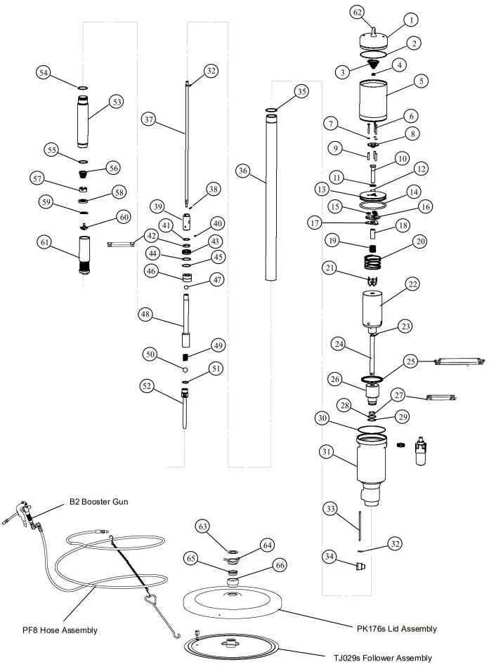
SPARE PARTS LIST
| ORDER FOR REPLACEMENT | |||||||
| Item | Part no | No off | Part or Set | Kit ref | Description | ||
| P58-1K P58-2K P58-3K | |||||||
| A | AIR MOTOR OVERHAUL KIT | ||||||
| B | LOWER PUMP SERVICE KIT | ||||||
| C | SEAL KIT | ||||||
| 1 | TJ022 | 1 | TG001s | AIR MOTOR CAP | |||
| 2 | BS045 | 1 | TE002s | A – C | O’RING | ||
| 3 | TE002 | 1 | C | BUFFER SPRING | |||
| 4 | TE003 | 1 | C | BUFFER STOPPER | |||
| 5 | TG002 | 1 | TG002s
TE011s
TJ012s (incl item 22) TJ004s (incl item 22) | HOUSING (AIR MOTOR) | |||
| 6 | N35 | 3 | A – C | SCREW (AIR VALVE) | |||
| 7 | N117 | 3 | A – C | WASHER | |||
| 8 | TE011 | 1 | A – C | AIR VALVE CAP | |||
| 9 | TG031 | 3 | A – C | SPACER (AIR VALVE) | |||
| 10 | TG003 | 1 | A | BOLT (PISTON ROD) | |||
| 11 | TG005 | 1 | A – C | WASHER | |||
| 12 | BS016 | 1 | A – C | O’RING | |||
| 13 | TG004 | 1 | A | PISTON | |||
| 14 | BS343 | 1 | A – C | O’RING | |||
| 15 | TG011 | 3 | A – C | RUBBER BUSH | |||
| 16 | TG032 | 1 | A – C | WASHER | |||
| 17 | TG030 | 1 | A | SEAL PLATE | |||
| 18 | TG036 | 1 | A | SPACER | |||
| 19 | TC38 | 1 | A | SPRING (AIR VALVE) | |||
| 20 | TG007 | 1 | A | SPRING (PISTON) | |||
| 21 | TJ008 | 1 | A | RETAINER | |||
| 22 | TJ012 | 1 | PISTON ROD (LARGE) | ||||
| 23 | N245 | 1 | C | SEL LOK PIN (3 X 30) | |||
| 24 | TJ004 | 1 | PISTON ROD (SMALL) | ||||
| 25 | TJ003 | 1 | A – C | SEAL (AIR) | |||
| 26 | TJ010 | 1 | TJ010s | SEAL CARRIER | |||
| 27 | TL005 | 1 | B – C | SEAL | |||
| 28 | TJ038 | 1 | B – C | BACK UP RING | |||
| 29 | BS024 | 1 | B – C | O’RING | |||
| 30 | BS046 | 1 | TJ001s (incl item 31,32) TE020s TJ021s
TJ009s (incl item 34) TJ016s (incl item 37) | C | O’RING | ||
| 31 | TJ001 | 1 | BODY | ||||
| 32 | N350 | 2 | B – C | PIN (SPRING) | |||
| 33 | TE020 | 1 | SILENCER | ||||
| 34 | TJ021 | 1 | OUTLET FITTING | ||||
| 35 | N254 | 1 | B – C | CIRCLIP | |||
| 36 | TJ009 | 1 | SUCTION TUBE (180KG) | ||||
| 37 | TJ016 | 1 | CONNECTING ROD (180KG) | ||||
| 38 | N349 | 1 | B – C | PIN (SPRING) | |||
| 39 | TJ002 | 1 | TJ002s | CONNECTOR (PISTON ROD) | |||
| 40 | N579 | 1 | B – C | GRUB SCREW | |||
| 41 | N422 | 1 | B – C | CIRCLIP | |||
| 42 | TJ005 | 1 | TJ005s | B – C | HIGH PRESSURE SEAL | ||
| 43 | TJ007 | 1 | B | SEAL CARRIER | |||
| 44 | TJ037 | 1 | B – C | BACK UP RING | |||
| 45 | BS025 | 1 | B – C | O’RING | |||
| 46 | TJ019 | 1 | B | SPACER HP | |||
| 47 | N412 | 1 | TJ035s
TJ034s TJ018s (incl item 50) | B | BALL | ||
| 48 | TJ035 | 1 | PISTON ROD (HIGH PRESSURE) | ||||
| 49 | TJ020 | 1 | B – C | SPRING | |||
| 50 | N416 | 1 | B – C | STEEL BALL | |||
| 51 | BS019 | B – C | O’RING | ||||
| 52 | TJ034 | 1 | B – C | PRIMER ROD | |||
| 53 | TJ018 | 1 | CONNECTING TUBE | ||||
| 54 | BS028 | 1 |
TJ014s | B | O’RING | ||
| 55 | N1300-0143APP | B | CIRCLIP | ||||
| 56 | TJ060 | 1 | B | SPRING | |||
| 57 | TJ015 | 1 | B | VALVE SEAT | |||
| 58 | TJ014 | 1 | B | PLATE SEAL | |||
| 59 | TJ043 | 1 | B | WASHER (PRIMER) | |||
| 60 | TJ042 | 1 | B | PRIMER | |||
| 61 | TJ013 | 1 | TJ013s TJ044s | STRAINER TUBE (BOTTOM) | |||
| 62 | TJ044 | EYE BOLT | |||||
| 63 | TJ031 | 1 | TJ023s | B – C | WEATHER SEAL | ||
| 64 | TE026 | 1 | BUNG NUT (STAR) | ||||
| 65 | TJ023 | 1 | CLAMP RING | ||||
| 66 | TE024 | 1 | BUNG NUT (BOTTOM) | ||||
SPECIFICATIONS
P58 (58:1) SPECIFICATIONS
| Pump Ratio | 58:01:00 |
| Maximum Air Pressure | 1035kPa / 150psi / 10.3Bar |
| Munimum Air Pressure | 400kPa / 60psi / 4Bar |
| Air consumption | 23.5 scfm@ 120psi, 20 deg C |
| Output (At the pump) | 6kg/min (free flow) @ 120psi, 20 deg C |
| Air Inlet Thread | 1/4″NPT |
| Pump Outlet Thread | 3/8″BSP (3/8″NPT USA) |
| Bung Adapter Thread | 2″M |
Support
Note:
This product should be disposed of according to all applicable local and national government environment regulations and guidelines.
For Warranty Terms and Conditions see macnaught.com.au
Head Office – Australia Macnaught Pty Limited
ABN 66 000 075 785
41-49 Henderson St Turella,
NSW, 2005 Sydney, Australia.
T: +61 2 9567 0401
F: +61 2 9597 7773
W: www.macnaught.com.au
Macnaught USA Inc (North & South America)
614 South Ware Blvd. Tampa, Florida, 33619 United States.
T: +1813 628 5506 F: +1813 628 5506
E: [email protected]
W: www.macnaughtusa.com