POWER SOLID PSi400VA#12VPVT Inverter 400VA
Product Information
The product is a PSi400VA#12VPVT inverter that can convert DC power from a battery or solar panel into AC power for household or commercial use. It has an input capacity of 400VA/250W and a nominal DC voltage of 12V. The inverter can automatically sense the input voltage range and frequency of 154-265VAC and 50-60Hz. The output power is 250W with a pure sinewave frequency of 50/60Hz and a transfer time of 50%. The inverter has LED indicators that show the power source and charging status. It also has function keys for setting and configuration.
Product Usage Instructions
- Function Setting
To enter setting mode, press the ENTER button for 10 seconds. To exit setting mode, press the ESC button repeatedly. Use the UP or DOWN button to choose the parameter and then press ENTER to select it. When the parameter is flashing, use UP or DOWN to change it and then press ENTER to confirm. The setting icon will flash when setting, the left-sided frame of the parameter will flash when the setting succeeds, and the ERROR light will turn on when the setting fails. - Care and Maintenance
Refer to the user manual for instructions on the care and maintenance of the product. - Rapid Troubleshooting and Maintenance
Refer to the user manual for instructions on rapid troubleshooting and maintenance of the product. - Technical Datasheet
The technical datasheet provides information on the product specifications, including input and output capacity, voltage range and frequency, waveform, transfer time, low voltage shutdown and recovery, high voltage alarm and recovery, and optional PV array power. The datasheet also provides information on the product’s environmental conditions, including temperature, humidity, and acoustic noise. - Appendix
The appendix provides information on how to choose and configure PV panels for use with the inverter. It lists the parameters that can be found in the specifications of each PV panel, including maximum output power, open circuit voltage, short circuit current, rated voltage, and rated current. It also provides instructions on how to connect PV panels in series or parallel to obtain the required output voltage and current.
Operating Instruction
0pen-package inspection
- After opening the package, please check the attached parts and components, including the operation manual and checking whether the the inverter is in good condition? If found any inverter is broken or components missing, do not turn on the machine, feedback to the carrier or supplier.
- Note: Please keep the box and packing materials in case the use in the future.
Installation notice:
- The products should be well-ventilated, away from water and corrosive and combustible gases.
- Do not set it in a corner, ensure the bottom of the front panel, the rear panel fan outlet and the side of the machine are well-ventilated.
- The environment temperature should remain 0-10°C.
- If the machine operates under a low-temperature environment, it would cause water condense, only in an absolutely dry condition can the machine would work normally, otherwise, there will be an electric shock.
- Install the inverter near the mains input socket or nearby the switch, to draw out plugs then cut off the mains supply once there is an emergency.
Attention:
- The load should be turned off before connecting to the inverter and turned on one by one after connecting is completed.
- The inverter should be connected to a socket with a corresponding current protection.
- All power sockets should link with ground protection.
- No matter input power cable inserts to the main socket or not, the inverter will also continue outputting possibly, turning off the inverter can not guarantee there is no current inside the machine. In order to make sure to cut off the output of the inverter, you should turn off all the switches and then turn off the main supply.
- To load inductive appliances such as electromotor, displayed, and laser printer, the inverter capacity should be twice as loading machine’s rated power at least.
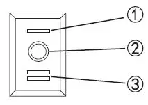
Description Of Front Board
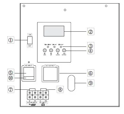
- 1. Power ON/OFF switch
- LCD display
- ED indicators
- Function keys
- Input seat
- Output seat
- Solar panels connect terminals
- Battery connect terminals
- Wire holes
- Input seat fuse
- Saver Mode
- Off Mode
- On Mode
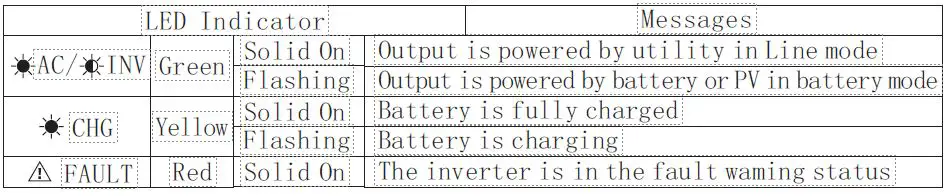
LED INDICATOR
Function Kevs
| Function Key | Description |
| ESC | To exit setting mode |
| UP | To go to previous selection |
| DOWN | To go to next selection |
| ENTER | To confirm the selection in setting mode or enter setting mode |
Function setting
Enter setting mode, Press “ENTER” button for 10 seconds.
Exit setting mode, Press “ESC” button repeatedly.
- Press up or down button to choose the parameter and then press “ENTER” button.
- When parameter is flashing, press up or down to change it and then press “ENTER” button to confirm.
- When setting: Setting icon is flashing
- Setting succeed: Left-sided frame of the parameter will flash Setting
- failed: ERROR light on
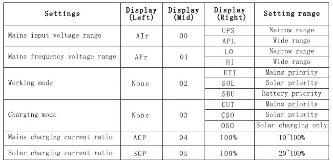
| Settings | Display (Left) | Display (Mid) | Display (Right) | Setting range |
| Boost charging voltage | cu | 06 | 14.2V | 13.5~15.0V |
| Float charging voltage | FLU | 07 | 13.6V | 12.5~14.0V |
| Battery lockdown voltage | cou | 08 | 10. 2V | 9. 5v~n. 5V |
| Charging voltage of mains recovery | OTA | 09 | 12.ov | 11. 5~12. 5V |
| Charging voltage of mains off | ATD | 10 | 13. 5V | 13.ov~14.ov |
| Inv. output voltage | OU | 11 | 220V | 200~24ov |
| Mains detection speed | CST | 12 | HI | High speed |
| IDE | Mid. speed | |||
| LO | Low speed | |||
| Inv. output frequency | OF | 13 | 50Hz | |
| 60Hz | ||||
| Fault restart switch | RA | 14 | TE | On |
| TD | Off | |||
| Backlight control | BLC | 15 | LON | Always on |
| LOF | Always off | |||
| LOD | Delay off | |||
| Buzzer control switch | BEC | 16 | AON | On |
| AOF | Off | |||
| Low battery alarm switch | BOL | 17 | OFF | Off |
| ON | On | |||
| Load limit | LL | 18 | OFF | Off |
| ON | On | |||
| Load alarm limit | LEL | 19 | OFF | Off |
| ON | On | |||
| Baud rate | BAU | 20 | 0 | 2400 |
| 1 | 4800 | |||
| 2 | 9600 | |||
| Factory | RS | OFF | Off | |
| ON | On |
Error codes for reference
| Display (Left) | Display (Right) | Details |
| ALA | 021 | Inverter communication connection failure alarm |
| ALA | 233 | Abnormal mains output alarm |
| ALA | 236 | Abnormal machine load alarm |
| ALA | 237 | Inverter overload alarm |
| ALA | 231 | Abnormal output alarm |
| ALA | 234 | High battery voltage alarm |
| ALA | 235 | Low battery voltage alarm |
| ALA | 241 | Memory chip read and write error alarm |
| ALA | 232 | Memory chip connection failure alarm |
| ALA | 238 | Inverter over temperature alarm |
| ALA | 239 | Load-causing over temperature alarm |
| ALA | 242 | Host computer software planned shutdown alarm |
| FAL | 102 | Inverter overload shutdown fault |
| FAL | 104 | Abnormal output fault |
| FAL | 105 | Abnormal load fault |
| FAL | 106 | Inverter over temperature fault |
| FAL | 135 | High battery voltage fault |
| FAL | 134 | Low battery voltage fault |
| FAL | 123 | Load-causing over-temperature fault |
| FAL | 169 | Current detection signal failure |
| FAL | 161 | Abnormal mains output fault |
| FAL | 152 | Temperature sensor connection failure |
| FAL | 162 | Host computer software planned shutdown failure |
Care and maintenance
- This inverter is low in repair rate. The battery of the standard model is valve adjusting, low maintenance, ensuring better life onlyby charging often. When connecting to mains supply, no matter inverter on or off, it still keeps charging for battery, and provide overcharge, over-discharge protection.
- If there has been long time no using, please discharge then charge the inverter each 4-6 months.
- Usually, the life span of the battery is 3-5 years. If any wrong with it, please ask professionals for changing. And do not change it by yourself.
- Don’t change the single battery, changing the battery should according to the suppliers instructions.
- Normally, the battery should discharge then recharge every four or six months, charging for it more than 12 hours after discharging.
- At high-temperature area, the battery should be discharged and charging every 2 months and the standard charging time is 12 hours at least each time.
Note:
- Before changing battery, must turn off inverter and disconnect the mains supply.
- Remove metal object like ring, watch etc.
- Please don’t put the metal objects on the battery.
- This is the normal phenomenon, when connecting the battery wire, the wiring will appear at a small spark.
- Be attentive to connecting between anode and cathode.
Rapid troubleshooting and maintenance
| Fault | Cause | Solution |
| No city power input | Recoverable fuse broken | Change the fuse |
| Terminal heating | Fault or lose connection | Fasten again |
| No Output | Battery no energy or overload | Charge the battery or reduce the loads |
| Switch on failure | Fault connection with city power or battery | Check connection with battery or connect again |
| Alarm when switching on | Battery no energy or overload | Charge the battery or reduce the loads |
| Buzzer screams every second | Over temperature alarm or low battery alarm | Check if the fan heat dissipation hole jammed |
| Fan sometimes twirls or sometimes stop | Fan twirls when inside temperature reaches 45’C, stop when 37’C | The normal phenomenon, the fan is under intelligent control |
Technical Datasheet
| MODEL | PSi400VA#12VPVT |
| Input | |
| Capacity(VA) | 400VA/250W |
| Voltage(DC) | 12V |
| Nominal Voltage | 220VAC |
| Voltage Range | 154-265VAC |
| Frequency | 50-60Hz Auto-sensing |
| Output | |
| Watt | 250W |
| Voltage | 220VAC |
| Frequency | 50/60Hz |
| Waveform | Pure sinewave |
| Transfer time(ACto DC) | <8ms |
| Transfer time( DC to AC) | <8ms |
| Output voltage regulation | 10% rms |
| Bypass Mode | Yes |
| Saver Mode | Yes |
| Efficiency | >98% |
| Battery | |
| Battery Type | AGM-Deep Cycle, GEL |
| Up to 500Ah | |
| Charging current | 9A |
| Low Level disconnect (Selectable) | 10V or 10. 5V |
|
LCD Indicator status | Input AC, Output AC |
| Battery DC, Output Load | |
| Alarm, Fault | |
| Battery Charge Level | |
| Output Frequency | |
| LED Indicator status | AC Line In: Green |
| Inverter: Green | |
| Charging: Yellow | |
| Alarm: Red | |
| Battery low alarm | battery light discharge 11. 5V*N: battery load discharge 11.5V*N@load<20% ; 11V*N@load>50%/10.5V*N@load>50%; |
| Battery low recovery | battery light discharge 12V*N; battery load discharge 12V*N@load<20%; 11.5V*N@load>50%/11V*N@load>50%; |
| DC low voltage shutdown | battery light discharge 11V*N: battery load discharge 11V*N@load<20% 10.5V*N@load>50%/10V*N@load>50% |
| DC high voltage alarm and fault | 16V*N |
| DC high voltage recovery | 15V*N |
| Optional | |
| Maximum PV array power | 800W |
| MPPT input voltage range | 15-150VDC |
| Maximum PV array open circuit voltage | 150VDC |
| Maximum solar charging current | 60A |
| Alarm | |
| Low battery alarm | The buzzer beeps once a second and stops after one minute |
| Overload alarm | The buzzer keeps beeping and stops after one minute |
| Fault | The buzzer keeps beeping and stops after one minute |
| Environment | |
| Temperature | 0-40 |
| Humidity | C0-95% , Non condensing |
| Accoustic Noise(db) | >55dB |
Appendix
How to choose and configure PV panels
The following parameters can be found in the specifications of each PV panel:
- Pmax: Maximum output power (W)
- Voc: Open circuit voltage (V)
- Isc: Short circuit current (A)
- Vpm: Rated voltage (V)
- Ipm: Rated current (A)
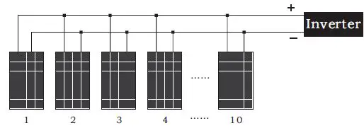
PV panels can be connected in series or in parallel to obtain the required output voltage and current to meet the allowable range of the solar controller. When connecting PV panels in series, the total maximum voltage and current is:
When the PV panels that have been connected in series are connected in parallel, the total maximum voltage and current are: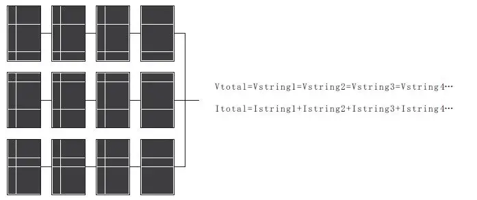
- In either case, the total output power is the power of a single PV panel X the total number of PV panels. The criteria for configuring PV panels is that the total power should be equal to or slightly greater than the maximum allowable PV power of the solar controller (please refer to the technical parameter table ). The excess capacity of PV panels does not contribute to the capacity of solar chargers and will only lead to higher installation costs.
- The total Ipm of the PV panels should be less than the maximum charging current of the inverter (60A)
- The total Voc of the PV panel should be less than the maximum PV input voltage of the inverter (please refer to the technical parameter table).
Example 1: Take a 12-inverter as an example to select suitable PV modules. - Considering that the total Voc of the PV panel cannot exceed the maximum 150VDC. The total power should be equal to or slightly greater than 800W, we can choose the following specifications of PV panels.
| Maximum power (Pmax) | 80 W | The number of PV panels connected in series for each group: MPPT→2 PCS(2*21.6V<60V) Total number of PV panels: 10PCS→800W/80W=10(PCS) A number of groups that can be connected in parallel: MPPT →5 groups (10/2 = 5 groups) |
| Rated voltage Vpm(V) | 18 V | |
| Rated current Ipm(A) | 4 . 46 A | |
| Open circuit voltage Voc(V) | 21 . 6 V | |
| Short circuit current Isc(A) | 4 . 8 A |
The configuration scheme of the 12 V inverter is:
Every 2 PV panels are connected in series to form a group, and connected to 5 groups of PV panels.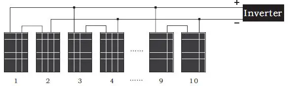
10 PV panels are connected in parallel to the inverter.