 APD0826 / 2021 / ISSUE 3
INSTALLATION GUIDE
SOTERIA UL
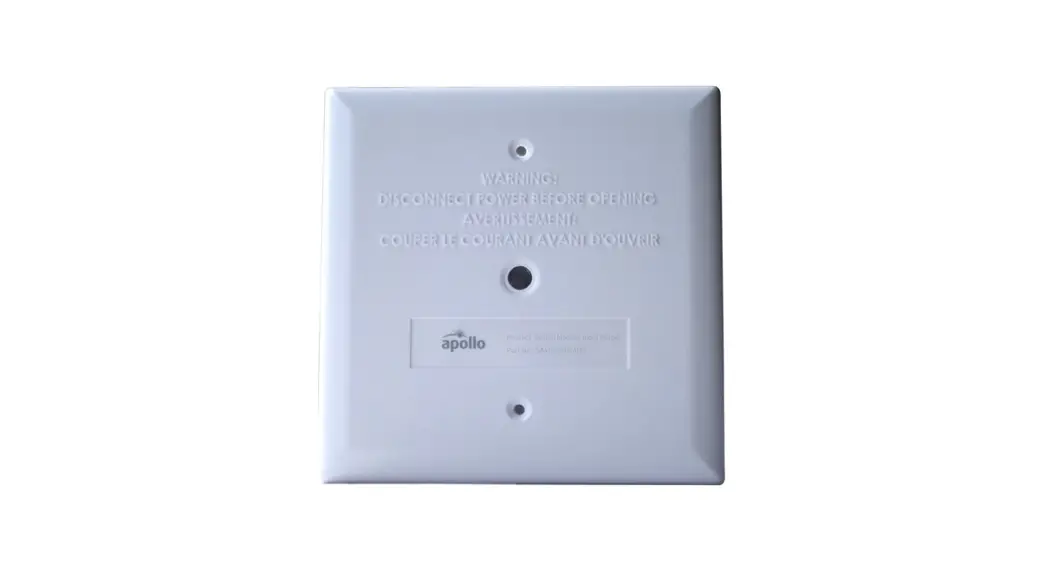
SWITCH MONITOR MODULE
GENERAL
The Switch Monitor Module is a loop-powered device that incorporates a separately addressed monitored input circuit for connection to a remote switch. It has a selectable ‘priority interrupt’ to give a fast response from devices such as pull stations. It is mounted with a plastic fascia plate for use with a UL listed 4” electrical box or dual gang.
Please Note:
- When the 10th section of the dip switch is changed, the Switch Monitor Module will change the type code it sends to the panel in XP95/Discovery Protocol.
- The Switch Monitor Module is designed for indoor dry use only .
- All circuits are power limited.
- The unit must be installed in a dedicated suitable UL listed enclosure, employing only power limited circuit.
CONTROL PANEL COMPATIBILITY
The Switch Monitor Module has been approved by UL, LLC. For details of compatible panels contact Apollo America Inc.
TECHNICAL INFORMATION
All data is supplied subject to change without notice. Specifications are typical at 24V, 25°C and 50% RH unless otherwise stated.
| Part Number | SA4705-700APO |
| Replacement Part Number | 55000-805,55000-806 |
| Type | Switch Monitor Module |
| Dimensions | 4.9” width x 4.9” height x 1.175” depth |
| Temperature Range | 32°F to 120°F (0°C to 49 °C) |
| Humidity | 0 to 95% RH (Non-Condensing) |
| Signal Line Circuit (SLC) | Supervised |
| Operating Voltage | 17-28V DC |
| Modulation Voltage | 5-9 V (peak to peak) |
| Supervisory Current | <700 µA |
| LED Current | 1.6mA per LED |
| Maximum Loop Current | 1A |
| Approvals | UL, ULC, CSFM, FM |
| Material | UL 94 V-0 |
| Max Standby Current (Pulsing LED) | 2.96 mA |
| Max Surge Alarm Current (LEDs on) | 4.8 mA |
| Wire Range | 12-24 AWG |
TECHNICAL INFORMATION COUNT.
| Initiating Device Circuit (IDC) | |
| Wiring Styles | Supervised power limited Class A and Class B |
| Voltage | 3.3 V DC (<200 µA) |
| Line Impedance | 100 Ω max |
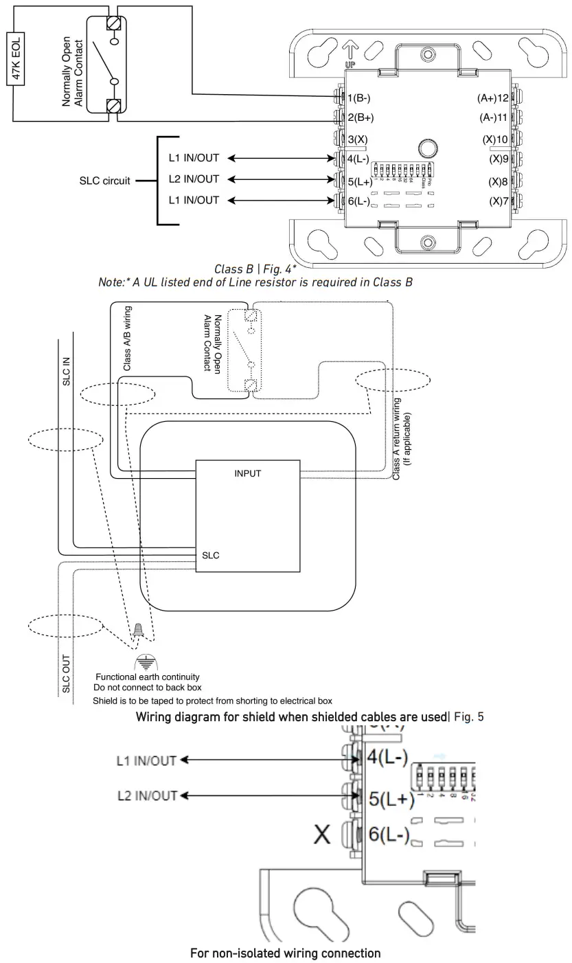
End-of-Line resistors* 47k Ω
Note: *A UL listed end-of-line resistor is available at Apollo, Part no. 44251-146
| Analogue Values | ||
| Without Ground Fault | With Ground Fault* | |
| Normal | 16 | 19 |
| Alarm | 64 | 64 |
| Trouble | 4 | 4 |
Note: * Ground fault values need to be enabled by the dip switch (by Default no ground Fault values will show up).
INSTALLATION
This product must be installed in accordance with the applicable NFPA standards, local codes and jurisdictional authorities. Failure to follow these instructions may result in failure of devices to report an alarm condition. Apollo America Inc. is not responsible for devices which are improperly installed, maintained and tested.
Before installing this product, check the continuity, polarity and insulation resistance of all wiring. Check that wiring is in accordance with the fire system drawings and conforms to all applicable local codes such as NFPA 72.
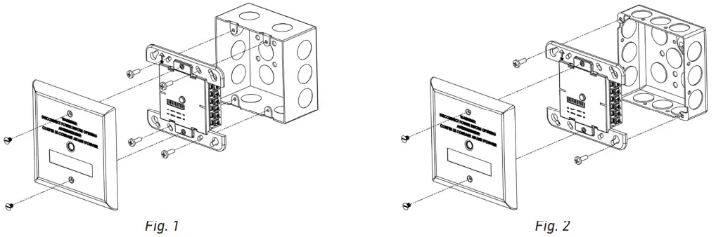
- Mount the electrical box as required and install all cables for termination.
- Terminate all cables in compliance with local codes and regulation. Ensure that cable shield/ earth continuity is maintained and no short occurs with the back box (see Fig. 3 and 4 for wiring instructions)
- Set the address on dip switch of the unit as shown on page 5.
- Gently push the completed assembly towards the mounting box and verify wiring and address. Align the fixing holes.
- Secure the module to the electrical box with provided screws. Do not over tighten screws.
- Place the face plate over the module and secure with provided screws.
- Commission the module.
WIRING INSTRUCTION
Note: ‘X’ denotes unused terminals
CAUTION: When Making Installation, Route Field Wiring Away From Sharp Projections, Corners, and Internal Components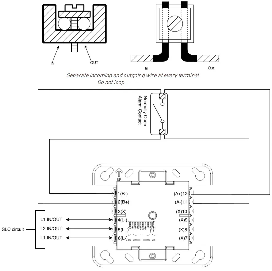
ADDRESS SETTING
Steps:
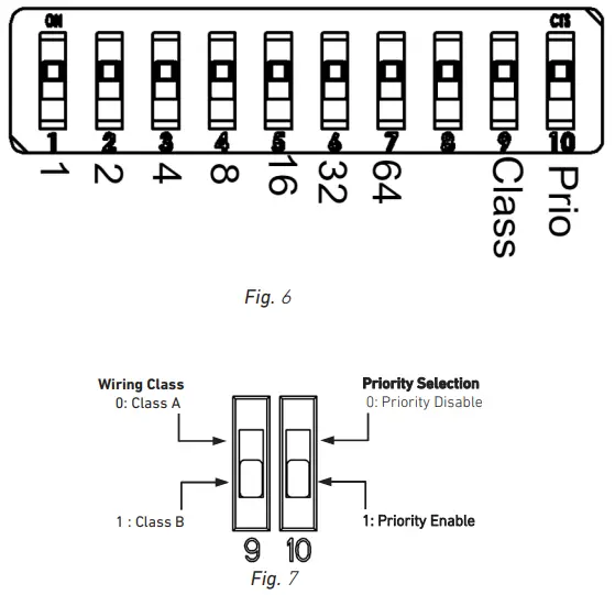
- The dip switch used to address your device has 10 individual switches (Figure 6).
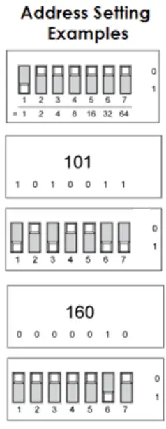
- Address setting is done by dip switches 1-8 (see page 7 for address matrix).
a. In XP/Discovery Protocol, only dip switch 1-7 are used, dip switch 8 is used to enable ground fault analogue value.
b. Dip switch down = 1 and up = 0. - Dip switch 9 is used to set Wiring Class A/B (Figure 7).
- Dip switch 10 is used for setting the priority on the modules (Figure 7).
a. Priority selection is only available on SA4705-600APO, SA4705-700APO, SA4705-703APO, SA4705-720APO.
LED STATUS
| LED Color | Description |
| Green | Polling |
| Yellow (Solid) | Isolation |
| Red | Command Bit |
A green LED flashes in synchronization with the current pulse reply from the device.
ADDRESS MATRIX
| 1 | 1000 0000 | 43 | 1101 0100 | 85 | 1010 1010 |
| 2 | 0100 0000 | 44 | 0011 0100 | 86 | 0110 1010 |
| 3 | 1100 0000 | 45 | 1011 0100 | 87 | 1110 1010 |
| 4 | 0010 0000 | 46 | 0111 0100 | 88 | 0001 1010 |
| 5 | 1010 0000 | 47 | 1111 0100 | 89 | 1001 1010 |
| 6 | 0110 0000 | 48 | 0000 1100 | 90 | 0101 1010 |
| 7 | 1110 0000 | 49 | 1000 1100 | 91 | 1101 1010 |
| 8 | 0001 0000 | 50 | 0100 1100 | 92 | 0011 1010 |
| 9 | 1001 0000 | 51 | 1100 1100 | 93 | 1011 1010 |
| 10 | 0101 0000 | 52 | 0010 1100 | 94 | 0111 1010 |
| 11 | 1101 0000 | 53 | 1010 1100 | 95 | 1111 1010 |
| 12 | 0011 0000 | 54 | 0110 1100 | 96 | 0000 0110 |
| 13 | 1011 0000 | 55 | 1110 1100 | 97 | 1000 0110 |
| 14 | 0111 0000 | 56 | 0001 1100 | 98 | 0100 0110 |
| 15 | 1111 0000 | 57 | 1001 1100 | 99 | 1100 0110 |
| 16 | 0000 1000 | 58 | 0101 1100 | 100 | 0010 0110 |
| 17 | 1000 1000 | 59 | 1101 1100 | 101 | 1010 0110 |
| 18 | 0100 1000 | 60 | 0011 1100 | 102 | 0110 0110 |
| 19 | 1100 1000 | 61 | 1011 1100 | 103 | 1110 0110 |
| 20 | 0010 1000 | 62 | 0111 1100 | 104 | 0001 0110 |
| 21 | 1010 1000 | 63 | 1111 1100 | 105 | 1001 0110 |
| 22 | 0110 1000 | 64 | 0000 0010 | 106 | 0101 0110 |
| 23 | 1110 1000 | 65 | 1000 0010 | 107 | 1101 0110 |
| 24 | 0001 1000 | 66 | 0100 0010 | 108 | 0011 0110 |
| 25 | 1001 1000 | 67 | 1100 0010 | 109 | 1011 0110 |
| 26 | 0101 1000 | 68 | 0010 0010 | 110 | 0111 0110 |
| 27 | 1101 1000 | 69 | 1010 0010 | 111 | 1111 0110 |
| 28 | 0011 1000 | 70 | 0110 0010 | 112 | 0000 1110 |
| 29 | 1011 1000 | 71 | 1110 0010 | 113 | 1000 1110 |
| 30 | 0111 1000 | 72 | 0001 0010 | 114 | 0100 1110 |
| 31 | 1111 1000 | 73 | 1001 0010 | 115 | 1100 1110 |
| 32 | 0000 0100 | 74 | 0101 0010 | 116 | 0010 1110 |
| 33 | 1000 0100 | 75 | 1101 0010 | 117 | 1010 1110 |
| 34 | 0100 0100 | 76 | 0011 0010 | 118 | 0110 1110 |
| 35 | 1100 0100 | 77 | 1011 0010 | 119 | 1110 1110 |
| 36 | 0010 0100 | 78 | 0111 0010 | 120 | 0001 1110 |
| 37 | 1010 0100 | 79 | 1111 0010 | 121 | 1001 1110 |
| 38 | 0110 0100 | 80 | 0000 1010 | 122 | 0101 1110 |
| 39 | 1110 0100 | 81 | 1000 1010 | 123 | 1101 1110 |
| 40 | 0001 0100 | 82 | 01001010 | 124 | 0011 1110 |
| 41 | 1001 0100 | 83 | 1100 1010 | 125 | 1011 1110 |
| 42 | 0101 0100 | 84 | 0010 1010 | 126 | 0111 1110 |
Notes:
- For XP95/Discovery Protocol only panels address is only limited from 1-126.
- Dip Switch 8 is used to enable the ground fault detection on XP95/Discovery Protocol only.
Apollo America Inc.
30 Corporate Drive, Auburn Hills, MI 48326
Tel: (248) 332-3900. Fax: (248) 332-8807
Email: [email protected]
www.apollo-fire.com
All information in this document is given in good faith but Apollo America Inc. cannot be held responsible for any omissions
or errors. The company reserves the right to change the specifications of products at any time and without prior notice.
A Halma compny
© 2020 Apollo America Inc.


 Installation Guide")


