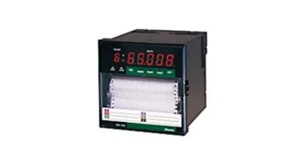
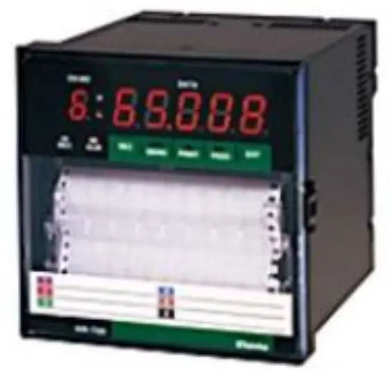
Shinko HR-700 Hybrid Recorder
INTRODUCTION
General Description
This instruction manual describes the communication command of the HR-700 Recorder. Please refer to the instruction manual for the transmission of the measurement data, setup of communication and wiring. Modbus RTU protocol as well as Original protocol can be used from version 4.00.
| Contents | Wiring and communication procedure | Request measurement value | Setting of the recorder | Control of the recorder |
| HR-700 Hybrid Recorder instruction manual | O | O | ||
| HR-700 Hybrid Recorder Communication Command manual | O | O |
O: Please refer to the corresponding manual.
Difference between RS-485 and RS-232C
There is no difference between RS-232C and RS-485 with respect to the communication command in this recorder. However, wiring and signal levels may differ.
There is no difference between RS-232C and RS-485 with respect to the communication command in this recorder. However, wiring and signal levels may differ.
Basic item about the Original protocol command
The communication command consists of a command distinction code, a parameter, delimiter (comma), and terminator. The format of the command is as follows.
(Example) SR02 VOLT, 200mV, 0, 20000 (terminator)
Command distinction code:
This code is defined by two capital letters. (e.g. SR)
If the command needs a channel number, the channel number is described after the distinction code.
Parameter:
Each parameter is divided by a comma.
All the setting values are shown with an integer. (The plus sign can be omitted.)
The space character in the input parameter is ignored. However, the space character in the unit code, the comment printout code and the tag printout code are not ignored. Parameters can be omitted unless the parameters are varied. However, the comma (,) cannot be omitted. Commas which come before the terminator can be omitted.

The date parameter, the time parameter and the channel number parameter have fixed length. Different length of these parameters may cause errors.
- Date YY/MM/DD (8 characters)
- Time HH:MM:SS (8 characters)
- Channel Number: CHXX (2 characters)
Basic item about the Modbus RTU protocol
Modbus protocol is a communication protocol which was developed for PLC by Modicon Inc. (AEG Schneider Automation International SAS), and is listed in the protocol specification (PI-MBUS-300 Rev.J).
Regarding the Modbus protocol specification, refer to the protocol specification (PI-MBUS-300 Rev.J).
In this manual, we describe the function codes and data contents of Modbus protocol which can be used for the recorder.
ORIGINAL PROTOCOL – DATA RECEPTION
Setup command
Setup command list
Table 2.1.1 Setup command list
| Command | Setting item | Number of parameters | Contents of parameter |
| SR | Setting the range | MAX 7 | Channel, Mode, Range (Reference Channel) Span lower limit value Span upper limit value Scaling lower limit value Scaling upper limit value |
| SA | Setting the Alarm | 7 | Channel Alarm level Alarm ON/OFF Alarm type, Alarm set point Relay ON/OFF, Relay No. |
| SN | Setting the Unit | 2 | Channel, Unit |
| SC | Setting the Chart Speed | 1 | 1st Chart speed |
| SD | Setting the Date/Time | 2 | Date, time |
| SF | Setting the Digital Print | 2 | Channel Digital print ON/OFF |
| ST | Setting the Tag | 2 | Channel, Tag characters |
| SG | Setting the Comment | 2 | Comment number Comment characters |
| SZ | Setting the Zone recording | 3 | Channel Left end position Right end position |
| SP | Setting the Partial Compression/Expansion recording | 4 | Channel, Partial ON/OFF Compression Expansion |
| SE | Setting the Chart Speed | 1 | 2nd chart speed |
| SY | Copying the Setting data | 2 | Channel to copy from Channel to copy to |
| SS | Setting the recording cycle | 1 | Recording Cycle (Multipoint type only) |
Setting of INPUT RANGE/RECORD SPAN
Sets the input range and record span for each channel as follows.
<Format>
SR(CH), (Mode), (Pr1), (Pr2), (Pr3), (Pr4), (Pr5), (Pr6), (Pr7), (CR)(LF)
CH: Specify a channel number to set.
Mode: Mode setting
PrN: The number of PrN varies depending on the contents of the Mode.
- Record skip setting
The record of the specified channel (CH) stops.
[For the pen type recorder, No. 1 pen (red) is fixed on the left side (approx. 15%) and No. 2 pen (green) on the right side (approx. 85%), respectively.]
CH: Setting Channel 01 to 06 (01 and 02 for the pen type)
Mode: SKIP
Example) SR05,SKIP(CR)(LF)
The 5th channel doesn’t record. - Input range setting of the Voltage, Current, Thermocouple and RTD
CH: Setting Channel 01 to 06 (01 and 02 for the pen type)
Mode: VOLT, TC or RTD Example)SR02,TC,K,0,3000(CR)(LF)
The input of the 2nd channel is Thermocouple K, 0.0-300.0 - Difference/Sum/Mean operation setting.
CH: Setting Channel 01 to 06 (01 and 02 for the pen type)
Mode: DELT,SIGM or MEAN
Pr1: Reference Channel- Choose a smaller channel than CH.
- The reference channel must be VOLT, TC, RTD or SCL mode.
 Pr2: Left end (Zero Input Value)
Refer to Table 2.1.2.
Pr3: Right end (Span Input Value)
Example) SR05,02,DELT,0,3000(CR)(LF)
The output of the 5th channel shows a difference between the input of the 5th channel and the 2nd channel (CH5-CH2). In this case, the input range of the 5th channel is the same as that of the 2nd channel.
- Scaling setting
CH: Setting Channel 01 to 06 (01 and 02 for the pen type)
Mode: SCL
Pr1: VOLT, TC, RTD
Pr4: Right End (Span Input Value)
Pr5: Scaling Left End
Pr6: Scaling Right End
Pr7: Decimal point position (0 to 4)
Example) SR04,SCL,RTD,PT,0,3000,0,30000,2(CR)(LF)
[CAUTION]
Pr5 through Pr7 can be omitted. When omitting parameters, three parameters must be omitted simultaneously. - Square Root setting
CH: Setting Channel 01 to 06 (01 and 02 for the pen type)
Mode: SQRT
Pr1: Range (Only VOLT Input) Pr4: Scaling Left End
Pr5: Scaling Right End
Pr6: Decimal point position (0 to 4)
Example) SR03,SQRT,mA,400,2000,0,10000,2(CR)(LF)
[CAUTION]
Pr5 through Pr7 can be omitted. When omitting parameters, three parameters must be omitted simultaneously. - Decade setting
CH: Setting Channel 01 to 06 (01 and 02 for the pen type)
Mode: DECAD
Pr1: Range (Only VOLT Input) Pr4: Scaling Left End
Pr5: Scaling Right End
Example) SR01,DECAD,10mV,0,1000,10E+01,10E+06(CR)(LF)
 Example)SR02,TC,K,0,3000(CR)(LF)
 Pr2: Left end (Zero Input Value)
 Pr4: Scaling Left End
 Pr4: Scaling Left End
Table 2.1.2 Setting range
| Input Range | Range or Scaling Mode | Zero Input Value (Left End) | Span Input Value (Right End) | Decima Point (Fixed) | Note |
| VOLT | 10mV | -1000 | 1000 | 2 | 10mV |
| 20mV | 0 | 2000 | 2 | 0 to 20mV | |
| 50mV | 0 | 5000 | 2 | 0 to 50mV | |
| 200mV | -2000 | 2000 | 1 | 200mV | |
| 1V | -1000 | 1000 | 3 | 1V | |
| 5V | 0 | 5000 | 3 | 0 to 5V | |
| 10V | -10000 | 10000 | 2 | 10V | |
| mA | 400 | 2000 | 2 | 4 to 20mA | |
| TC | B | 0 | 18200 | 1 | 0 to 1820 |
| 320 | 33080 | 1 | 32 to 3308 | ||
| R | 0 | 17600 | 1 | 0 to 1760 | |
| 320 | 32000 | 1 | 32 to 3200 | ||
| S | 0 | 17600 | 1 | 0 to 1760 | |
| 320 | 32000 | 1 | 32 to 3200 | ||
| K | -2000 | 13700 | 1 | -200 to 1370 | |
| -3280 | 24980 | 1 | -328 to 2498 | ||
| E | -2000 | 8000 | 1 | -200 to 800 | |
| -3280 | 14720 | 1 | -328 to 1472 | ||
| J | -2000 | 11000 | 1 | -200 to 1100 | |
| -3280 | 20120 | 1 | -328 to 2012 | ||
| T | -2000 | 4000 | 1 | -200 to 400 | |
| -3280 | 7520 | 1 | -328 to 752 | ||
| C | 0 | 23200 | 1 | 0 to 2320 | |
| 320 | 42080 | 1 | 32 to 4208 | ||
| Au-Fe | 10 | 3000 | 1 | 1 to 300K | |
| N | 0 | 13000 | 1 | 0 to 1300 | |
| 320 | 23720 | 1 | 32 to 2372 | ||
| PR40-20 | 0 | 18800 | 1 | 0 to 1880 | |
| 320 | 34160 | 1 | 32 to 3416 | ||
| PL- | 0 | 13900 | 1 | 0 to 1390 | |
| 320 | 25340 | 1 | 32 to 2534 | ||
| U | -2000 | 4000 | 1 | -200 to 400 | |
| -3280 | 7520 | 1 | -328 to 752 | ||
| L | -2000 | 9000 | 1 | -200 to 900 | |
| -3280 | 16520 | 1 | -328 to 1652 | ||
| RTD | Pt100 | -2000 | 6500 | 1 | -200 to 650 |
| -3280 | 12020 | 1 | -328 to 1202 | ||
| JPt100 | -2000 | 6300 | 1 | -200 to 630 | |
| -3280 | 11660 | 1 | -328 to 1166 |
Example) When decimal point position is “1”, the input value “1000” is recognized as “100.0”.
Setting of the Alarm
Sets Alarm for each channel as follows.
<Format>
SA(CH), (LEVEL), (ON/OFF), (TYPE), (VALUE), (RLY ON/OFF), (RLY No.) (CR)(LF)
| Item | Contents | Setting Range | Note |
| CH | Channel number | 01 to 06 (multi) 01 to 02 (pen) | |
| LEVEL | Alarm level | 1 to 4 | |
| ON/OFF | Alarm ON/OFF | ON or OFF | Can be omitted. |
| TYPE | Alarm Type | H:Upper-limit L:Lower-limit | Can be omitted. |
| VALUE | Set Value | Can be omitted. | |
| RLY ON/OFF | Relay ON/OFF | ON or OFF | Can be omitted. |
| RLY No. | Relay No. | I01 to I06 (multi) I01 to I03 (pen) | Can be omitted. |
The underlined part can be omitted.
Setting of the Unit
Sets the Unit for each channel as follows.
<Format>
SN(CH),(UNIT)(CR)(LF)
CH: Setting Channel 01 to 06 (01 and 02 for the pen type)
UNIT: The Unit can be set with cods as shown in Table 2.1.13 (Within 6 characters).
When you use the code beyond 7FHEX, 8-bit data length must be used. Please refer to Section 7.2.7 of the instruction manual (HR-700) for the data length setting.
Setting of the 1st chart speed
Sets the 1st chart speed as follows.
<Format>
SC (CHART SPEED) (CR) (LF)
A chart speed is chosen from the following table.
CHART SPEED (Dot printing type)
| 0 | 1 | 2 | 3 | 4 | 5 | 10 | 15 | 20 | 25 |
| 30 | 40 | 50 | 60 | 75 | 80 | 90 | 100 | 120 | 150 |
| 160 | 180 | 200 | 240 | 300 | 360 | 375 | 450 | 600 | 720 |
| 750 | 900 | 1200 | 1500 | ||||||
CHART SPEED (Pen type)
| 5 | 10 | 15 | 20 | 25 | 30 | 40 | 50 | 60 | 75 |
| 80 | 90 | 100 | 120 | 150 | 160 | 180 | 200 | 240 | 300 |
| 360 | 375 | 450 | 600 | 720 | 750 | 900 | 1200 | 1500 | 1800 |
| 2400 | 3000 | 3600 | 4500 | 4800 | 5400 | 6000 | 7200 | 9000 | 10800 |
| 12000 | |||||||||
Setting of the date/time
Sets date/time of the internal clock of the recorder as follows.
<Format>
SD(DATE),(TIME)(CR)(LF)
DATE: YY/MM/DD
(YY) Year 00 to 99
(MM) Month 01 to 12
(DD) Day 01 to 31
TIME: HH:MM:SS
(HH) Hour 00 to 23
(MM) Minute 00 to 59
(SS) Second 00 to 59
Copying the Setting Data of the channel
The setup data of any channel can be copied to another channel.
<Format>
SY(CHS),(CHD) (CR)(LF)
CHS: Channel to copy from, 01 to 05 (Only 01 for the Pen type)
CHD: Channel to copy to (CHS < CHD)
The number of the channel to be copied must be bigger than the channel to copy from.
Setting of the Printing cycle (Dot printing type only)
Sets Printing cycle of the recorder as follows.
<Format>
SS(PRINTING CYCLE)(CR)(LF)
PRINTING CYCLE: 10, 20, 30 and 60 (sec.)
Setting of the Zone Recording
Sets Zone Recording of each channel as follows.
<Format>
SZ(CH),(LEFTPOSITION),(RIGHTPOSITION)(CR)(LF)
CH: Setting Channel 01 to 06 (01 and 02 for the pen type)
LEFT POSITION: 0 to 95%
RIGHT POSITION: 5 to 100%
The underlined parts can be omitted.
Setting of the Partial Compression/Expansion
Sets Partial Compression/Expansion recording of each channel as follows.
<Format>
SP(CH),(ON/OFF),(BOUNDARY POSITION),(BOUNDARY VALUE)(CR)(LF)
CH: Setting Channel 01 to 06 (01 and 02 for the pen type)
ON/OFF: Partial Compression/Expansion function ON or OFF
BOUNDARY POSITION: 1 to 99%
BOUNDARY VALUE:
CH is VOLT, TC, RTD, DELT, SIGM or MEAN mode: In the span data
CH is SCALE, SQRT, DECAD mode: In the scale data
The underlined part can be omitted.
Setting of the Digital Print ON/OFF
Sets Digital Print ON/OFF of each channel as follows.
<Format>
SF(CH),(ON/OFF)(CR)(LF)
CH: Setting Channel 01 to 06 (01 and 02 for the pen type)
ON/OFF: ON or OFF
Setting of the Tag Character
Sets Tag Character of each channel.
<Format>
ST(CH),(TAG)(CR)(LF)
CH: Setting Channel 01 to 06 (01 and 02 for the pen type)
TAG: The Tag Character can be set with character codes shown in Table 2.1.13.
(Dot printing type is within 7 characters. Pen type is within 5 characters.)
When you use the character code beyond 7FHEX, 8-bit data length of communication function must be used.
Please refer to Section 7.2.7 of the instruction manual (HR-700) for the data length setting.
Setting of the Comment Character
Sets Comment Character to be printed by the Digital Input.
<Format>
SG(Cn),(COMMENT)(CR)(LF)
Cn: Comment Number(1 to 3)
COMMENT: A Comment Character is set up with the character code shown in Table 2.1.13.
(Dot printing type is within 16 characters. Pen type is within 12 characters.) When you use the character code beyond 7FHEX, the data length of communication function must be used as 8 bits.
Please refer to Section 7.2.7 of the instruction manual (HR-700) for the data length setting.
Character Code Table
Table 2.1.13 Character Code Table
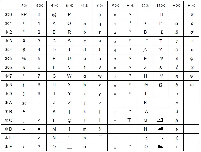
Example) The character code “43HEX” represents as the character “C”.
Control command
Control command list
Table 2.2.1 Control command list
| Command | Control item | Number of parameters | Explanation of operation |
| PS0 | Recording Start | – | The same as the recording by the RUN key. |
| PS1 | Recording Stop | – | |
| MP0 | Manual Print start | – | The same as the manual print by key operation |
| MP1 | Manual Print stop | – | |
| LS0 | List Print start | – | The same as the List Print by key operation |
| LS1 | List Print stop | – | |
| SU0 | Engineering List Print start | – | The same as the Engineering List Print by key operation. |
| SU1 | Engineering List Print stop | – | |
| UD0 | Auto Display selection | – | When the manual display is selected, channel number can be set. However, the channel number can be omitted. (e.g.)Displaying the measurement value of the 5th channel: UD1, 05 (CR)(LF) |
| UD1 | Manual Display selection | 1 | |
| UD2 | Date Display selection | – | |
| UD3 | Time Display selection | – | |
| UD4 | Display OFF selection | – | |
| PR0 | Communication comment print out (Sync printout) | 2 | Prints out characters received by the communication function. The parameter consists of printout colors and printout characters. |
| PR1 | Communication comment print out (Async printout) | 2 | |
| BO0 | Byte output order (High byte earlier) | 2 | This command is valid only in the binary mode. (Please refer to Chapter 8 of the instruction manual for details.) |
| BO1 | Byte output order (Low byte earlier) | 2 | |
| TS0 | Measurement value output | – | The recorder sets output information in the memory, and returns the corresponding data after “ESC T” command is received. (Please refer to Chapter 8 of the instruction manual for details.) |
| TS1 | Setting value output. (Refer to Chapter 3) | – | |
| TS2 | Decimal point position and the unit character output. (Refer to Chapter 3) | – | |
| FM0 | The ASCII mode output of the measurement data | 2 | This command outputs the measurement value. The parameter consists of the output start channel and output end channel. (Please refer to Chapter 8 of the instruction manual for details.) |
| FM1 | The Binary mode output of the measurement data | 2 | |
| LF | The output of the setting value, the unit character and the decimal point position | 2 | This command outputs the setting value. The parameter consists of the output start channel and output end channel. (Please refer to Chapter 8 of the instruction manual for details.) |
Recording Start/Stop
This command starts or stops recording.
<Format>
PS0(CR)(LF): The recorder starts recording.
PS1(CR)(LF): The recorder stops recording.
Manual Print Start/Stop
This command starts or stops the Manual print.
<Format>
MP0(CR)(LF): The manual print starts.
MP1(CR)(LF): The manual print stops.
List Print Start/Stop
This command starts or stops the List print.
<Format>
LS0(CR)(LF): The list print starts.
LS1(CR)(LF): The list print stops.
Engineering list Print Start/Stop
This command starts or stops the Engineering list print.
<Format>
SU0(CR)(LF): The Engineering list print starts.
SU1(CR)(LF): The Engineering list print stops.
Selection of the display contents
This command selects the display mode of the recorder.
The Auto Display, the Manual Display, the Date Display, the Time Display and Display OFF can be chosen.
When receiving this command, the display of the recorder changes automatically.
<Format>
- UD0(CR)(LF) : Auto Display
- UD1, (CH)(CR)(LF) : Manual Display
- UD2(CR)(LF) : Date Display
- UD3(CR)(LF) : Time Display
- UD4(CR)(LF) : Display OFF
CH: The manual display channel 01 to 06 (01 and 02 for the pen type)
The underlined part can be omitted.
Communication comment print out
This command prints the character strings, which have been received by the communication function. Please refer to Table 2.1.13 for the character code. When you use the character code beyond 7FHEX, 8-bit data length of communication function must be used.
Please refer to Section 7.2.7 of the instruction manual (HR-700) for the data length setting.
<Format>
- PR0, (COLOR), (TEXT)(CR)(LF): Sync printout
- PR1, (COLOR), (TEXT)(CR)(LF): Async printout
- COLOR: Chooses a printout color. (The Pen type has only PRP.)
- PRP: Purple, RED: Red, BLK: Black, GRN: Green, BRN: Brown, BLU: Blue
- TEXT: Maximum character number for the Dot printing type is 47.
- Maximum character number for the Pen type is 21.
ORIGINAL PROTOCOL – DATA TRANSMISSION
Setting Value Reading
When the recorder receives “(TS1)+ (ESC T) + (LF)”, the recorder continuously sends the setting value according to Table 3.1 below.
The output format of each command when reading is the same as that of when setting.
Table 3.1 Order of the setting value transmission
Send the setting value in this order
| Order | Command | Description |
| 1 | PS | Recording start/ Recording stop |
| 2 | SR | Input range, recording span |
| 3 | SN | Unit |
| 4 | SA | Alarm |
| 5 | SC | 1st chart speed |
| 6 | SS | Analog printing period (only for Dot printing type) |
| 7 | SZ | Zone recording |
| 8 | SP | Partial compression/expansion recording |
| 9 | SF | Digital printing |
| 10 | ST | Tag character |
| 11 | SG | Comment character |
| 12 | SE | 2nd chart speed |
| 13 | UD | Display indication mode |
| 14 | EN | End |
Data Reception Example
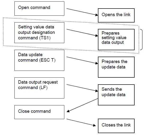
- Send the command to the recorder which starts data transmission.
- Designates setting value data to send when the recorder receives ESC T command once.
- The designated data remains unchanged until the recorder receives TS0 and TS2 commands.
- Send this command to the recorder when transmitting data to another recorder.
ORIGINAL PROTOCOL – NOTES FOR COMMUNICATION
Half-Duplex Transmission
Half-duplex transmission is used for the recorder side. The recorder cannot receive data while it is sending data.
When sending the command, the host computer should send the next command after it received data from the recorder.
Multiple access
Do not open another recorder when one recorder is open on the same line.
Continuation of Opening the Link
Do not allow an extended interval after sending the open command. A syntax error may occur when not sending data. Be sure to send the close command “ESC C” when you do not use communication function. If a syntax error occurs, send the status output command ” ESC S” to reset the error.
(The close command cannot reset syntax errors.)
Outputting the Status
When the open-link recorder has a data error on its link, the recorder saves the error in the internal status area as a communication error. The “ESC S” command reads this status. Issuing this command clears the on-going error. Refer to Section 8.5 in the instruction manual (HR-700).
Be sure to reset the error when setting data to the recorder. If the error is not reset, you may not be able to assess which command caused errors.
MODBUS RTU PROTOCOL – OVERVIEW
Modbus RTU protocol
| Item | Specification |
| Interface | RS-485/RS-232C |
| Protocol | Modbus RTU |
| Communication speed | 1200 /2400 /4800 /9600 /19200/ 38400 [bps] |
| Parity | None/Even/Odd |
| Data length | 8bit(※) |
| Stop bit | 1bit / 2bit |
| Slave address | 1~247(0 invalid) |
Please use 8bit data length when using the Modbus RTU protocol.
Communication can’t be performed successfully if you use 7bit.
Adding new items and Map version
Depending on the version up of the recorder, there is that the contents of the Modbus map is hanged.
If the Modbus map is modified, Modbus map version (address 30025) will also be updated.
Newly added setting items are available in the corresponding version or later. (Table below)
| Body version | Map version | Contents | Note |
| before Ver4.00 | - | Modbus RTU is not available. | |
| Ver4.00 | 01 | The first release of the Modbus RTU function. |
[CAUTION]
In the old version, you can’t use features added in the new version.
In that case, there is a possibility that it does not work properly when reading / writing to the address of the newly added function.
MODBUS RTU PROTOCOL – DATA TRANSMISSION AND RECEPTION
Communication protocol
This equipment is compatible with Modbus RTU protocol.
Data format of the protocol is as below. It is composed of slave address, function code, data, and CRC section.
Modbus RTU Data format
| Slave address (1byte) | Function code (1byte) | Data (variable) | CRC (2byte) |
Function codes
Function code that can be used in this equipment is as follows.
| Code | Function | Maximum data length | Modbus original function (reference) |
| 03H | Setting data read | 123 words | Data read from holding register |
| 04H | Input data read | 123 words | Data read from input register |
| 06H | One-time setting data write | 1 words | Data write to holding register |
| 10H | Continuous setting data writes | 123 words | Data write to holding register |
Error response
In accordance with the communication protocol for the pertinent function code, if an error occurs during command transmission, an error response is returned in the fixed format described in this section.
- Example of slave response (function code = 06H, command error = 10H)
Configuration Data length Data Slave address 1 - Function code + 80H 1 86H Error code 1 10H Error check (Only for Modbus RTU) 2 CRC Total number of bytes 5 - - Error codes and their occurrence conditions.
Error code Description Occurrence condition(s) 01H Invalid function code An unsupported function code is specified. 02H Invalid register address The relative address range exceeds “9999.” 03H Invalid number of registers - The length of the accessed data is “0” or the sum of the relative address and data length exceeds the limit.
- It is assumed that two or more function codes, each executable for one area, are involved.
- Data longer than 2 words is specified for a one-time write command.
- The data length exceeds 123 words.
04H Device error The received data is shorter than the predefined data length. 10H Command error An attempt at a write over an area exceeding the writable range.
Reading of input register area
The input register area is a read-only area.
The current measured value and the current time are mapped. Specify the start
address (relative) and data count (assuming that one word is two bytes) of the data to be read.
Reading of input register area
Function code :04H
- Example of master transmission (with a start address of 0032H and a data count of 2 words)
Component Data length Data Slave address 1 - Function code 1 04H Data Relative start address (high-order) 1 00H Relative start address (low-order) 1 32H Read data count (high-order) 1 00H Read data count (low-order) 1 02H Error check 2 CRC (16 bits) Total number of bytes 8 - Example of slave response (with a start address of 0032H and a data count of 2 words)
Component Data length Data Slave address 1 - Function code 1 04H Data Number of data bytes 1 04H Data 1 (high-order) 1 00H Data 1 (low-order) 1 09H Data 2 (high-order) 1 00H Data 2 (low-order) 1 0AH Error check 2 CRC (16 bits) Total number of bytes 9
Input Register Area Map
【Input Register Area Map】 Function code: 04H
| Address | Relative address (HEX) | Name | Array | Content | Remarks |
| 30001 | 0 | Model type(1/8) | 1 | ASCII | Multipoint type :”MULTI” |
| 30002 | 1 | Model type(2/8) | 2 | Pen type :”PEN” | |
| 30003 | 2 | Model type(3/8) | 3 | After the blank | |
| 30004 | 3 | Model type(4/8) | 4 | ||
| 30005 | 4 | Model type(5/8) | 5 | ||
| 30006 | 5 | Model type(6/8) | 6 | ||
| 30007 | 6 | Model type(7/8) | 7 | ||
| 30008 | 7 | Model type(8/8) | 8 | ||
| 30009 | 8 | Software version(1/16) | 1 | ASCII | Version information on a system. |
| 30010 | 9 | Software version(2/16) | 2 | ||
| 30011 | A | Software version(3/16) | 3 | ||
| 30012 | B | Software version(4/16) | 4 | ||
| 30013 | C | Software version(5/16) | 5 | ||
| 30014 | D | Software version(6/16) | 6 | ||
| 30015 | E | Software version(7/16) | 7 | ||
| 30016 | F | Software version(8/16) | 8 | ||
| 30017 | 10 | Software version(9/16) | 9 | ||
| 30018 | 11 | Software version(10/16) | 10 | ||
| 30019 | 12 | Software version(11/16) | 11 | ||
| 30020 | 13 | Software version(12/16) | 12 | ||
| 30021 | 14 | Software version(13/16) | 13 | ||
| 30022 | 15 | Software version(14/16) | 14 | ||
| 30023 | 16 | Software version(15/16) | 15 | ||
| 30024 | 17 | Software version(16/16) | 16 | ||
| 30025 | 18 | Modbus map version | 1 | Binary | |
| 30026 | 19 | Reserve | |||
| 30027 | 1A | Reserve | |||
| 30028 | 1B | Reserve | |||
| 30029 | 1C | Reserve | |||
| 30030 | 1D | Reserve | |||
| 30031 | 1E | Reserve | |||
| 30032 | 1F | Reserve | |||
| 30033 | 20 | Reserve | |||
| 30034 | 21 | Reserve | |||
| 30035 | 22 | Reserve | |||
| 30036 | 23 | Reserve | |||
| 30037 | 24 | Reserve | |||
| 30038 | 25 | Reserve | |||
| 30039 | 26 | Reserve | |||
| 30040 | 27 | Reserve | |||
| 30041 | 28 | Reserve | |||
| 30042 | 29 | Reserve | |||
| 30043 | 2A | Reserve | |||
| 30044 | 2B | Reserve | |||
| 30045 | 2C | Reserve | |||
| 30046 | 2D | Reserve | |||
| 30047 | 2E | Reserve | |||
| 30048 | 2F | Reserve | |||
| 30049 | 30 | Reserve | |||
| Address | Relative address (HEX) | Name | Array | Content | Remarks |
| 30050 | 31 | Reserve | |||
| 30051 | 32 | Year | 0~99 | Every second update | |
| 30052 | 33 | Month | 1~12 | ||
| 30053 | 34 | Day | 1~31 | ||
| 30054 | 35 | Hour | 0~24 | ||
| 30055 | 36 | Minute | 0~59 | ||
| 30056 | 37 | Second | 0~59 | ||
| 30057 | 38 | Recording status | 0~1 | 0:Recording not in progress 1:Recording in progress | |
| 30058 | 39 | Chart sensor status | 0~1 | 0:With chart 1:Without chart | |
| 30059 | 3A | Manual print status | 0~1 | 0:Print stops 1:During printing | |
| 30060 | 3B | List print status | 0~1 | 0:Print stops 1:During printing | |
| 30061 | 3C | Engineering list print status | 0~1 | 0:Print stops 1:During printing | |
| 30062 | 3D | Reserve | |||
| 30100 | 63 | Reserve | |||
| 30101 | 64 | Channel status | CH01 | 00bit: Alarm 1 1= ON 0= OFF 01bit: Alarm 2 1= ON 0= OFF 02bit: Alarm 3 1= ON 0= OFF 03bit: Alarm 4 1= ON 0= OFF | |
| 30102 | 65 | CH02 | |||
| 30103 | 66 | CH03 | |||
| 30104 | 67 | CH04 | |||
| 30105 | 68 | CH05 | |||
| 30106 | 69 | CH06 | |||
| 30107 | 6A | Measurement data(BIN) | CH01 | -32000~32000 | Data of more than±32000, the minus side will be 8181H, the plus side will be 7E7EH. |
| 30108 | 6B | CH02 | |||
| 30109 | 6C | CH03 | |||
| 30110 | 6D | CH04 | |||
| 30111 | 6E | CH05 | |||
| 30112 | 6F | CH06 | |||
| 30113 | 70 | Decimal point position | CH01 | 0~4 | |
| 30114 | 71 | CH02 | |||
| 30115 | 72 | CH03 | |||
| 30116 | 73 | CH04 | |||
| 30117 | 74 | CH05 | |||
| 30118 | 75 | CH06 | |||
| 30119 | 76 | Measurement data(Float) | CH01 | Float (high-order 2 byte) Float (low-order 2 byte) | |
| 30120 | 77 | ||||
| 30121 | 78 | CH02 | |||
| 30122 | 79 | ||||
| 30123 | 7A | CH03 | |||
| 30124 | 7B | ||||
| 30125 | 7C | CH04 | |||
| 30126 | 7D | ||||
| 30127 | 7E | CH05 | |||
| 30128 | 7F | ||||
| 30129 | 80 | CH06 | |||
| 30130 | 81 |
| Address | Relative address (HEX) | Name | Array | Content | Remarks |
| 30131 | 82 | Unit (1/4) | CH01 | Current unit | |
| 30132 | 83 | Unit (2/4) | |||
| 30133 | 84 | Unit (3/4) | |||
| 30134 | 85 | Unit (4/4) | |||
| 30135 | 86 | Unit (1/4) | CH02 | Current unit | |
| 30136 | 87 | Unit (2/4) | |||
| 30137 | 88 | Unit (3/4) | |||
| 30138 | 89 | Unit (4/4) | |||
| 30139 | 8A | Unit (1/4) | CH03 | Current unit | |
| 30140 | 8B | Unit (2/4) | |||
| 30141 | 8C | Unit (3/4) | |||
| 30142 | 8D | Unit (4/4) | |||
| 30143 | 8E | Unit (1/4) | CH04 | Current unit | |
| 30144 | 8F | Unit (2/4) | |||
| 30145 | 90 | Unit (3/4) | |||
| 30146 | 91 | Unit (4/4) | |||
| 30147 | 92 | Unit (1/4) | CH05 | Current unit | |
| 30148 | 93 | Unit (2/4) | |||
| 30149 | 94 | Unit (3/4) | |||
| 30150 | 95 | Unit (4/4) | |||
| 30151 | 96 | Unit (1/4) | CH06 | Current unit | |
| 30152 | 97 | Unit (2/4) | |||
| 30153 | 98 | Unit (3/4) | |||
| 30154 | 99 | Unit (4/4) | |||
| 30155 | 9A | Reserve | |||
| ・・・ 39999 | ・・・ 270E | Unused or later. | |||
Reading and writing of the holding register area
The holding register area is a read-write area. Parameter settings and the start and stop command of the recording state are mapped. For read, specify the start address (relative) and data count (assuming that one word is two bytes) of the data to be read. For write, specify the start address and the data to be written.
Reading of the holding register area
It is used when calling the parameters that are currently set.
Also, it cannot be read in the case of the operation command system. It becomes writing only.
Function code (Reading): 03H
- Example of transmitting master (starting address=00C8H, data length=2words)
Component Data length Data Slave address 1 - Function code 1 03H Data
Relative start address (high-order) 1 00H Relative start address (low-order) 1 C8H Read data count (high-order) 1 00H Read data count (low-order) 1 02H Error check 2 CRC (16 bits) Total number of bytes 8 - Example of slave’s responding (starting address=0032H, data length =2words)
Component Data length Data Slave address 1 - Function code 1 03H Data
Number of data bytes 1 04H Data 1 (high-order) 1 00H Data 1 (low-order) 1 05H Data 2 (high-order) 1 00H Data 2 (low-order) 1 00H Error check 2 CRC (16 bits) Total number of bytes 9
Writing of the holding register area (Single)
It is used when carrying out a set of command operations or parameters.
In the case of operation command, it will take effect immediately when you send.
In the case of parameter settings, it is reflected by sending a separate “settings save” command (address 40104 (relative address 0067H)).
Function code(Writing): 06H
- Example of transmitting master(starting address=00C8H, data =5)
Component Data length Data Slave address 1 - Function code 1 06H Data
Relative start address (high-order) 1 00H Relative start address (low-order) 1 C8H Write data (high-order) 1 00H Write data (low-order) 1 05H Error check 2 CRC (16 bits) Total number of bytes 8 - Example of slave’s responding (starting address=00C8H, data =5)
Component Data length Data Slave address 1 - Function code 1 06H Data Relative start address (high-order) 1 00H Relative start address (low-order) 1 C8H Write data (high-order) 1 00H Write data (low-order) 1 05H Error check 2 CRC (16 bits) Total number of bytes 8
Writing of the holding register area (Continuation)
Time setting command and the like, and then used when the data needs to send in succession. In the case of operation command, it will take effect immediately when you send.
In the case of parameter settings, it is reflected by sending a separate “settings save” command (address 40104 (relative address 0067H)).
Corresponding to that memory map is part. Please refer to Section 6.5.4 for the area which is corresponding.
Function code(Writing): 10H
- Master transmission example (Start address =006EH, Number of data =7words
Data =AA01H,000FH,0001H,0002H,0017H,001EH,0000H)( Clock set command January 2, 2015 23:30:00 )Component Data length Data Slave address 1 – Function code 1 10H Data
Relative start address (high-order) 1 00H Relative start address (low-order) 1 6EH Number of write register (high-order) 1 00H Number of write register (low-order) 1 07H Cut the number of bytes 1 0EH Write data 1 (high-order) 1 AAH Write data 1 (low-order) 1 01H Write data 2 (high-order) 1 00H Write data 2 (low-order) 1 0FH Write data 3 (high-order) 1 00H Write data 3 (low-order) 1 01H Write data 4 (high-order) 1 00H Write data 4 (low-order) 1 02H Write data 5 (high-order) 1 00H Write data 5 (low-order) 1 17H Write data 6 (high-order) 1 00H Write data 6 (low-order) 1 1EH Write data 7 (high-order) 1 00H Write data 7 (low-order) 1 00H Error check 2 CRC(16bit) Total number of bytes 23 – - Slave response example (Response of Start address =006EH, Number of data =7words)
Component Data length Data Slave address 1 – Function code 1 10H Data Relative start address (high-order) 1 00H Relative start address (low-order) 1 6EH Number of write register (high-order) 1 00H Number of write register (low-order) 1 07H Error check 2 CRC(16bit) Total number of bytes 8 –
Holding register area map
【Holding register area map】 Function Code:03H(Reading),06H(Writing),10H(Continuous writing)
| Address | Relative address (HEX) | Name | Array | Content | Remarks |
| 40001 | 0 | Reserve | Unused | ||
| … | |||||
| 40100 | 63 | Reserve | |||
| Operation command | |||||
| 40101 | 64 | Recording start / stop | AA01:Start AA00:Stop | Invalid except left. The disabled in selecting DI. | |
| 40102 | 65 | Reserve | |||
| 40103 | 66 | Reserve | |||
| 40104 | 67 | Save the settings | AA01:Save | Invalid except left. | |
| 40105 | 68 | Manual print | AA01:Start AA00:Stop | ||
| 40106 | 69 | LIST print | |||
| 40107 | 6A | ELIST print | |||
| 40108 | 6B | Comments 1 print | AA01:Sync AA02:Async | ||
| 40109 | 6C | Comments 2 print | |||
| 40110 | 6D | Comments 3 print | |||
| 40111 | 6E | Clock set | AA01:Run | AA01 ignored except 7 words continuous writing only valid
Clock sets in the received values. When isn’t time has come ignored (month = 0, etc.). | |
| 40112 | 6F | Year(00~99)’ 2 digits | |||
| 40113 | 70 | Month(01~12) | |||
| 40114 | 71 | Day(01~31) | |||
| 40115 | 72 | Time(00~23) | |||
| 40116 | 73 | Minute(00~59) | |||
| 40117 | 74 | Second(00~59) | |||
| 40118 | 75 | Reserve | |||
| 40119 | 76 | Reserve | |||
| 40120 | 77 | Reserve | |||
| 40121 | 78 | Communication printing set | AA01:Sync AA02:Async | AA01 and AA02 ignored except Multipoint type:3~26 words Pen type:3~13 words Continuous writing only valid | |
| 40122 | 79 | Printing color | 0~5 | Pen type recorder is invalid. | |
| 40123 | 7A | Printing character (01/24) | ASCII | Multipoint type:0~47 character Pen type:0~21 character | |
| 40124 | 7B | Printing character (02/) | |||
| 40125 | 7C | Printing character (03/) | |||
| 40126 | 7D | Printing character (04/) | |||
| 40127 | 7E | Printing character (05/) | |||
| 40128 | 7F | Printing character (06/) | |||
| 40129 | 80 | Printing character (07/) | |||
| 40130 | 81 | Printing character (08/) | |||
| 40131 | 82 | Printing character (09/) | |||
| 40132 | 83 | Printing character (10/) | |||
| 40133 | 84 | Printing character (11/) | |||
| 40134 | 85 | Printing character (12/) | |||
| 40135 | 86 | Printing character (13/) | |||
| 40136 | 87 | Printing character (14/) | |||
| 40137 | 88 | Printing character (15/) | |||
| 40138 | 89 | Printing character (16/) | |||
| 40139 | 8A | Printing character (17/) | |||
【Holding register area map】 Function Code:03H(Reading),06H(Writing),10H(Continuous writing)
| Address | Relative address (HEX) | Name | Array | Content | Remarks |
| 40140 | 8B | Printing character (18/) | |||
| 40141 | 8C | Printing character (19/) | |||
| 40142 | 8D | Printing character (20/) | |||
| 40143 | 8E | Printing character (21/) | |||
| 40144 | 8F | Printing character (22/) | |||
| 40145 | 90 | Printing character (23/) | |||
| 40146 | 91 | Printing character(24/24) | |||
| 40147 | 92 | Reserve | |||
| … | |||||
| 40200 | C7 | Reserve | |||
| Setup mode parameters(channel) | |||||
| 40201 | C8 | Mode | CH1 | 0~6 , 8 ( 7: Error ) | (※1)Mode |
| 40202 | C9 | Input type | 0~34 | (※2)Range code | |
| 40203 | CA | Reference channel | 0~4 | CH1 configurable value: None(Setting disable) CH2 configurable value:0 CH3 configurable value:0~1 CH4 configurable value:0~2 CH5 configurable value:0~3 CH6 configurable value:0~4 | |
| 40204 | CB | Measurement range (L) | depends on the range | (※2) Measurement range | |
| 40205 | CC | Measurement range (H) | depends on the range | (※2) Measurement range | |
| 40206 | CD | Scaling range (L) | -32000~32000 | (※3) Depends on the Scaling | |
| 40207 | CE | Scaling range (H) | -32000~32000 | (※3) Depends on the Scaling | |
| 40208 | CF | Decimal point position | 0~4 | Only when a Scaling is “ON”, this setting is enable. | |
| 40209 | D0 | Unit (1/3) | ASCII | Units at the time of the scaling “ON” (Note.1) | |
| 40210 | D1 | Unit (2/3) | |||
| 40211 | D2 | Unit (3/3) | |||
| 40212 | D3 | Reserve | |||
| 40213 | D4 | Tag (1/4) | ASCII | Multipoint type:7 character Pen type:5 character | |
| 40214 | D5 | Tag (2/4) | |||
| 40215 | D6 | Tag (3/4) | |||
| 40216 | D7 | Tag (4/4) | |||
| 40217 | D8 | Digital print ON/OFF | 0~1 | 0:OFF 1:ON | |
| 40218 | D9 | Partial compression / expansion ON/OFF | 0~1 | 0:OFF 1:ON | |
| 40219 | DA | Zone L | 0~99 | ||
| 40220 | DB | Zone H | 1~100 | ||
| 40221 | DC | Partial compression boundary point position. | 1~99 | ||
| 40222 | DD | Partial compression boundary point measurements. | depends on the range | Scaling “ON”:Depends on the scaling Other : measurement range. (※3) Scaling dependent | |
(Note 1) The setting of the unit is enabled, the range setting is only case of “SCALE”,”SQRT”,”DECAD”, “DELT”,”SIGM”,”MEAN”.
(However, “DELT” “SIGM” “MEAN” is valid only when the range setting of the reference channel is “SCALE”.) Otherwise the range setting, the unit is automatically determined according to the range.
【Holding register area map】 Function Code:03H(Reading),06H(Writing),10H(Continuous writing)
| Address | Relative address (HEX) | Name | Array | Content | Remarks | |
| 40223 | DE | Alarm 1 action ON/OFF | CH1 | 0~1 | 0:OFF 1:ON | |
| 40224 | DF | Alarm 1 type | 0~1 | 0:H | ||
| 1:L | ||||||
| 40225 | E0 | Alarm 1 Set value | -32000~32000 | (※3) Depends on the Scaling | ||
| 40226 | E1 | Alarm 1 RLY output ON/OFF | 0~1 | 0:OFF 1:ON | ||
| 40227 | E2 | Alarm 1 DO No. | 0~5 | Multipoint type:0~ 5(RLY1~RLY6) | ||
| Pen type:0~ 2 (RLY1~RLY3) | ||||||
| 40228 | E3 | Alarm 2 action ON/OFF | 0~1 | 0:OFF | ||
| 1:ON | ||||||
| 40229 | E4 | Alarm 2 type | 0~1 | 0:H | ||
| 1:L | ||||||
| 40230 | E5 | Alarm 2 Set value | -32000~32000 | (※3) Depends on the Scaling | ||
| 40231 | E6 | Alarm 2 RLY output ON/OFF | 0~1 | 0:OFF 1:ON | ||
| 40232 | E7 | Alarm 2 DO No. | 0~5 | Multipoint type:0~ 5(RLY1~RLY6) | ||
| Pen type:0~ 2 (RLY1~RLY3) | ||||||
| 40233 | E8 | Alarm 3 action ON/OFF | 0~1 | 0:OFF | ||
| 1:ON | ||||||
| 40234 | E9 | Alarm 3 type | 0~1 | 0:H | ||
| 1:L | ||||||
| 40235 | EA | Alarm 3 Set value | -32000~32000 | (※3) Depends on the Scaling | ||
| 40236 | EB | Alarm 3 RLY output ON/OFF | 0~1 | 0:OFF 1:ON | ||
| 40237 | EC | Alarm 3 DO No. | 0~5 | Multipoint type:0~ 5(RLY1~RLY6) | ||
| Pen type:0~ 2 (RLY1~RLY3) | ||||||
| 40238 | ED | Alarm 4 action ON/OFF | 0~1 | 0:OFF | ||
| 1:ON | ||||||
| 40239 | EE | Alarm 4 type | 0~1 | 0:H | ||
| 1:L | ||||||
| 40240 | EF | Alarm 4 Set value | -32000~32000 | (※3) Depends on the Scaling | ||
| 40241 | F0 | Alarm 4 RLY output ON/OFF | 0~1 | 0:OFF 1:ON | ||
| 40242 | F1 | Alarm 4 DO No. | 0~5 | Multipoint type:0~ 5(RLY1~RLY6) | ||
| Pen type:0~ 2 (RLY1~RLY3) | ||||||
| 40243 | F2 | Reserve | ||||
| ・・・ | ||||||
| 40250 | F9 | Reserve | ||||
| 40251 | FA | Scaling range (L) | 2 words continuous writing only | |||
| (float) | is valid. (※4)float Format | |||||
| 40252 | FB | |||||
| 40253 | FC | Scaling range (H) | 2 words continuous writing only | |||
| (float) | is valid. (※4)float Format | |||||
| 40254 | FD | |||||
| 40255 | FE | Alarm1 set value (float) | 2 words continuous writing only | |||
| 40256 | FF | Alarm1 set value (float) | is valid. (※4)float Format | |||
| 40257 | 100 | Alarm2 set value (float) | 2 words continuous writing only | |||
| 40258 | 101 | Alarm2 set value (float) | is valid. (※4)float Format | |||
| 40259 | 102 | Alarm3 set value (float) | 2 words continuous writing only | |||
| 40260 | 103 | Alarm3 set value (float) | is valid. (※4)float Format | |||
| 40261 | 104 | Alarm4 set value (float) | 2 words continuous writing only | |||
| 40262 | 105 | Alarm4 set value (float) | is valid. (※4)float Format |
【Holding register area map】 Function Code:03H(Reading),06H(Writing),10H(Continuous writing)
| Address | Relative address (HEX) | Name | Array | Content | Remarks |
| 40263 | 106 | Reserve | CH01 | ||
| … | |||||
| 40300 | 12B | Reserve | |||
| 40301 | 12C | Mode | CH02 | Input channel | |
| … | |||||
| 40400 | 18F | Reserve | |||
| 40401 | 190 | Mode | CH03 | Input channel | |
| … | |||||
| 40500 | 1F3 | Reserve | |||
| 40501 | 1F4 | Mode | CH04 | Input channel | |
| … | |||||
| 40600 | 257 | Reserve | |||
| 40601 | 258 | Mode | CH05 | Input channel | |
| … | |||||
| 40700 | 2BB | Reserve | |||
| 40701 | 2BC | Mode | CH06 | Input channel | |
| … | |||||
| 40800 | 31F | Reserve | |||
| Setup mode parameters(Other) | |||||
| 40801 | 320 | Recording paper feed speed (1st) | Multipoint:0~33 | (※5) Recording paper feed speed | |
| 40802 | 321 | Recording paper feed speed (2nd) | Pen type:0~40 | ||
| 40803 | 322 | Recording period | 0~3 | (Multipoint Type only) 0:10sec 1:20sec 2:30sec 3:60sec | |
| 40804 | 323 | Reserve | |||
| 40805 | 324 | Comment (1/8) | Cmt1 | ASCII | Multipoint type:0~8 Words Pen type:0~6 Words |
| 40806 | 325 | Comment (2/8) | |||
| 40807 | 326 | Comment (3/8) | |||
| 40808 | 327 | Comment (4/8) | |||
| 40809 | 328 | Comment (5/8) | |||
| 40810 | 329 | Comment (6/8) | |||
| 40811 | 32A | Comment (7/8) | |||
| 40812 | 32B | Comment (8/8) | |||
| 40813 | 32C | Reserve | |||
| 40814 | 32D | Reserve | |||
| 40815 | 32E | Comment (1/8) | Cmt2 | ASCII | Multipoint type:0~8 Words Pen type:0~6 Words |
| 40816 | 32F | Comment (2/8) | |||
| 40817 | 330 | Comment (3/8) | |||
| 40818 | 331 | Comment (4/8) | |||
| 40819 | 332 | Comment (5/8) | |||
| 40820 | 333 | Comment (6/8) | |||
| 40821 | 334 | Comment (7/8) | |||
| 40822 | 335 | Comment (8/8) | |||
| 40823 | 336 | Reserve | |||
| 40824 | 337 | Reserve | |||
【Holding register area map】 Function Code:03H(Reading),06H(Writing),10H(Continuous writing)
| Address | Relative address (HEX) | Name | Array | Content | Remarks |
| 40825 | 338 | Comment (1/8) | Cmt3 | ASCII | Multipoint type:0~8 Words Pen type:0~6 Words |
| 40826 | 339 | Comment (2/8) | |||
| 40827 | 33A | Comment (3/8) | |||
| 40828 | 33B | Comment (4/8) | |||
| 40829 | 33C | Comment (5/8) | |||
| 40830 | 33D | Comment (6/8) | |||
| 40831 | 33E | Comment (7/8) | |||
| 40832 | 33F | Comment (8/8) | |||
| … | |||||
| 40900 | 383 | Reserve | |||
| Engineering parameters | |||||
| 40901 | 384 | Burnout | CH1 | 0~1 | 0:OFF 1:ON |
| 40902 | 385 | Offset | ±32000 | ||
| 40903 | 386 | Offset DP | 0~4 | ||
| 40904 | 387 | RJC setting | 0~2 | 0:INT 1:EXT 2:CH | |
| 40905 | 388 | RJC EXT fixed value | -32000~32000 | Uv | |
| 40906 | 389 | RJC CH destination | Multipoint type :0~5 Pen type:0~1 | ||
| 40907 | 38A | Printing color | 0~5 | (Multipoint type only) (※6)Printing color | |
| 40908 | 38B | Digital filter | 0~10000 | (Pen type only) Decimal point:4-digit fixed | |
| 40909 | 38C | Reserve | |||
| 40910 | 38D | Reserve | |||
| 40911 | 38E | Burnout | CH2 | Same as CH1 | |
| … | |||||
| 40920 | 397 | Reserve | |||
| 40921 | 398 | Burnout | CH3 | Same as CH1 | |
| … | |||||
| 40930 | 3A1 | Reserve | |||
| 40931 | 3A2 | Burnout | CH4 | Same as CH1 | |
| … | |||||
| 40940 | 3AB | Reserve | |||
| 40941 | 3AC | Burnout | CH5 | Same as CH1 | |
| … | |||||
| 40950 | 3B5 | Reserve | |||
| 40951 | 3B6 | Burnout | CH6 | Same as CH1 | |
| … | |||||
| 40960 | 3BF | Reserve | |||
| 40961 | 3C0 | Hysteresis setting | 0~1 | 0:OFF 1:ON | |
| 40962 | 3C1 | Alarm printing function | 0~2 | 0:OFF 1:Alarm printing 1 2:Alarm printing 2 | |
| 40963 | 3C2 | RUN trigger setting | 0~1 | 0:INT 1:EXT | |
| 40964 | 3C3 | CH / TAG printing switching | 0~1 | 0:CH 1:TAG | |
【Holding register area map】 Function Code:03H(Reading),06H(Writing),10H(Continuous writing)
| Address | Relative address (HEX) | Name | Array | Content | Remarks |
| 40965 | 3C4 | Logging print ON/OFF | 0~1 | 0:OFF 1:ON | |
| 40966 | 3C5 | Logging print interval | 0~11 | (※7) Logging print interval | |
| 40967 | 3C6 | Logging print reference time | 0~23 | Unit:Hour | |
| 40968 | 3C7 | Logging print criteria minute | 0~59 | Unit:Minute | |
| 40969 | 3C8 | Logging print Sync/Async | 0~1 | 0:Sync 1:Async | |
| 40970 | 3C9 | Record start/end print presence or absence | 0~2 | 0:OFF 1:Sync 2:Async | |
| 40971 | 3CA | Host address | 1~32 | ||
| 40972 | 3CB | Communication speed (Note.1) | 0~5 | 0:1200 bps 1:2400 bps 2:4800 bps 3:9600 bps 4:19200 bps 5:38400 bps | |
| 40973 | 3CC | Data length (Note.2) | 0~1 | 0:7bit 1:8bit | |
| 40974 | 3CD | Parity (Note.2) | 0~2 | 0:Even 1:Odd 2:OFF | |
| 40975 | 3CE | Stop bit (Note.2) | 0~1 | 0:1bit 1:2bit | |
| 40976 | 3CF | Communication protocol | 0~1 | 0:Original 1:Modbus RTU | |
| 40977 | 3D0 | Logging print scale presence or absence | 0~1 | (Multipoint type only) 0:OFF 1:ON | |
| 40978 | 3D1 | Printing gap setting | 0~1 | (Pen type only) 0:OFF 1:ON | |
| 40979 | 3D2 | DI1 function | 0~12 | (※8)DI function Can’t select the same function in DI1,2,3. | |
| 40980 | 3D3 | DI2 function | 0~12 | (※8)DI function | |
| 40981 | 3D4 | DI3 function | 0~12 | (※8)DI function | |
| 40982 | 3D5 | Reserve | Unused later | ||
| … | |||||
| 49999 | 270E | Reserve |
Holding register area setting range detail
Setting range of register on the map written in the ※are listed below.
- Mode
Value Content Remarks 0 Scaling OFF 1 Scaling ON 2 Square root calculation (SQRT) It can be set only when the range code is 0 to 7 (voltage current range). 3 exponent display (DECAD) It can be set only when the range code is 0 to 7 (voltage current range). 4 Difference calculation (DELT) Change of input width after calculation, please change by entering a value in the “measurement range”. 5 Sum calculation (SIGM) Change of input width after calculation, please change by entering a value in the “measurement range”. 6 Average calculation (MEAN) Change of input width after calculation, please change by entering a value in the “measurement range”. 7 Disable If you select this, it will result in an error. 8 Skip - Range code, Measurement range.
Code Input type Measurement range ※ 0 DC voltage ±10mV (-10.00 to 10.00) 1 0-20mv (0.00 to 20.00) 2 0-50mV (0.00 to 50.00) 3 ±200.0mV (-200.0 to 200.0) 4 ±1V (-1.000 to 1.000) 5 0-5V (-0.000 to 5.000) 6 ±10V (-10.00 to 10.00) 7 DC current 4-20mA (4.00 to 20.00) 8 TC (Unit: ℃) (Au-Fe is K)
B (0.0 to 1820.0) 9 R1 (0.0 to 1760.0) 10 R2 (0.0 to 1200.0) 11 S (0.0 to 1760.0) 12 K1 (-200.0 to 1370.0) 13 K2 (-200.0 to 600.0) 14 K3 (-200.0 to 300.0) 15 E1 (-200.0 to 800.0) 16 E2 (-200.0 to 300.0) 17 E3 (-200.0 to 150.0) 18 J1 (-200.0 to 1100.0) 19 J2 (-200.0 to 400.0) 20 J3 (-200.0 to 200.0) 21 T1 (-200.0 to 400.0) 22 T2 (-200.0 to 400.0) 23 C (0.0 to 2320.0) 24 Au-Fe (1.0 to 300.0) 25 N (0.0 to 1300.0) 26 PR40-20 (0.0 to 1880.0) 27 PL2 (0.0 to 1390.0) 28 U (-200.0 to 400.0) 29 L (-200.0 to 900.0) 30 RTD (Unit: ℃)
Pt100-1 (-200.0 to 650.0) 31 Pt100-2 (-200.0 to 200.0) 32 JPt100-1 (-200.0 to 630.0) 33 JPt100-2 (-200.0 to 200.0) - Depends on the Scaling
Scaling range, the alarm set value, partial compression boundary point measurement is depends on the holding register address 40201 “mode” and 40208 “decimal point position”.
The set value is reflected in the form that is dependent on the “decimal point position” if the mode is scaling ON ( “SCALE” and “SQRT” ). In the case of OFF will reflect decimal point position of
the range.
Example 1: “Scaling range (L)” set to 123.45 at Scaling “ON”.
Holding register address “40208 (decimal point position)” : Set the value to 2.
Holding register address “40206(scaling range (L))” : Set the value to 12345.
Example 2: “Alarm 1 Set value” set to 12.3 at Scaling “OFF” (In the case of range code 4 selection).
(Range code 4 ±1V(Measurement range:-1.000~1.000))
Holding register address “40224(Alarm 1 Set value)” : Set the value to 12300. - float(Floating point)
Floating-point notation in IEEE-compliant. - Chart speed
There is a difference in the contents of the numbers in Multipoint type and Pen type.
[Multipoint type]Value Speed (mm/h) Value Speed (mm/h) Value Speed (mm/h) Value Speed (mm/h) 0 0 10 30 20 160 30 750 1 1 11 40 21 180 31 900 2 2 12 50 22 200 32 1,200 3 3 13 60 23 240 33 1,500 4 4 14 75 24 300 5 5 15 80 25 360 6 10 16 90 26 375 7 15 17 100 27 450 8 20 18 120 28 600 9 25 19 150 29 720
[Pen type]
| Value | Speed (mm/h) | Value | Speed (mm/h) | Value | Speed (mm/h) | Value | Speed (mm/h) | Value | Speed (mm/h) |
| 0 | 5 | 10 | 80 | 20 | 360 | 30 | 2,400 | 40 | 12,000 |
| 1 | 10 | 11 | 90 | 21 | 375 | 31 | 3,000 | ||
| 2 | 15 | 12 | 100 | 22 | 450 | 32 | 3,600 | ||
| 3 | 20 | 13 | 120 | 23 | 600 | 33 | 4,500 | ||
| 4 | 25 | 14 | 150 | 24 | 720 | 34 | 4,800 | ||
| 5 | 30 | 15 | 160 | 25 | 750 | 35 | 5,400 | ||
| 6 | 40 | 16 | 180 | 26 | 900 | 36 | 6,000 | ||
| 7 | 50 | 17 | 200 | 27 | 1200 | 37 | 7,200 | ||
| 8 | 60 | 18 | 240 | 28 | 1500 | 38 | 9,000 | ||
| 9 | 75 | 19 | 300 | 29 | 1800 | 39 | 10,800 | ||
Printing color
| Value | Content | Remarks |
| 0 | Purple | |
| 1 | Red | |
| 2 | Green | |
| 3 | Blue | |
| 4 | Brown | |
| 5 | Black |
Logging print interval
| Value | Content | Remarks |
| 0 | 10min | |
| 1 | 15min | |
| 2 | 20min | |
| 3 | 30min | |
| 4 | 1H | |
| 5 | 2H | |
| 6 | 3H | |
| 7 | 4H | |
| 8 | 6H | |
| 9 | 8H | |
| 10 | 12H | |
| 11 | 24H |
DI function
| Value | Content | Remarks |
| 0 | OFF(No function) | |
| 1 | RCD(Recording Start/Stop) | ON:RUN OFF:STOP |
| 2 | SPEED(Chart speed change) | ON:Spd-1 OFF:Spd-2 |
| 3 | CMNT1(Comment print (Sync)) | ON Rising:Start |
| 4 | CMNT2(Comment print (Sync)) | |
| 5 | CMNT3(Comment print (Sync)) | |
| 6 | MAN-P(Manual print (Sync)) | |
| 7 | TIM-P(Time print(Sync)) | |
| 8 | A.CMT1(Comment print (Async)) | |
| 9 | A.CMT2(Comment print (Async)) | |
| 10 | A.CMT3(Comment print (Async)) | |
| 11 | AMAN.P(Manual print (Async)) | |
| 12 | ATIM.P(Time print (Async)) |
SHINKO TECHNS CO., LTD.
OVERSEAS DIVISION
Head
Office: 2-5-1, Senbahigashi, Minoo, Osaka, Japan
URL
http://www.shinko-technos.co.jp/el
Tel: +81-72-727-6100
E-mai [email protected]
Fax: +81-72-727-7006


