![]()
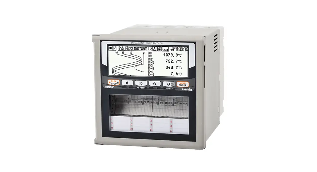
TCD210149AD KRN100 Series 100 mm Hybrid Recorder
Instruction Manual
TCD210149AD KRN100 Series 100 mm Hybrid Recorder
Thank you for choosing our Autonics product.
Read and understand the instruction manual and manual thoroughly before using the product.
For your safety, read and follow the below safety considerations before using.
For your safety, read and follow the considerations written in the instruction manual, other manuals and Autonics website.
Keep this instruction manual in a place where you can find easily.
The specifications, dimensions, etc. are subject to change without notice for product improvement. Some models may be discontinued without notice.
Follow Autonics website for the latest information.
Safety Considerations
- Observe all ‘Safety Considerations’ for safe and proper operation to avoid hazards.
 symbol indicates caution due to special circumstances in which hazards may occur.
![]() Warning Failure to follow instructions may result in serious injury or death.
Warning Failure to follow instructions may result in serious injury or death.
- Fail-safe device must be installed when using the unit with machinery that may cause serious injury or substantial economic loss. (e.g. nuclear power control, medical equipment, ships, vehicles, railways, aircraft, combustion apparatus, safety equipment, crime / disaster prevention devices, etc.)
Failure to follow this instruction may result in personal injury, economic loss or fire. - Do not connect, repair, or inspect the unit while connected to a power source. Failure to follow this instruction may result in fire or electric shock.
- Check ‘Connections’ before wiring. Failure to follow this instruction may result in fire.
- Do not touch the unit during or after operation for a while. Failure to follow this instruction may result in burn or electric shock due to high temperature of the surface.
- Do not use the unit in the place where flammable / explosive / corrosive gas, high humidity, direct sunlight, radiant heat, vibration, impact or salinity may be present.
Failure to follow this instruction may result in explosion or fire. - Install on the device panel, and ground to the F.G. terminal separately. When connecting the F.G. terminal, use AWG16 (1.25 mm²) or over. Failure to follow this instruction may result in fire or electric shock.
- Do not disassemble or modify the unit. Failure to follow this instruction may result in fire.
- Since Lithium battery is embedded in the product, do not disassemble or burn the unit. Failure to follow this instruction may result in fire.
![]() Caution Failure to follow instructions may result in injury or product damage.
Caution Failure to follow instructions may result in injury or product damage.
- Use the unit within the rated specifications. Failure to follow this instruction may result in fire or product damage.
- Use a dry cloth to clean the unit, and do not use water or organic solvent. Failure to follow this instruction may result in fire or electric shock.
- Keep the product away from metal chip, dust, and wire residue which flow into the unit. Failure to follow this instruction may result in fire or product damage.
- When connecting the power input or measurement input, use AWG20 (0.50 mm²) cable or over, and tighten the terminal screw with a tightening torque of 0.74 N·m to 0.90 N·m. Failure to follow this instruction may result in fire or malfunction due to contact failure.
- Do not use the load beyond rated switching capacity contact. Failure to follow this instruction may result in fire, relay broken, contact melt, insulation failure or contact failure.
- Use the transmitter output card only for the power for the transmitter. Failure to follow this instruction may result in output module damage.
- When connecting the temperature sensor (TC, RTD) or analogue input (voltage, current) as input to the universal input card, set the jumper pin to the correct place
for the connected input type.
If the jumper pin is placed improperly, it may result in product damage or malfunction.
Cautions during Use
- Follow instructions in ‘Cautions during Use’. Otherwise, it may cause unexpected accidents.
- Install a surge absorber at each end of inductive load coil when controlling high-capacity power relay or inductive load (e.g. magnet).
- Check the polarity of the terminals before wiring the temperature sensor. For RTD temperature sensor, wire it as 3-wire type, using cables in same thickness and length. For thermocouple (CT) temperature sensor, use the designated compensation wire for extending wire.
- Keep away from high voltage lines or power lines to prevent inductive noise. In case installing power line and input signal line closely, use line filter or varistor at power line and shielded wire at input signal line. Do not use near the equipment which generates strong magnetic force or high frequency noise.
- This unit may be used in the following environments.
– Indoors (in the environment condition rated in ‘Specifications’)
– Altitude max. 2,000 m
– Pollution degree 2
– Installation category II
Ordering Information
This is only for reference.
For selecting the specified model, follow the Autonics website.
KRN100 – ❶ ❷ ❸ ❹ – ❺ ❻ – 0 S
❶ Input channel
02: 2 CH (universal input card × 1)
04: 4 CH (universal input card × 2)
06: 6 CH (universal input card × 3)
08: 8 CH (universal input card × 4)
10: 10 CH (universal input card × 5)
12: 12 CH (universal input card × 6)
❷ Digital input
0: None
1: 6 (digital input card × 1)
2: 12 (digital input card × 2)
❸ Alarm transistor output
0: None
1: 6 (transistor alarm output card × 1)
2: 12 (transistor alarm output card × 2)
❹ Alarm relay output
0: None
1: 4 (relay alarm output card × 1)
2: 8 (relay alarm output card × 2)
3: 12 (relay alarm output card × 3)
❺ Transmitter power output
0: None
1: 3 (transmitter power output card × 1)
2: 6 (transmitter power output card × 2)
3: 9 (transmitter power output card × 3)
4: 12 (transmitter power output card × 4)
❻ Communication output
0: None
1: RS485 / Ethernet / USB
(communication output card × 1)
Manual
For proper use of the product, refer to the manuals and be sure to follow the safety considerations in the manuals.
Download the manuals from the Autonics website.
Software
Download the installation file and the manuals from the Autonics website.
■ DAQMaster
It is the comprehensive device management program for Autonics’ products, providing parameter setting, monitoring and data management.
Product Components
- Product
- Recording paper
- Instruction manual
- USB memory
- Ink cartridge
- Bracket × 2
- Basic connector × 2 (the no. of additional connectors depends on the input/output card.)
Sold Separately
- Universal input card: KRN-UI2
- Transistor alarm output card: KRN-AT6
- Transmitter power output card: KRN-24V3
- Digital input card: KRN-DI6
- Relay alarm output card: KRN-AR4
- Communication output card: KRN-COM
Specifications
| Series | KRN100 |
| LCD type _ | STN Graphic LCD |
| Resolution | 320 x 120 pixel |
| Brightness adjustment | 4-level (OFF / Min / Standard / Max) |
| Backlight | White LED, 2-level (Temp/Always) |
| No of input channel ‘ | 2 / 4 / 6 / 8 / 10 / 12 CH model (2 CH / universal input card) |
| Universal input | Please refer to ‘Input/Output’ for detailed information about universal input. |
| Sampling cycle’) | lto 4 CH:25 ms/125 ms/250 ms,5to12 CH:125 ms/250 ms (thermocouple (TC) – R, U, S, T: 50 ms) |
| Graph mode recording speed | 10, 20,40, 60, 120,240 mm / H |
| Recording accuracy 1 | ± 0.5 % F.S. |
| Saving cycle 1 | 1 to 3600 sec (inner log file is saved at 1 sec interval) |
| Internal memory 1 | 512 MB |
| External memory °2) 1 | USB memory max 32 GB |
| Recording paper | 113 mm x 9 m |
| Ink cartridge _ | Normal printing is available after going and returning printing maximum 5 times within 7 days after opening the unit |
| Ink dry time 1 | 15 minutes |
01) Internal sampling cycle is average movement filter and alarm output operation unit time.
02) USB memory is included in the box. If you use USB memory you purchased separately, it could not be recognized
| Power supply | 100-240 VAC∼ 50 / 60 Hz |
| Allowable voltage range | 85 to 110 % of rated power supply |
| Power consumption | ≤ 23 VA |
| Dielectric strength | Between power terminals and case: 2500 VAC∼ 50 / 60 Hz for 1 minute (except Ethernet and USB device) |
| Vibration (conveying and storing) | 10 to 60 Hz 4.9 m / s2 X, Y, Z in each X, Y, Z direction for 1 hour |
| Vibration (operating) | 10 to 60Hz 1 m / s2 X, Y, Z in each X, Y, Z direction for 10 minutes |
| Insulation resistance | ≥ 20 MΩ (500 VDC |
| Noise immunity | ± 2 kV square wave noise (pulse width 1 ㎲) by noise simulator |
| Time accuracy | Within ± 2 min / year (available up to 2100 year) |
| Protection structure | IP50 (front part, IEC standard) |
| Ambient temperature | 0 to 50 ℃, storage: -20 to 60 ℃ (without the ink cartridge, no freezing or condensation) |
| Ambient humidity | 35 to 85 %RH, storage: 35 to 85 %RH (no freezing or condensation) |
| Approval | |
| Unit weight (packaged) | Unit weight (packaged) ≈ 1.7 to 2.0 kg (≈ 2.4 to 2.7 kg) |
Input / Output
Connect or disconnect the input / output card when the product is turned off.
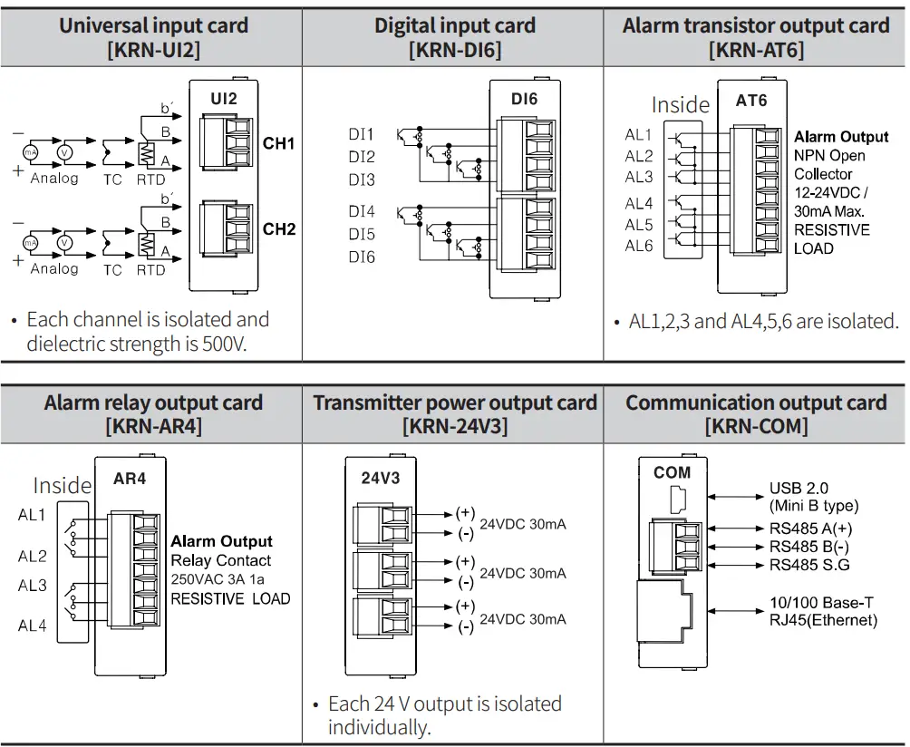
■ Universal input card (KRN-UI2)
• Input specifications
| RTD | J Pt100 0, DPt100 0, DPt50 0, Cul000, Cu50 0 (supplied current 420 μA) | |
| Thermocouple | B, C (W5), E, G, J, K, L, L (Russia), N, P, R, S, T, U | |
| Analog | Voltage | ± 60 mV, ± 200 mV, ± 2V, 1-5V, ± 5V, -1 V-10 V |
| Current | 0.00-20.00 mA, 4.00-20.00 mA | |
If sensor input line is longer, it is recommended to use shield cable to reduce noise.
• Input impedance
| RTD, thermocouple, voltage (mV) | ≥ 2 MΩ |
| Voltage (V) | ≥ 150 kΩ |
| Current | 51 Ω |
• Display accuracy
| Input type | Temperature | Display accuracy |
| RTD | Room temperature range (25 ℃ ± 5 ℃ | ± 0.1 % F.S. ± 1 digit (warm-up time: ≥ 30 minutes) • Cu50Ω (-200 ≤ T ≤ 200): ± 1.0 ℃ • DPt50Ω (-200 ≤ T ≤ 500): ± 1.5 ℃ |
| Out of room temperature range | ± 0.2 % F.S. ± 1 digit (warm-up time: ≥ 30 minutes) • 500 to 850 ℃ of all RTDs: ± 0.5 % of PV value ± 1 digit • Cu50Ω (-200 ≤ T ≤ 200): ± 2.0 ℃ • DPt50Ω (-200 ≤ T ≤ 500): ± 3.0 ℃ | |
| Thermocouple | Room temperature range (25 ℃ ± 5 ℃ | ± 0.1 % F.S. ± 1 digit (warm-up time: ≥ 30 minutes) • R, S, C, G (0 ≤ T ≤ 100): ± 4.0 ℃ • U, T (-200 ≤ T ≤ -100): ± 3.0 ℃ • U, T (-100 ≤ T ≤ 400): ± 2.0 ℃ • Below 400 ℃ of B: there is no accuracy standards. • Below -100 ℃ of all thermocouples: ± 0.3 % F.S. ± 1 digit |
| Out of room temperature range | ± 0.2 % F.S. ± 1 digit (warm-up time: ≥ 30 minutes) | |
| Analog | Room temperature range (25 ℃ ± 5 ℃) | ± 0.1 % F.S. ± 1 digit (warm-up time: ≥ 30 minutes) |
| Out of room temperature range | ± 0.2 % F.S. ± 1 digit (warm-up time: ≥ 30 minutes) |
• Resolution: 16 bit
■ Digital input card (KRN-DI6)
| Non-contact input | ON: residual voltage ≤ 1 VDCᜡ, OFF: leakage current ≤ 0.1 mA |
| Contact input | ON: ≤ 1 kΩ , OFF: ≥ 100 kΩ, short-circuit: ≈ 4 mA |
■ Alarm transistor output card (KRN-AT6)
NPN Open Collector, 12-24 VDC / ≤ 30 mA
■ Alarm relay output card (KRN-AR4)
| Capacity | 250 VACᜠ 3 A, 30 VDCᜡ 3 A, 1 Form A (resistive load) |
| Mechanical life cycle | ≥ 50,000,000 operations |
| Electrical life cycle | ≥ 100,000 operations (250 VACᜠ 3 A, 30 VDC |
■ Transmitter power output card (KRN-24V3)
24± 2 VDCᜡ, total 3 CH, per 1 CH ≤ 30 mA (built-in over current protection circuit)
■ Communication output card (KRN-COM)
| RS485 | Modbus RTU (It is recommended to use shielded cable over AWG 24.) |
| EEPROM life cycle | ≈ 1,000,000 operations (Erase / Write) |
| Ethernet | IEEE802.3(U), 10 / 100 BASE-T (Modbus TCP) |
| USB Device | USB V2.0 Full Speed (Device Control) |
RS422 / 485 and Ethernet communication outputs cannot be used at the same time.
The front USB Device port is only for data backup and rear USB device port is only for parameter setting.
Input / Output Card
Input Type Setting
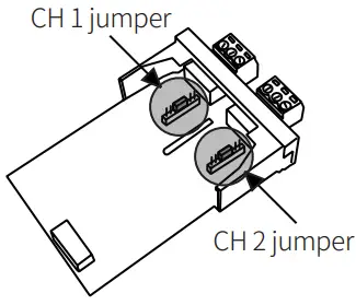
In the universal input card, place of jumper pin is different by input type.
Before setting the parameters, set the jumper pin channel 1 / 2 of universal input card (KRN-UI2) depending on input specification as below figure.
| Jumper pin setting | Input specification | Input disconnection alarm |
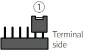 | 0 to 20 mA, 4 to 20 mA | 4 to 20 mA |
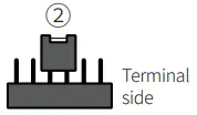 | TC, RTD, ± 60 mV, ± 200 mV | ○ |
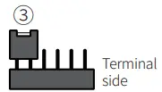 | ± 2 V, 1 to 5 V, ± 5 V, -1 to 10 V | × |
Connections
Based on the back of KRN100-04000-00-0S
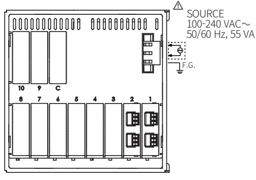
| Slot | Description |
| 1 to 6 | For universal input card |
| 7 to 10 | For digital input card, alarm output card, transmitter power output card |
| C | For communication output card |
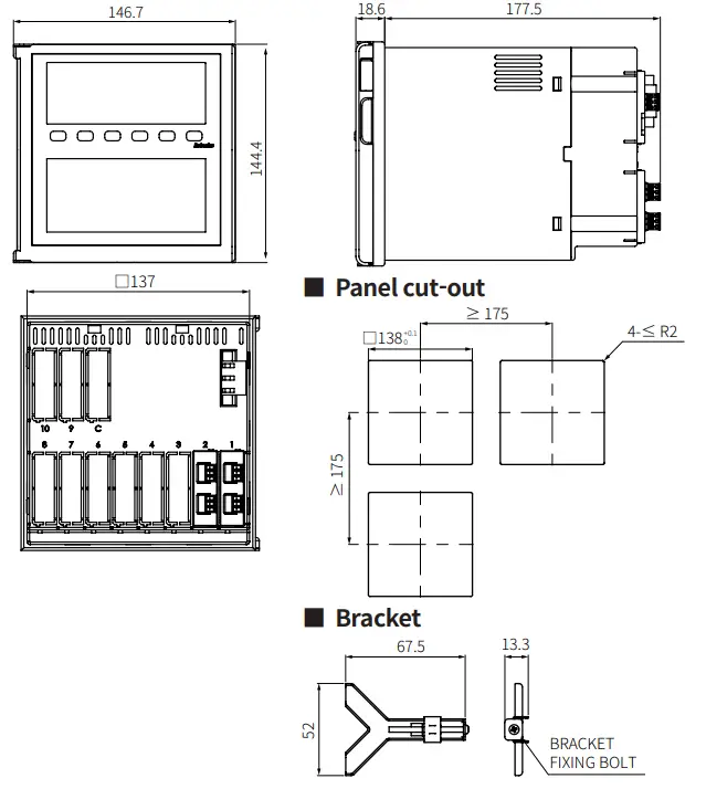
Dimensions
• Unit: mm, For the detailed drawings, follow the Autonics website.
Mode Setting
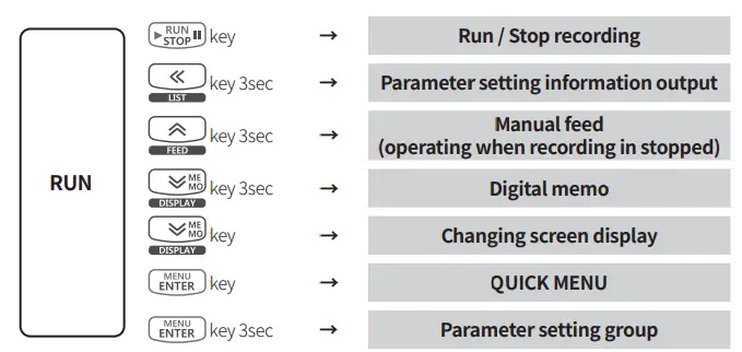
![]()
18, Bansong-ro 513Beon-gil, Haeundae-gu, Busan, Republic of Korea, 48002
www.autonics.com | +82-2-2048-1577 | [email protected]


