
MrTech CF1 Facial Recognition Access Control

Introduction
The product is a new generation of multi-function facial recognition Standalone Access Controller and Reader, which utilizes the new powerful, stable and reliable ARM core 32-bit microprocessor design. It can be used as a weigand reader, or as a Standalone Access Controller/Reader, And is suitable for access control applications in offices, residential communities, villa, banks and prisons.
FEATURE
| Feature | Specification |
| Card Type | 125KHz EM card(Optional) |
| 13.56MHz Mifare card (Optional) | |
| Keypad Characteristic | Infrared remote controller operation. |
| Output Protocol | Can operate as a reader. The transmission format could be adjusted by users. |
| Access Mode | card, facial recognition , fingerprint, card + fingerprint, card + facial recognition |
| Admin Card | admin card, admin fingerprint (add/delete) |
| User Capacity | 10,000 card users,1000 facial users and 600 fingerprint users |
| Facial Recognition Distance | 50cm-1m |
Technical Specifications
| Operating Voltage: DC12V | Standby Current: s180mA |
| Operating Current: S300mA | Operating Temperature: -40 ~ 60°( |
| Operating Humidity: 0 ~ 95% | Access mode: Fingerprint, card, facial recognition or multiple combination |
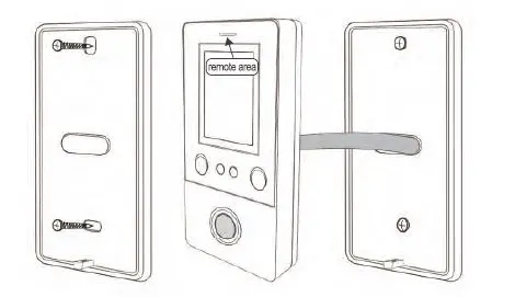
INSTALLATION
- Remove the back cover from the keypad using the supplied special screw driver
- Drill 2 holes on the wall for the self-tapping screws and dig a hole for the cable
- Put the supplied rubber bungs into the two holes
- Fix the back cover firmly on the wall with 2 self tapping screws
- Thread the cable through the cable hole
- Attach the keypad to the back cover. (See the figure below)
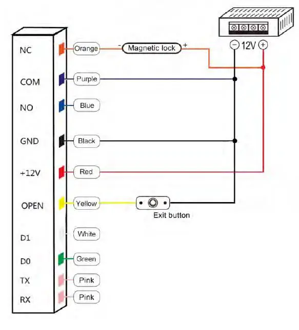
WIRING
| No. | Color | Marks | Description |
| Orange | NC | Relay NC | |
| 2 | Purple | COM | Relay COM |
| 4 | Blue | NO | Relay NO |
| 6 | Black | GND | Negative power supply end |
| 7 | Red | +12V | Positive power supply or AC power supply end |
| 8 | Yellow | OPEN | Exit button input end |
| 9 | White | D1 | Wiegand input (only when used as a reader) |
| 10 | Green | DO | W iegand input (only when used as a reader) |
iagram
Common Power Supply
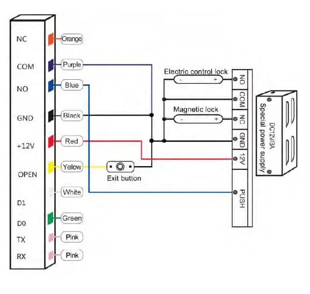
Special Power Supply
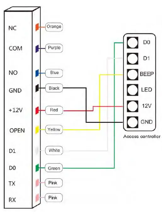
Reader Mode
Sound and Light Indication
| Operation Status | Light indicator | Buzzer |
| Stand by | Red | |
| Operation successful | Green | Beep- |
| Operation failed | Beep-Beep-Beep | |
| Admin card enter programming | Beep– | |
| Admin card exit programming | Beep- | |
| Press digital key | Beep | |
| Press* key | Beep– | |
| Read card under card+fingerprint mode | Red indicator flash slowly | Beep- |
| Read card under card+facial mode | Red indicator flash slowly | Beep– |
| Read multi user cards | Red indicator flash slowly | Beep- |
| Enter programming mode | Red indicator flash slowly | |
| Enter setting status | Orange | |
| Unlocking | Green | |
| Buzzer alarm | Red indicator flash quickly | Alarm |
Standalone Mode Settings
Device Management
Common Operation
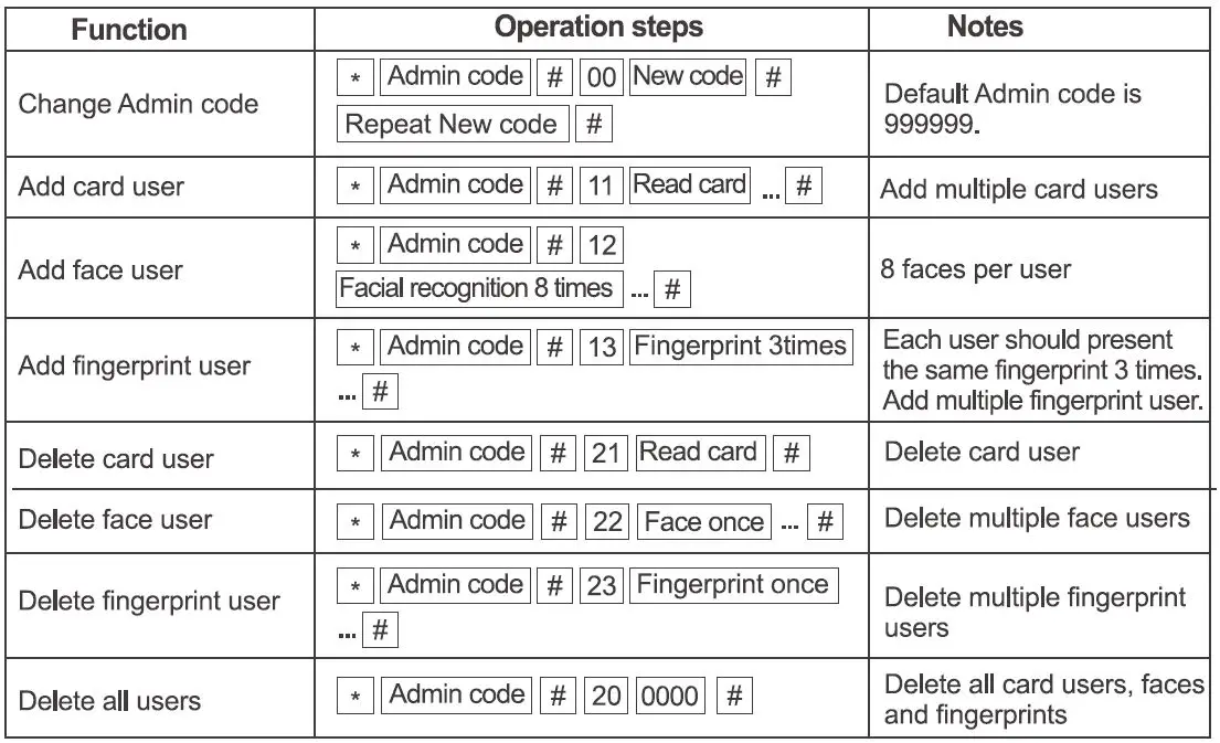
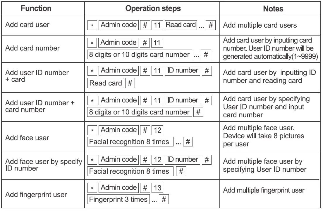
Add Users
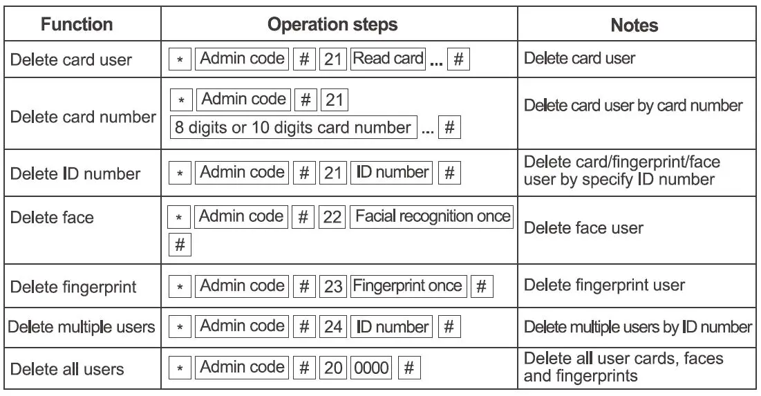
Delete Users
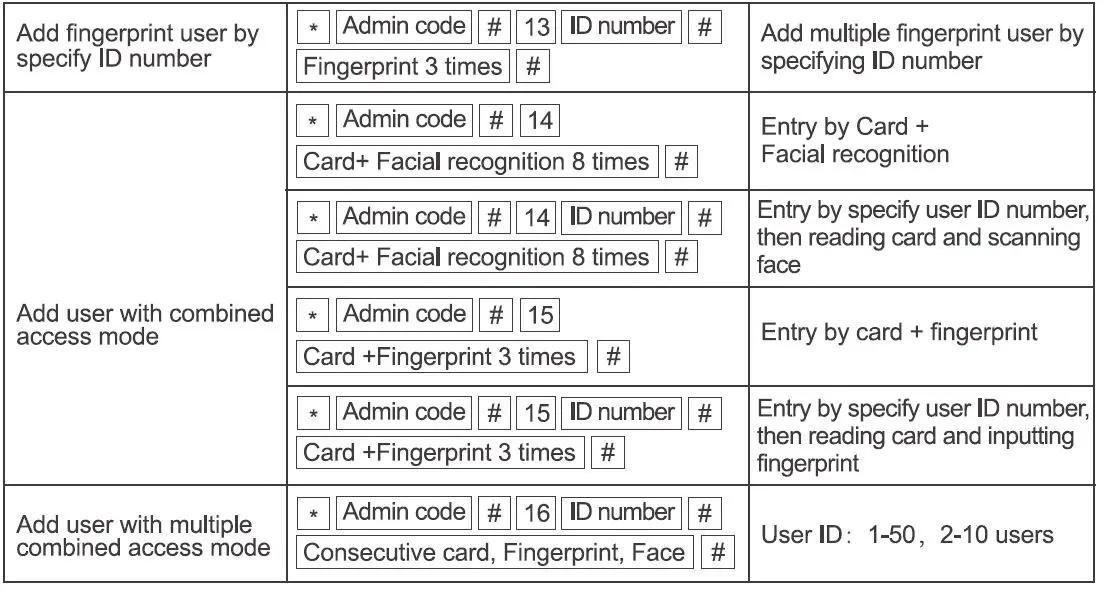
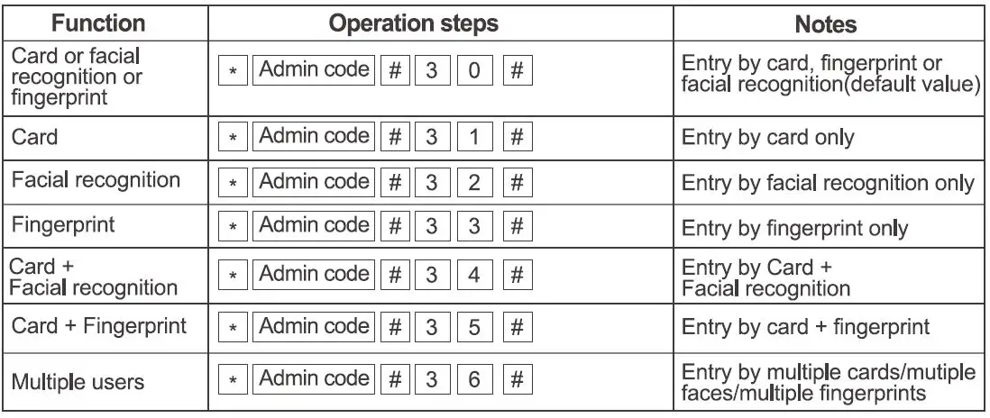
Access ways
Advanced Settings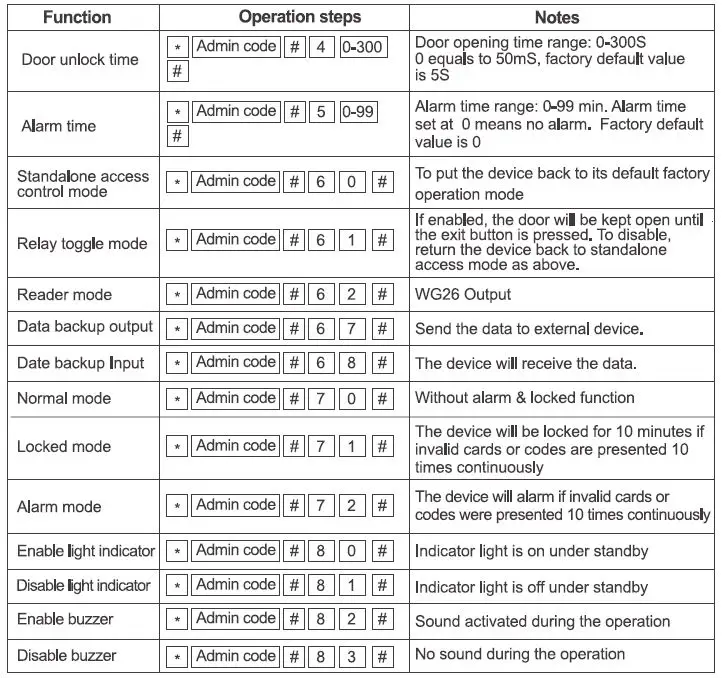
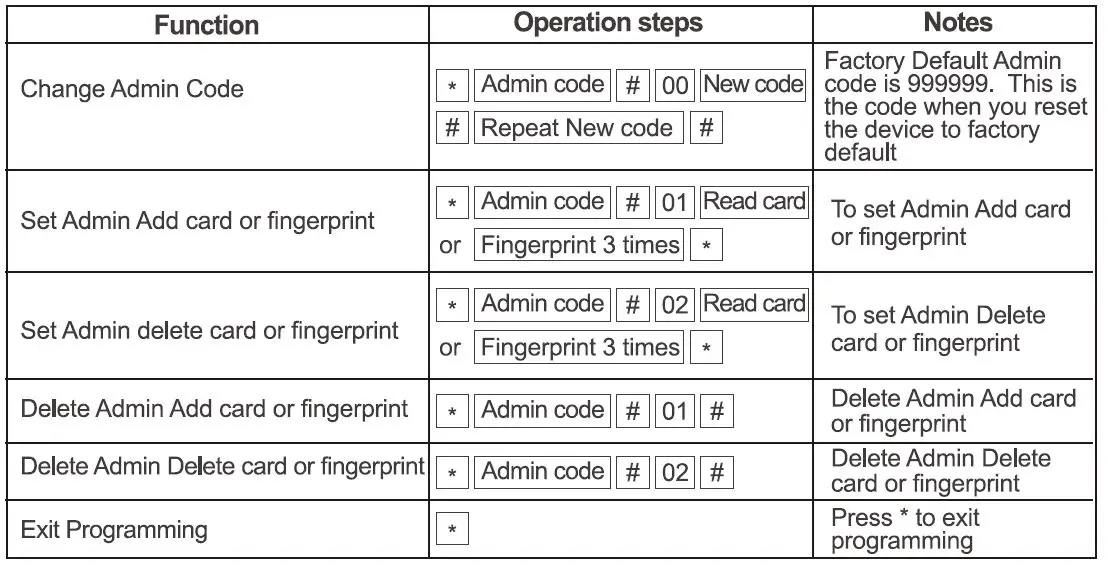
Admin Card Operation
Add Card
Read admin add card Read the 1st user card Read the 2d user card Read admin add card
Note: The Admin Add card is used to add card users continuously and quickly. When you present the Admin Add card. you will hear short BEEP SOunds twice and the indicator light turns orange. You have entered into Add user programming mode. You can present the cards for programming now.After all the cards are added, present the Admin Add card again. You will hear long BEEP” sound once and the indicator light turns red, indicating that you have exited the Add card user programming mode.
Delete Card
Read admin delete card Read the 1st user card Read the 2d user card Read admin delete card
Note: The Admin Delete card is used to delete card users continuously and quickly. When you present the Admin Delete card.you will hear short “BEEP” sounds twice and the indicator light turns orange. You have entered into Delete user programming mode. You can now present the cards for deletion.VWhen it is completed, you can present the Admin Delete card and you will hear a long “BEEP” sound once and the indicator light turns red,indicating that you have exited the Delete card user programming mode.
User Operation
Acknowledging the Alarm
Read admin card or Read valid user card or Input valid fingerprint or Press Admin code #
Note: When the alarm is activated, users can acknowledge and stop the alarm by reading valid user or Inputing valid fingerprint or pressing admin code.
Reset to Factory Default
Users can reset to device to its factory default if the Admin code is forgotten or the user wants to place the device back to factory original settings. To reset, follow the procedures below: Power off the device. Hold down the Exit button. Power on. Release the Exit button only when you hear the beep sound twice. The Admin code has been reset to 999999, factory and the device has defaulted to factory seting
Note: Note: Registered user data won’t be deleted when reset to factory default.
Data Backup Operation
Example: Backup the data of machine A to machine B The pink wire of machine A connects the pink-white wire of machine B, the pink-white wire of machine A connects the pink wire of machine B, set B for receiving mode at first, then set A for sending mode, the indicator light turns green flash during the data backup, data backup is successful when indicator light turns red.


