Shenzhen Hobk Electronic Technology HBK-D01 RFID Card Reader User Manual
Warm Tips
- Confirm the voltage (12VDC) and differentiate positive anode and cathode of the power supply.
- About the wiring between the reader and the controller, the wire should be 22 AWG at least and the length should not exceed 100 meters.
- When external power is used, suggest to use same power GND with controller panel. It is recommended to use multi-strand twisted pair cable to connect card reader to access controller.
- There is no need to wire the LED and BEEP cables if you do not need the card reader to prompt an authorized card through sound and light.
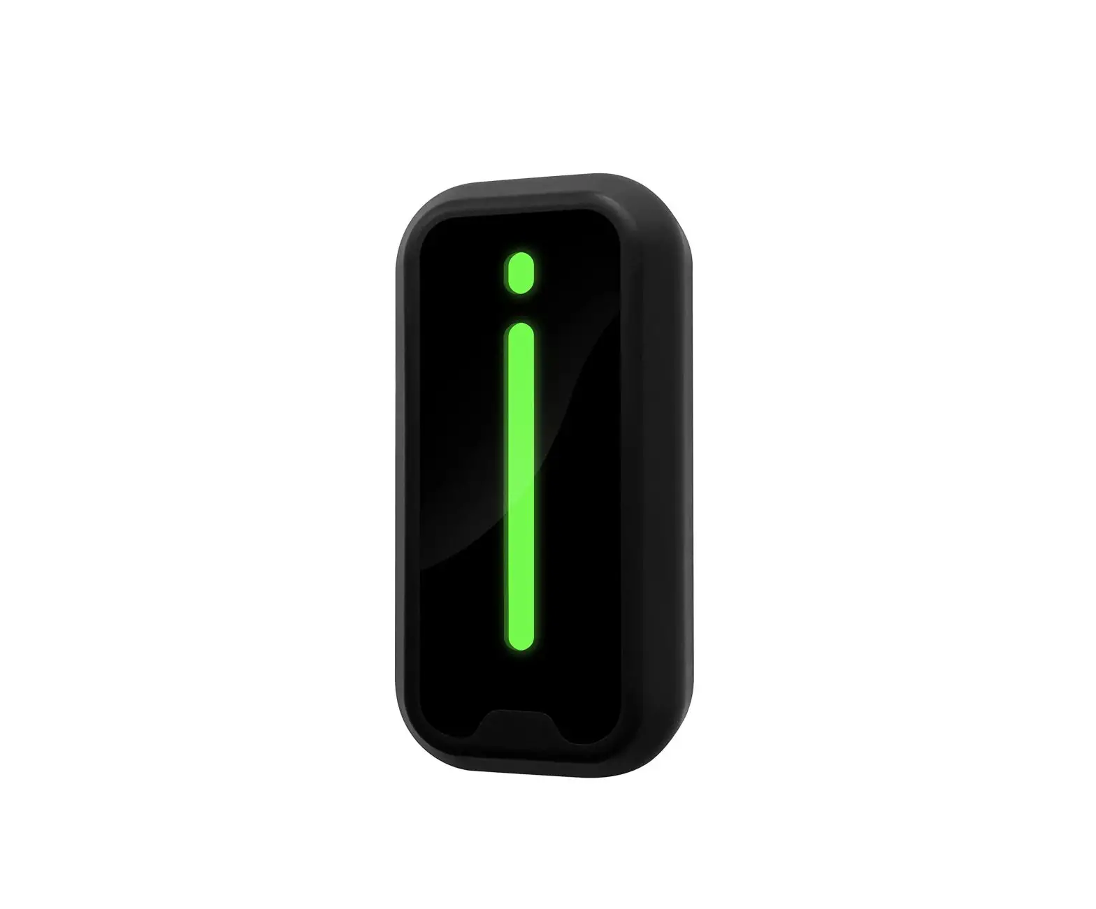
Introduction
The RFID card reader can’t work-alone and it needs to work with Wiegand protocol access controller, such as access control panel, fingerprint device or master controller.
It uses ST MCU to ensure stable performance, and low-power circuit makes the service life longer.
Features
- The maximum reading distance is 6cm.
- Waterproof, conforms to IP66.
- It is useful for safety door system, easy to connect and use.
- Ultra-low power consumption, the standby current is less than 50mA.
- Support wiegand 26bits or wiegand 34bits output format.
- Fast response speed, the door opening time is less than 0.3s.
- Widely used in factories, houses, residential quarters, offices, mechanical and electrical control equipment and so on.
Specification
| Working Voltage | 12VDC | Static Current | ≤50mA |
| Card Type | EM-ID | Frequency | 125KHz |
| Working Temperature | -40℃~60℃ | Working Humidity | 10%-90%RH |
| Panel Material | PC | Waterproof Rating | IP66 |
| Shell Material | PC + ABS | Shell Size | 90x45x19mm |
| Output Format (Selectable) | Wiegand 26bits Wiegand 34bits | Communication Distance | <100M |
| Status Indication | Bi-color LED + Buzzer | Lead Cable Length | 25cm |
| LED Status Indication | Red means standby, Green means activated/triggered | ||
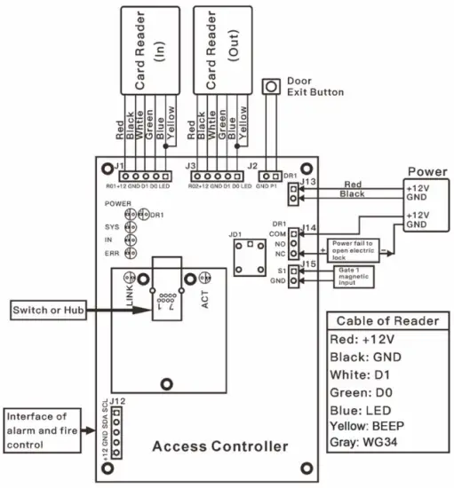
Wiring Definition
| Color | Functionality | Description |
| Red | +12V | +12V power input |
| Black | GND | GND |
| Green | D0 | Wiegand output D0 |
| White | D1 | Wiegand output D1 |
| Blue | LED | LED signal feedback |
| Yellow | BEEP | Buzzer signal feedback |
| Gray | Wiegand 34bits | Optional |
Note:
If the output format of the card reader you want is Wiegand 34bits, please connect the Gray wire and the Black wire together.
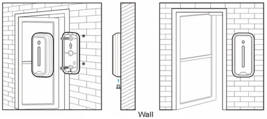
Installation
- Remove the back cover from the reader
- Drill 2 holes on the wall for the self-tapping screws and 1 hole for the cable
- Put the supplied rubber plugs into the 2 holes
- Fix the back cover firmly on the wall with 2 self-tapping screws
- Thread the cable through the cable hole
- Attach the keypad to the back cover

Sound and Light Indication
| Operation Status | LED Indicator | Buzzer |
| Standby | Red | |
| Read authorized card | Green | A short beep |
| Read un-authorized card | Flash red 3 times | 3 short beeps |
Remarks: The card reader will prompt sound and light indication only when the LED and BEEP cables are connected to the access controller.
Wiring Diagram
Packing List
| Name | Quantity | Remarks |
| Card Reader | 1 | |
| User Manual | 1 | |
| Plastic Anchors | 2 | Used for fixing |
| Self-Tapping Screw | 2 | #7×1”, used for fixing |
FCC Statement
Changes or modifications not expressly approved by the party responsible for compliance could void the user’s authority to operate the equipment.
This equipment has been tested and found to comply with the limits for a Class B digital device, pursuant to Part 15 of the FCC Rules. These limits are designed to provide reasonable protection against harmful interference in a residential installation. This equipment generates uses and can radiate radio frequency energy and, if not installed and used in accordance with the instructions, may cause harmful interference to radio communications. However, there is no guarantee that interference will not occur in a particular installation. If this equipment does cause harmful interference to radio or television reception, which can be determined by turning the equipment off and on, the user is encouraged to try to correct the interference by one or more of the following measures:
- Reorient or relocate the receiving antenna.
- Increase the separation between the equipment and receiver.
Connect the equipment into an outlet on a circuit different from that to which the receiver is connected. - Consult the dealer or an experienced radio/TV technician for help
This device complies with part 15 of the FCC rules. Operation is subject to the following two conditions:
- this device may not cause harmful interference, and
- this device must accept any interference received, including interference that may cause undesired operation.
This equipment complies with FCC radiation exposure limits set forth for an uncontrolled environment.


