
ELKOep RFWB-20/G Wireless Switch Socket
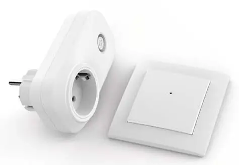
Combination of iNELS wall-mounted wireless controller and switch socket.
Content
On-wall button controller PLASTIC – 2 buttons RFWB-20/G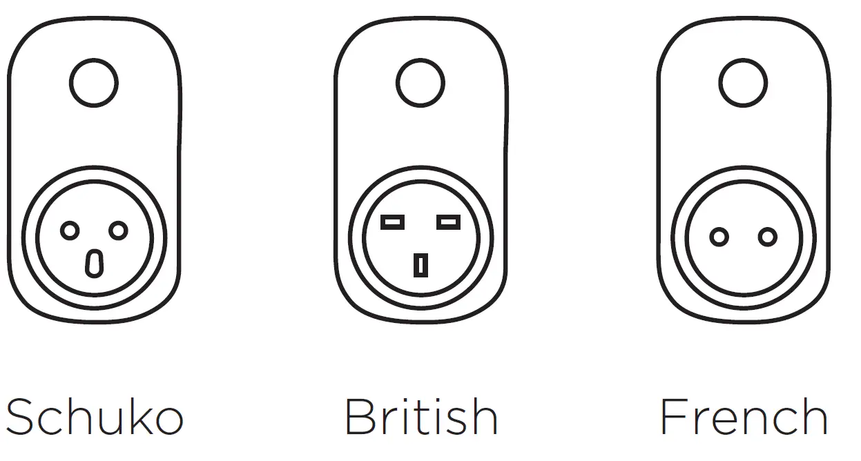
Switching socket-plug RFSC-61N
EAN 8595788183215 (On-wall button controller PLASTIC – 2 buttons + Switching socket-plug “French“)
EAN 8595788183314 (On-wall button controller PLASTIC – 2 buttons + Switching socket-plug “British“)
EAN 8595788183413 (On-wall button controller PLASTIC – 2 buttons + Switching socket-plug “Schuko“)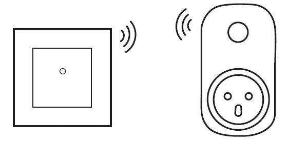 The individual elements in the iNELS set are paired and their functions are preset.
iNELS Wireless switch socket enables the basic function of controlling electrical appliances – ON / OFF.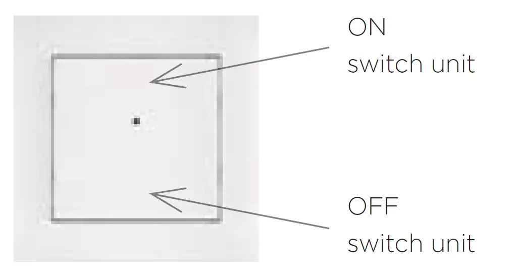 The settings of the wall controllers can be changed – see detailed manuals of iNELS elements.
Characteristics
- The wireless controller is used to control switches and dimmers (lights, gate, garage door, blinds, etc.).
- RFWB-20/G: two buttons enable control one or two units independently (depending on the type of switching element).
- The fl at design with level base makes it ideal for fast installation on any surface (fi xation with adhesive or screws in the installation box).
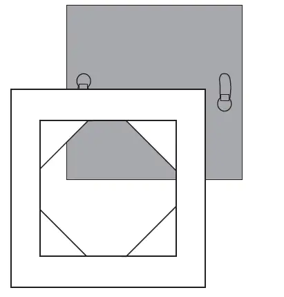
Replacement of a battery RFWB-20
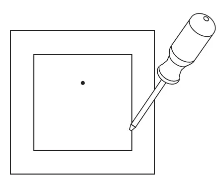
- Using a screwdriver, carefully pry off the device from the frame.

- Gently pull to remove the cover.

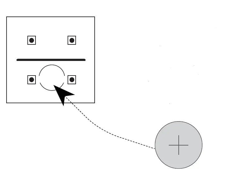
- Slide the CR2032 battery into the battery holder. Observe the polarity.

- Snap on the cover. The LED opening must be located in the upper part (for the RFWB-40, observe the positioning of the left and right cover

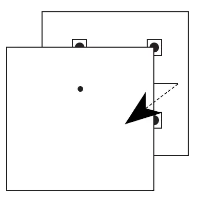
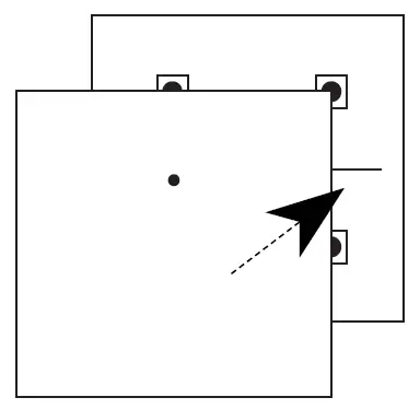
- Place the frame on the rear part.

- Snap the device with the cover into the prepared frame.

Safe handling
When handling a device unboxed it is important to avoid contact with liquids. Never place the device on the conductive pads or objects, avoid unnecessary contact with the components of the device.
Technical parametres
Technical parametres RFWB-20/G
| Supply voltage: | 3 V battery CR 2032 |
| Transmission indication: | red LED |
| Number of buttons: | 2 |
| Transmitter frequency: | 868.5 MHz |
| Signal transmission method: | unidirectionally addressed message |
| Range in free space: | up to 200 m |
| Other data | |
| Operating temperature: | -10 … +50 °C (14 … 122 °F) |
| Operating position: | any |
| Mounting: | glue, screws |
| Protection: | IP20 |
| Contamination degree: | 2 |
| Dimensions: | |
| LOGUS90 frame – plastic: | 85 x 85 x 16 mm (3.3“ x 3.3“ x 0.6“) |
| LOGUS90 frame – metal, glass, wood, granite: |
94 x 94 x 16 mm (3.7“ x 3.7“ x 0.6“) |
| Weight: | 38g * (1.3 oz) |
| Related standards: | EN 60669, EN 300220, EN 301489 |
* Comes with plastic frame.
Attention:
When you instal iNELS RF Control system, you have to keep minimal distance 1 cm between each units. Between the individual commands must be an interval of at least 1s.
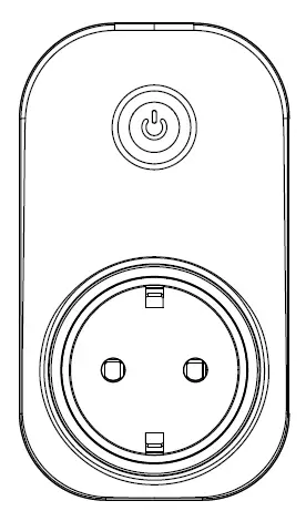
Switching socket-plug RFSC-61N (Schuko, French, British)
Characteristics
- The switched socket with 1 output channel is used to control fans, lamps, heaters and appliances, which are connected by a power cord.
- They can be combined with detectors, controllers, iNELS RF Control system components.
- Thanks to the socket design, installation is simple by direct insertion into the existing socket.
- It enables connection of the switched load up to 16A (4.000 W).
- Multi-function design – button, impulse relay and time function of delayed ON or OFF with time setting of 2 s – 60 min.
- The switched socket may be controlled by up to 32 channels (1 channel represents 1 button on the controller).
- The programming button on the socket is also used for manual control of the output.
- Memory status can be pre-set in the event of a power failure.
- Range up to 200 m (in open space), if the signal is insuffi cient between the controller and unit, use the signal repeater RFRP-20 or protocol component RFIO2 that support this feature.
- Communication frequency with bidirectional protocol iNELS RF Control2 (RFIO2).
- Produced in 3 designs of sockets and plugs.
Assembly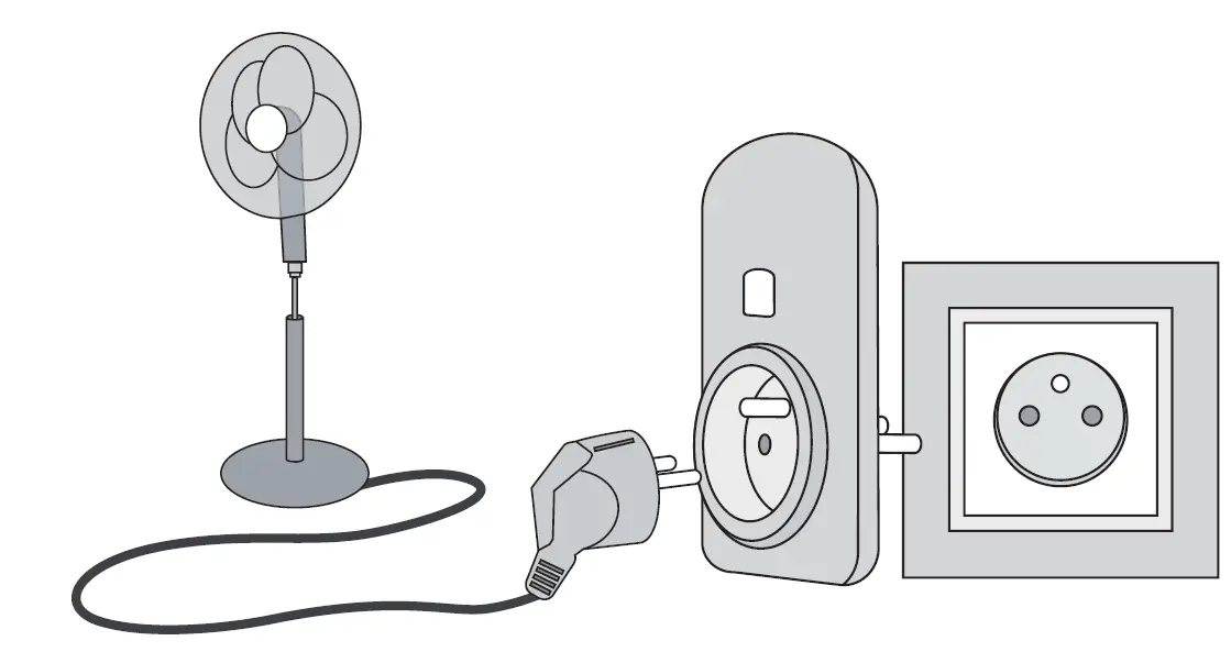
Technical parameters RFSC-61 N/230V
| Supply voltage: | 230 V / 50-60Hz |
| Apparent power: | 7 VA |
| Dissipated power: | 0.7 W |
| Supply voltage tolerance: | +10 %; -15 % |
| Output: | |
| Number of contacts: | 1x switching (AgSnO2) |
| Rated current: | 16 A / AC1 |
| Switching power: | 4000 VA / AC1, 384 W / DC |
| Peak current: | 30 A / < 3 s |
| Switching voltage: | 250 V AC1 / 24 V DC |
| Min. switching power DC: | 500 mW |
| Mechanical service life: | 3×10⁷ |
| Electrical service life (AC1): | 0.7×10⁵ |
| Control: | |
| Manual control: | button PROG (ON/OFF) |
| Other data: | |
| Operating temperature: | -15 … + 50 °C (5 … +122 °F) |
| Working position: | any |
| Protection: | IP30 |
| Overvoltage category: | III. |
| Contamination degree: | 2 |
| Dimensions: | 63 x 110 x 74 mm |
| Weight: | 129 g |
| Related standards: | EN 60730, EN 63044, EN 300 220, EN 301 489 |
Compatibility
 The device can be combined with all system components, controls and devices of iNELS RF Control and iNELS RF Control2.
The detector can be assigned an iNELS RF Control2 (RFIO2) communication protocol.
Radiofrequency signal penetration through various construction materials
Range up to 200 m (2 inch) in open space,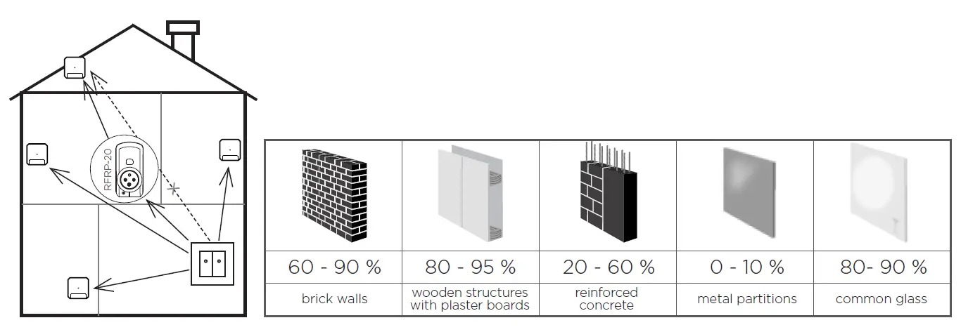
Warning
Instruction manual is designated for mounting and also for the usage of the device. It is always a part of its packing. Installation and connection can be carried out only by a person with adequate professional qualifi cation with understanding this instruction manual and functions of the device, and while observing all valid regulations. Trouble-free function of the device also depends on transportation, storing and handling. In case you notice any sign of damage, deformation, malfunction or missing part, do not install this device and return it to its seller. It is necessary to treat this product and its parts as electronic waste after its lifetime is terminated. Before starting installation, make sure that all wires, connected parts or terminals are de-energized. While mounting and servicing observe safety regulations, norms, directives and professional, and export regulations for working with electrical devices. Do not touch parts of the device that are energized – life threat. Due to transmissivity of RF signal, observe correct location of RF components in a building where the installation is taking place. RF Control is designated only for mounting in interiors. Devices are not designated for installation into exteriors and humid spaces. The must not be installed into metal switchboards and into plastic switchboards with metal door – transmissivity of RF signal is then impossible. RF Control is not recommended for pulleys etc. – radio-frequency signal can be shielded by an obstruction, interfered, battery of the transceiver can get fl at etc. and thus disable remote control.
Designed & Manufactured by:
ELKO EP, s.r.o. Palackého 493, 769 01 Holešov, Všetuly,
Czech republic, www.elkoep.com, Hotline: +420 800 100 671


