![]() APS 2 Channel Pendulum Control
APS 2 Channel Pendulum Control
User Manual
Introduction
Dear customer, we strongly recommend that you read these manuals and the warning notes thoroughly before installing and operating your device. The device is not a toy (15+).
NOTE: Make sure that the outputs are set to appropriate value before hooking up any other device. We can’t be responsible For any damage if this is disregarded.
General information
We recommend studying this manual thoroughly before installing and operating your new device. Place the decoder in a protected location. The unit must not be exposed to moisture.
NOTE: Some functions are only available with the latest firmware. Please make sure that your device is programmed with the latest firmware.
Summary of Funktions
- DC/AC/DCC operation
- Digital controllable via decoder (DCC, MM)
- 5 Amps pendula output
- Current- and temperature control
- 3 contact inputs
- Middle stop function available
- Poti for stop time
- Poti for drive time
- Poti for drive speed
- Screw drives for stable mounting
- State LED
- Drive time between 1 – endless sec.
- Wait time between 2 sec to 4 min.
- Slew times configurable with our PC programmer
- All trains can be pendula control also with decoders
- Fits to LGB bumper
Scope of supply
Manual mien APA
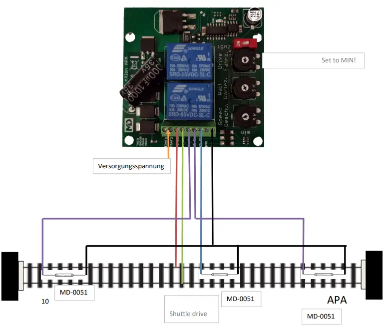
Hook-Up
Install your device in compliance with the connecting diagrams in this manual. The device is protected against shorts and excessive loads. However, in case of a connection error e.g. a short this safety feature can’t work and the device will be destroyed subsequently.
Make sure that there is no short circuit caused by the mounting screws or metal.
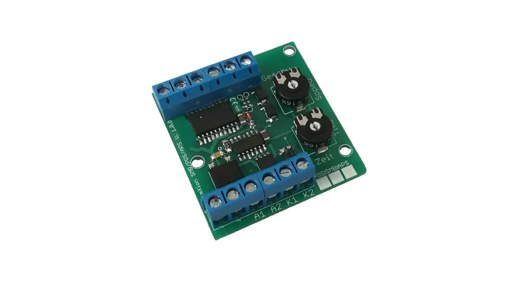
Connectors
Speed: 1-255 steps (255 = max. voltage)
Wait time: 2 sek – 4 min.
Drive time: 1 – 127 sec. If 0 (min) then endless if contact is pressed Middle stop is by 50% if activated.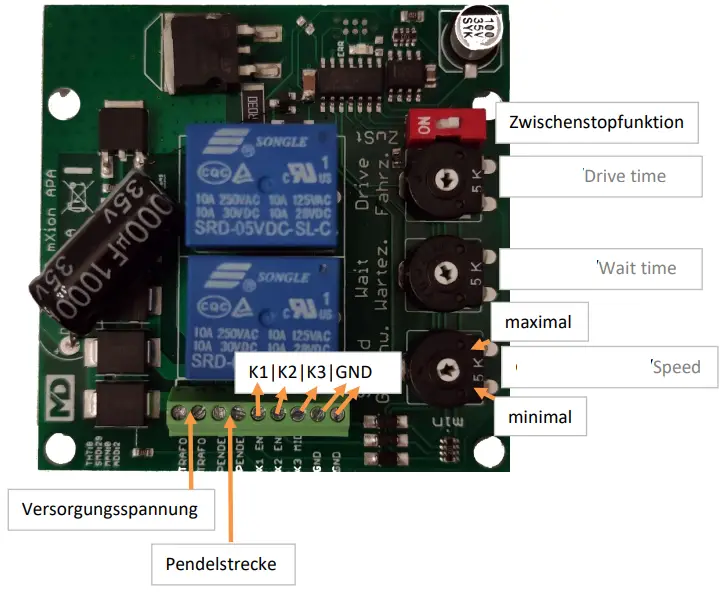
Pendula control via time
The driving and stopping times as well as the speed is about the right sides controller set (POTI). Alternatively, a red switch to be activated on an intermediate stop half way.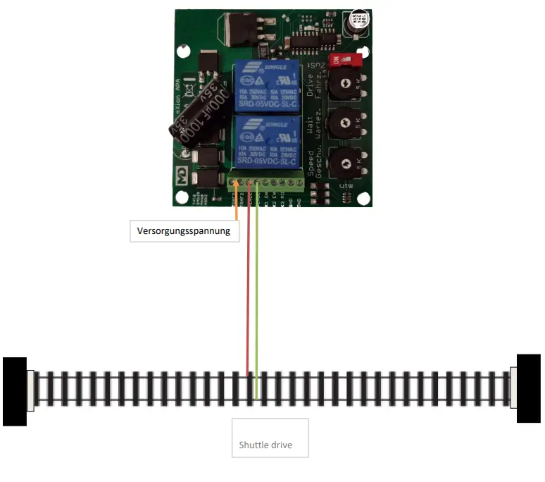
Pendula control via contact
 Pendula control via digital
When connecting a digital voltage to the APA there is the possibility of the delay times set for slow starting and braking. There is also the possibility of using the turnout command switching the control on and off and with it that interrupt or start commuting. Of it is also possible when using our 30Z digital center with model railroad time a small one activate automation. You can do this at certain modest rain times (e.g. 9 am and 12 o’clock off) activate the control. Of the model railway factor can be set at our 30Z.
The further connection corresponds to the previous pictures. In the appendix you will find the CV list for configuration.
The module can handle DCC an Motorola
Product description
Further is it possible in digital to use a time control to create a schedule. To do this, our digital command station 30Z is needed.
In digital, the LED is activate when deactivated pendulum control. If the LED flashes it is on short circuit before. To do this, the APA must be de-energized be asked.
S = Default, L = Loco address, S = Switch address, LS = Loco and switch address usable
| CV | Description | S | L/S | Range | Note |
| 7 | Software version | – | – | read only (10 = 1.1) | |
| 7 | Decoder reset functions | ||||
| 2 ranges available | 11 16 | basic settings programming lock (CV 15/16) | |||
| 8 | Manufacturer ID | 160 | – | read only | |
| 7+8 | Register programming mode | ||||
| Reg8 = CV-Address Reg7 = CV-Value | CV 7/8 don’t changes his real value CV 8 write first with cv-number, then CV 7 write with value or read (e.g.: CV 49 should have 3) CV 8 = 49, CV 7 = 3 writing | ||||
| 15 | Programming lock (key) | 95 | S | 0 – 255 | to lock only change this value |
| 16 | Programming lock (lock) | 95 | S | 0 – 255 | changes in CV 16 will change CV 15 |
| 18 | Switch address calculation | 0 | S | 0/1 | 0 = Switch address like norm 1 = Switch address like Rocco, Fleischmann |
| 20 | Switching address high | 0 | W | 1 – 2048 | Switching address for switching the shuttle mode on / off |
| 21 | Switching address low | 1 | W | ||
| 22 | Pendulum control active at start | 1 | 0/1 | 0 = inactive, 1 = active | |
| 23 | Pendulum control status | 1 | 0/1 | do not change | |
| 24 | Start-up braking time | 15 | 1 – 255 | Time value 1 ms / value | |
| 25 | Switch-on time hour | 15 | 0 – 23 | For automatic operation when using model railway time with our 30Z | |
| 26 | Switch-on time minute | 0 | 0 – 59 | ||
| 27 | Switch-off time hour | 18 | 0 – 23 | ||
| 28 | Switch-off time minute | 0 | 0 – 59 | ||
| 29 | Time control activation | 0 | 0/1 | 0 = inactive, 1 = active | |
| 30 | Maximum current limit | 40 | 0 – 50 | Current limit in decamps (40 = 4A) | |
Technical data
Current: 20mA (without functions) Maximum function current: 5A
Temperature range: -20 up to 80°C
Dimensions L*B*H (cm): 6.4*6.4*4
micron-dynamics warrants this product against defects in materials and workmanship for one year from the original date of purchase. Other countries might have different legal warranty situations. Normal wear and tear, consumer modifications as well as improper use or installation are not covered.
Peripheral component damage is not covered by this warranty. Valid warrants claims will be serviced without charge within the warranty period. For warranty service please return the product to the manufacturer. Return shipping charges are not covered by micron-dynamics. Please include your proof of purchase with the returned good. Please check our website for up to date brochures, product information, documentation and software updates. Software updates you can do with our updater or you can send us the product, we update for you free.
Errors and changes excepted.
EC declaration of conformity
This product meets the requirements of the following EC directives and bears the CE mark for this.
2014/30/EU on electromagnetic compatibility. Underlying standards: EN 55014-1 and EN 61000-6-3. To the electromagnetic compatibility during operation to maintain, follow the instructions in this guide.
EN IEC 63000:2018 to limit the use of certain hazardous substances in electrical and electronic equipment (RoHS).
This product meets the requirements of EU Directive 2012/19/EC on electrical and waste electronic equipment (WEEE). Dispose of this product does not have the (unsorted) household waste, but run it the recycling to.
WEEE: DE69511269
Hotline
For technical support and schematics for application examples contact: micron-dynamics [email protected] [email protected]


