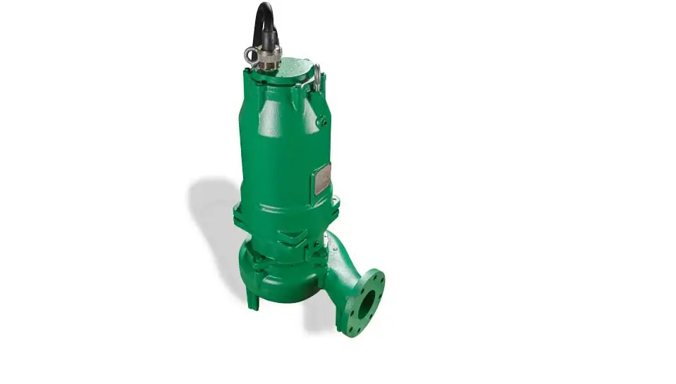

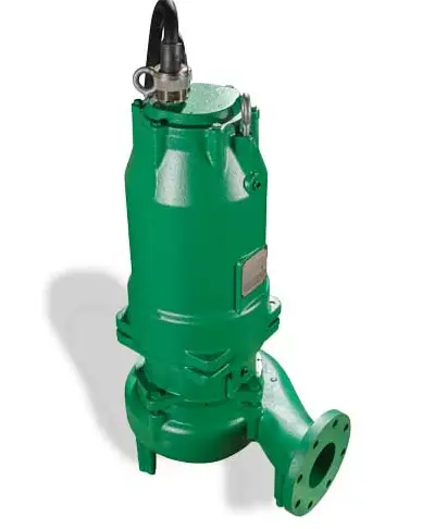
PENTAIR C4S(X* )P Submersible Solids Handling Pump
SAFETY INFORMATION
SAFETY SYMBOLS
This is the safety alert symbol. When you see this symbol on your pump or in this manual, look for one of the following signal words and be alert to the potential for personal injury:
DANGER warns about hazards that will cause serious personal injury, death or major property damage if ignored. warns about hazards that can cause serious personal injury, death or major property damage if ignored. warns about hazards that will or can cause minor personal injury or property damage if ignored.
The word NOTICE: indicates special instructions that are important but not related to hazards.
CALIFORNIA PROPOSITION 65 WARNING
This product and related accessories contain chemicals known to the State of California to cause cancer, birth defects or other reproductive harm.
GENERAL SAFETY
- Do not touch an operating motor. Modern motors can operate at high temperatures. To avoid burns when servicing pump, allow it to cool for 30 minutes after shutdown before handling.
- Follow all applicable local and state codes and regulations.
- Submersible pumps are not approved for and should not be used in swimming pools, recreational water installations, decorative fountains or any installation where human contact with the pump fluid is common. Pump is designed for municipal and commercial wastewater applications.
- Keep safety labels in good condition, replacing any missing or damaged labels.
- DO NOT run the pump dry. Dry running can overheat the pump, (causing burns to anyone handling it) and will void the warranty.
- The pump is permanently lubricated. No oiling or greasing is required in normal operation.
- Periodically inspect pump and system components.
- Wear safety glasses at all times when working on pumps.
- Keep work area clean, uncluttered and properly lighted. Store all unused tools and equipment.
- DO NOT use to pump flammable liquids.
- RISK OF FIRE OR EXPLOSION. Can cause severe personal injury, property damage or death. Do not smoke or use open flames in or around this system.
- CUTTING RISK. Risk of serious cutting or amputation exists. Use caution as liner plate is extremely sharp. Always keep fingers and hands away from cutting profiles. Disconnect all power sources prior to servicing pump. Pump may start without warning.
- RISK OF ASPHYXIATION. Installer(s) and/or service personnel must use proper Personal Protective Equipment and follow OSHA 29 CFR 1910.146 or OSHA 29 CFR 1926. Pump may be installed in a location classified as a confined space.
- BIOHAZARD RISK. Once wastewater source has been connected to system, Biohazard Risk exists. Installer(s) and/or service personnel must use proper personal Protective Equipment and follow handling procedures per OSHA 29 CFR 1910.1030 when handling equipment after wastewater source has been connected to system.
- NOTICE: FM rated models are only to be used in 60hz applications.
ELECTRICAL SAFETY
- Hazardous voltage. Can shock, burn, or kill. When installing, operating, or servicing this pump, follow the safety instructions listed below.
- ELECTROCUTION HAZARD: Must be installed by a qualified professional. Disconnect all electrical power before attempting service.
- DO NOT modify the cord. When wiring to a system control, connect ground lead to the system ground.
- DO NOT splice the electrical power cord.
- DO NOT allow the power leads on the end of the electrical cords to be submerged.
- DO NOT handle or service the pump while it is connected to the power supply.
- A water test must be taken before installation of any water treatment equipment. The water quality can significantly influence the life of your system. You should test for corrosive elements, acidity, total solids and other relevant contaminants, including chlorine and treat your water appropriately to ensure satisfactory performance and prevent premature failure.
GENERAL INFORMATION
This manual contains important safety information regarding the use of this product. This product should only be installed and serviced by a qualified professional. Carefully read and follow all safety instructions in this manual and on the unit itself before installing or operating pump. Keep this manual for future reference.
Reasonable care and safe methods should be practiced. Check local codes and requirements before installation.
UNPACKING PUMP
LIFTING HAZARD. Unassisted lifting of pump can cause injury. Mechanical assistance required.
DO NOT life pump by power cord.
When unpacking unit, check for damage. Claims for damage must be made at the receiving end through the delivery carrier. Damage cannot be processed from the factory.
RISK OF FIRE OR EXPLOSION. Before handling these pumps and controls, always disconnect the power first.
Do not smoke or use sparkable electrical devices or flames in a septic (gaseous) or possible septic sump. Do not pump flammable liquids with this pump.
PUMPS IN STORAGE OR NOT OPERATING
Pumps with silicon/carbide seals must have impellers manually rotated (6 revolutions) after setting non-operational for 3 months or longer and prior to electrical start-up.
Pumps with tungsten carbide seals must have impellers manually rotated (6 revolutions) after setting non-operational for 3 weeks or longer and prior to electrical start-up.
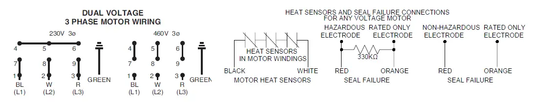
SEAL FAILURE PROBES HAZARDOUS DUTY RATED PUMPS:
All submersible pumps have two factory installed moisture detectors (seal failure probes). They should have a resistance of around 330K ohms for the series circuit in the seal chamber. Under normal operating conditions, the circuit remains around 330K ohm. If the circuit shows open the circuit is not complete indicating a broken wire, corroded wire, or loose connection.
If the lower seal leaks and moisture enters this chamber, the moisture would settle to the bottom of the chamber and will complete (significantly less than 330K ohms) the circuit between the moisture detectors.
NON-HAZARDOUS DUTY RATED PUMPS:
For all non-hazardous duty rated pumps the resistance(ohm) readings between the seal probe wires should be open in normal operating conditions. A lower resistance indicates water intrusion.
This circuit must be connected to a sensing unit and signaling device. This is supplied in a manufacturer built control panel. Failure to install such a device negates all warranties.
HEAT SENSORS
All motors in this family have heat sensors on or embedded in the motor winding to detect excessive heat. This prevents damage to the motor. If sensor trips due to excessive winding temperature, the starter in the panel breaks power to the pump.
Once the sensor resets, the starter is automatically reset for FM for continued operation of the pump. This circuitry is supplied in a Hydromatic control panel. The sensors are set to trip at 130°C. Failure to install such circuitry would negate FM approvals and all warranties by Hydromatic.
POWER CORDS
The power cord and heat sensor seal failure cord are potted into the cord cap. The cords must not be spliced.
Each cable has a green lead. This is the ground wire and must be grounded properly per NEC and/or local codes. Cords should be inspected for abnormal wear and replaced accordingly.
OVERLOAD HEATERS
If the Hydromatic electrical panel is not used, starters with 3 leg overload relay must be supplied on 3 phase pumps. Each leg is to have an identical heater sized in accordance with the nameplate amps on the motor housing. The amp draw on these submersible motors is slightly higher than a corresponding horsepower surface motor, so heaters must be sized by the nameplate rating.
Capacitor start single phase pumps have a run and start winding that draws different currents. To adequately protect these windings with the appropriate heaters, consult the factory.
The red lead is always the start winding of a pump using single phase.
INSTALLING SUMP LEVEL CONTROLS FLOAT CONTROLS
In either simplex, duplex or triplex systems, the lower or turn-off control is to be set to maintain a minimum level in the sump. This level shall be no more than 3-1/4″ from the top of the motor housing down to the surface of the sewage.
The second or turn-on control is set above the lower turn-off control. The exact distance between the two floats must be a compromise between a frequent pumping cycle (15 starts per hour max.) to control septicity, solids and a slower cycle for energy economy. This distance should be determined by the engineer or consulting engineer, depending on the conditions of the application.
PUMP INSTALLATION
INSTALLING PUMP IN SUMP
Before installing the pump in the sump, lay it on its side and rotate impeller. Impeller may be slightly stuck due to factory test water. The impeller should turn freely. DO NOT connect the power until after this test.
Clean all debris from sump and connect pump to piping. A check valve must be installed on each pump and a gate or plug valve
in each pump discharge is highly recommended. This valve should be installed on the discharge side of the check valve so
if it becomes necessary to service the check valve, the line pressure can be cut off. Single pump systems are sometimes installed without a check valve where it is desirable to self-drain the discharge line to prevent freezing. This can be done only with short discharge lines; otherwise water will return to the sump and cause short cycling of the pump.
MAKING ELECTRICAL CONNECTIONS
All electrical wiring must be in accordance with local codes, and only competent electricians should make the installations. Complete wiring diagrams are glued to the inside cover of the panel. It is VERY IMPORTANT to check all wires for grounds with an ohmmeter or Megger(r) after the connections are made as one grounded wire can cause considerable trouble.
IMPORTANT: If equipment is not properly wired and protected as recommended, the warranty is void.
The 230 volt 3 phase pump has a dual marked nameplate. For ordinary location pumps, voltage may be rewired by qualified personnel. For hazardous location pumps, voltage may be rewired by the manufacturer or a Class I, Div I equipment qualified electrician. Once the voltage is changed, the factory cord tag indicating 230 volt 3 phase must be removed.
For record keeping purposes, we suggest the pump be marked externally with the new voltage and qualified personnel that performed the change. Pumps shipped from the factory as 460 volt 3 phase cannot be rewired to any other voltage.
TO RE-WIRE THE PUMP FROM 230V TO 460V 3 PHASE
Only a 230V pump from the factory is considered dual voltage, a cord label clearly states the factory wound voltage.
- Remove all six (#7) cap screws then raise the cord cap assembly enough to slip a prying instrument on opposite sides between the cord cap casting and the motor housing. Take care to not damage the o-ring or the machined surfaces of the castings. Doing so could void FM agency certifications.
- While prying evenly on both sides; separate the cord cap casting from the motor housing, the assembly is airtight and will have a vacuum effect when disassembling.
- Once separated, the cord cap can be inverted and rotated to the outside of the pump assembly, and a bolt can be
re-used to secure the upside down cord cap to the motor housing for ease of rewiring.
Refer to the wiring diagram within this manual for wiring details. Once all electrical connections are finished and secure (a crimped electrical connector is best to prevent issues due to vibration if required), the cord cap should be re-attached reversing the steps above. Ensure the o-ring is in place and perform a hi-pot test for safety once everything is complete.
NUMBER OF CONDUCTORS REQUIRED BETWEEN CONTROL PANEL AND NEMA 4 JUNCTION BOX
Power lines and control wires can be carried in conduit or can be underground buried cable
| System Type | Number of Control Wire | Number of Power Line | Number of Ground Wires #8 | Heat Sensor & Seal Failure | |
| Number of Sensor Wires | Number of Ground Wires | ||||
| Simplex | 4 | 3 | 1 | 3 | 1 |
| Simplex with Alarm | 6 | 3 | 1 | 3 | 1 |
| Duplex | 6 | 6 | 2 | 6 | 2 |
| Duplex with Alarm | 8 | 6 | 2 | 6 | 2 |
PUMP OPERATIONS & MAINTENANCE
HEAT SENSORS AND SEAL FAILURE CONNECTIONS
Be sure heat sensor wires are connected in series with the starter coil. Connections are provided on the terminal strip.
PUMP OPERATIONS STARTING SYSTEM
- Double check all wire connections.
- Turn pumps to Off position on H-O-A switches.
- Turn on breakers.
- When using single phase pumps, make sure red pump lead is connected to capacitor circuit. Connect amprobe to pump power cord and turn pump on. The pump will show high amp draw momentarily, then as pump comes off start wirings, amps will drop to normal nameplate amps.
- When using three phase pumps (230/460/575), turn the H- O-A switch to Hand position on one pump and notice operation. If pump is noisy and vibrates, rotation is wrong. To change rotation, interchange any two line leads to pump. Do not interchange main incoming lines. Check rotation of all pumps in this same manner.
- Now set both H-O-A switches to Auto position and allow water to rise in sump until one pump starts. Allow pump to operate until the level drops to turn-off point.
- Allow sump level to rise to start other pump(s). Notice run lights in panel. Pumps should alternate on each successive cycle of operation.
- Turn both H-O-A switches to Off position and allow sump to fill to the override control level(s).
- Turn switches to Auto position, and pumps should start and operate together until level drops to turn-off point.
- Repeat this operation and cycle several times before leaving the job.
- Check voltage when pumps are operating and check the amp draw of each pump. Check amps on each wire as sometimes a high leg will exist. For excessive voltage on one leg, the electric utility company should be consulted.
PUMP MAINTENANCE
As the motors are oil filled, no lubrication or other maintenance is required.
If the heat sensor and seal failure are hooked up properly, no attention is necessary as long as the seal failure indicator light does not come on. To ensure continuity of the seal sensor leads, a test light is provided on intrinsically safe Hydromatic panels as standard equipment.
Pump should be checked every quarter for corrosion and wear.
Before handling these pumps and controls,always disconnect the power first. Do not smoke, use flames or devices that can produce electrical discharge or sparks in a septic (gaseous) or possible septic sump.
FIELD SERVICE ON HYDROMATIC ORDINARY LOCATION PUMPS
Ordinary location submersible motors that are out of warranty can be serviced in the field by any reliable motor service shop.
Any pump that is in warranty must be returned to the factory for service or repaired at an authorized Pentair Hydromatic service center. Charges will not be allowed if (in warranty) pump is not taken to an authorized Pentair Hydromatic service center. When field service is performed on a pump, these instructions should be carefully followed.
FIELD SERVICE ON HYDROMATIC HAZARDOUS LOCATION PUMPS
Hydromatic hazardous location pumps must be returned to the factory for electrical and motor service. Any repair not at an authorized service center will void the Factory Mutual (FM) listing. This will ensure the integrity of the hazardous location rating of the pump and comply with our warranty requirements. The quick disconnect cords, upper and lower seal, volute and impeller components may be repaired or replaced by an authorized Hydromatic service facility without compromising the hazardous location rating to the pump.
Any time a seal is disturbed, it must be replaced.
Check the pump for proper rotation before returning to service.
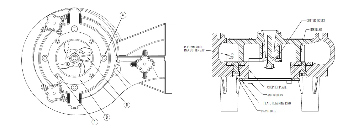
ADJUST CUTTER CLEARANCE ON CHOPPER PUMP
Disconnect power before adjusting chopper clearance; always keep fingers and hands away from chopper parts.
- First install the chopper plate (Item D) into the volute. It may be helpful to install ½-20 studs into the chopper plate to line up the holes with the corresponding volute holes. You may have to tap the plate all the way down with a rubber hammer.
- Remove the studs and replace with four ½-20 x 1 (Item A) in long socket head screws from beneath the volute, do not tighten.
- Install motor with impeller mounted, tighten motor housing bolts to the volute
- Install the chopper retainer ring (Item B) and tighten the four 3/8 -16 x 1″ long (Item C) socket head cap screws to force the chopper plate up against the impeller and chopper blade
- Next back off these 3/8-16 (Item C) bolts one quarter of a turn. This should give you .015 clearances.
- Tighten the outer four ½ -20 screws (Item A) to 75-85 Ft-lbs.
- Measure the clearance with a feeler gage it should be between .010 and .015.
- Spin impeller with a hex wrench on the Impeller hub screw or use a wooden pry bar to spin impeller to make sure there is no rub.
- If you hear or feel a rub readjust the clearance by loosening the inner 3/8-16″ screws evenly and tightening the ½- 20 screws.
Pump Troubleshooting
Below is a list of common problems and the probable causes: Pump will not start.
- No power to the motor. Check for blown fuse or open circuit breaker.
- Selector switch may be in the Off position.
- Control circuit transformer fuse may be blown.
- Overload heater on starter may be tripped. Push to reset.
Pump will not start and overload heaters trip.
- Turn off power and check motor leads with Megger or ohmmeter for possible ground.
- Check resistance of motor windings. All 3 phases should show the same reading.
- If no grounds exist and the motor windings check OK, remove pump from sump and check for clogged or blocked impeller.
Pump operates with selector switch in Hand position but will not operate in Auto position.
- This indicates trouble in the float level control or the alternator relay.
- Check control panel for trouble.
Pump runs but will not shut off.
- Pump may be air locked. Turn pump off and let set for several minutes, then restart.
- Lower float control may be hung-up in the closed position. Check in sump to be sure control is free.
- Selector switch may be in the Hand position.
Pump does not deliver proper capacity.
- Discharge gate valve may be partially closed or partially clogged.
- Check valve may be partially clogged. Raise level up and down to clear.
- Pump may be running in wrong direction. Low speed pumps can operate in reverse direction without much noise or vibration.
- Discharge head may be too high. Check total head with gauge when pump is operating. Total head is discharge gauge pressure converted to feet plus vertical height from water level in sump to center line of pressure gauge in discharge line. Gauge should be installed on pump side of all valves. Multiply gauge pressure in pounds by 2.31 to get head in feet.
- If pump has been in service for some time and capacity falls off, remove pump and check for wear or clogged impeller.
Motor stops and then restarts after short period but overload heaters in starter do not trip.
- This indicates heat sensors in the motor are tripping due to excessive heat. Impeller may be partially clogged giving a sustained overload but not high enough to trip overload heater switch.
- Motor may be operating out of liquid due to a failed level control.
- Pump may be operating on a short cycle due to sump being too small or from water returning to sump due to a leaking check valve.
PUMP PARTS LIST
C4S(X)P, H3H(X)P, H4H(X)P, S4M(X)P, S4P(X)P, S4HV(X)P and S4MV(X)P
For use with product built with Premium Efficient motor.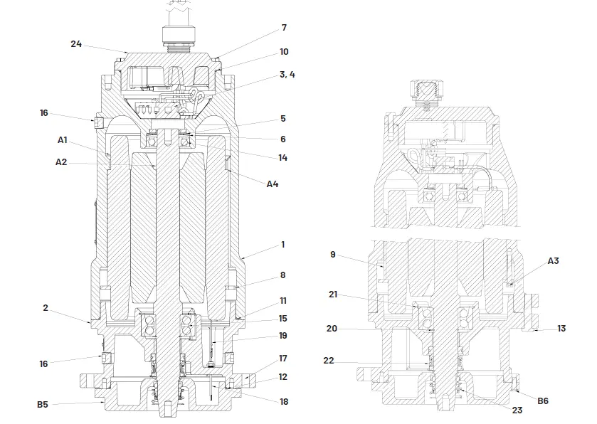
| Ref.No. | Part No. | Part Description | Qty. |
| 1 | 28010D000 | MOTOR HOUSING | 1 |
| 2 | 27818D010 | BEARING HOUSING | 1 |
| 3 | 27882A009 | TERMINAL BLOCK | 1 |
| 4 | 06106A069 | SCREW (TERMINAL BLOCK) | 2 |
| 5 | 110650033 | SCREEN | 1 |
| 6 | 19331A007 | WASHER SPRING (THRUST) | 1 |
| 7 | 19101A017 | CAP SCREW (CORD CAP) | 6 |
| 8 | 026032103 | STATOR RING | 1 |
| 9 | 05818A090 | KEY SQ. 5/32 | 1 |
| 10 | 001500191 | O-RING (CORD CAP) | 1 |
| 11 | 05876A135 | O-RING (MOTOR HOUSING) | 1 |
| 12 | 05876A121 | O-RING (SEAL PLATE) | 1 |
| 13 | 19103A048 | SCREW CAP 1/2–13 x 2.5 LG | 4 |
| 14 | 000650111 | BALL BEARING UPPER | 1 |
| 15 | 071670181 | DOUBLE ROW BALL BEARING LOWER | 1 |
| 16 | 009240101 | PIPE PLUG 1/2 SOCKET HEAD BRASS | 3 |
| Ref.No. | Part No. | Part Description | Qty. |
| 17 | 19103A048 | CAPSCREW – S4M(X)P, S4MV(X)P, S4HV(X)P | 4 |
| 19103A060 | CAPSCREW – S4P(X)P, H3H(X)P, H4H(X)P, C4S(X)P | 4 | |
| 18 | 109010011 | SEAL FAILURE PROBE | 2 |
| 19 | 109000025 | SENSOR WIRES | 1 |
| 20 | 12558A017 | RETAINING RING EXTERNAL | 1 |
| 21 | 009740031 | RETAINING RING INTERNAL | 1 |
| 22 | 110491001 | UPPER SEAL | 1 |
| 23 | 009201001 | LOWER SEAL | 1 |
| 24 | 152880315 | CORD CAP ASSEMBLY – 10-4 SOOW | 1 |
| 152880325 | CORD CAP ASSEMBLY – 8-4 W | 1 | |
| 152880335 | CORD CAP ASSEMBLY – 6-4 W | 1 | |
| B5 | 278190003 | SEAL PLATE – S4M(X)P, S4MV(X)P, S4HV(X)P | 1 |
| 278190103 | SEAL PLATE- S4P(X)P, H3H(X)P, H4H(X)P, C4S(X)P | 1 | |
|
B6 | 07597A017 | BOLT(SEAL PLATE) S4M(X)P, S4MV(X)P, S4HV(X)P | 4 |
| 047560061 | BOLT(SEAL PLATE) S4P(X)P, H3H(X)P, H4H(X) P, C4S(X)P | 4 |
HYDRAULIC ENDS PART LIST
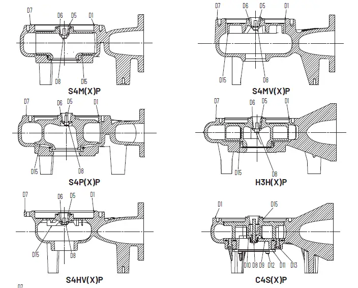

| Item No. | Description | S4M(X)P | S4MV(X)P | S4HV(X)P | S4P(X)P | H3H(X)P | H4H(X)P | C4S(X)P |
| D1 | O-RING | 001500581 | 001500581 | 001500581 | 05876A136 | 05876A136 | 05876A136 | 05876A136 |
| D5 | IMPELLER KEY | 083460033 | 083460011 | 083460011 | 083460033 | 083460033 | 083460033 | 083460033 |
| D6 | WASHER – IMPELLER | 080230001 | 080230001 | 080230011 | 080230001 | 080230001 | 080230001 | N/A |
| D7 | VOLUTE | 070680015 | 070800002 | 0082120002 | 137210015 | 151540015 | 151470015 | 153300002 |
| D8 | IMP BOLT | 005680021 | 005680021 | 029210041 | 005680021 | 005680021 | 005680021 | 005680191 |
| D9 | CHOPPER PLATE | N/A | N/A | N/A | N/A | N/A | N/A | 153340002 |
| D10 | CHOPPER BLADE | N/A | N/A | N/A | N/A | N/A | N/A | 153320002 |
| D11 | RETAINER PLATE | N/A | N/A | N/A | N/A | N/A | N/A | 153330001 |
| D12 | SCREW-CAP (RETAINER) | N/A | N/A | N/A | N/A | N/A | N/A | 06106A028 |
| D13 | SCREW-CAP (CHOPPER PLATE) | N/A | N/A | N/A | N/A | N/A | N/A | 005680021 |
| D14 | SCREW – FLAT HEAD SOCKET | N/A | N/A | N/A | N/A | N/A | N/A | 07597A037 |
| D15 | IMPELLER | 070710012 | 070810002 | 0082130052 | 137220012 | 151465002 | 151465002 | 153310002 |
MOTOR PARTS GROUP
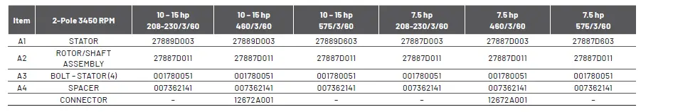
| Item | 4-Pole 1750 RPM | 10 – 15 hp 208-230/3/60 | 10 – 15 hp 460/3/60 | 10 – 15 hp 575/3/60 | 5 – 7.5 hp 208-230/1/60 | 5 – 7.5 hp 208-230/3/60 | 5 – 7.5 hp 460/3/60 | 5 – 7.5 hp 575/3/60 |
| A1 | STATOR | 27886D003 | 27886D003 | 27886D603 | 27885D001 | 27884D003 | 27884D003 | 27884D603 |
| A2 | ROTOR/SHAFT ASSEMBLY | 27886D011 | 27886D011 | 27886D011 | 27885D011 | 27884D011 | 27884D011 | 27884D011 |
| A3 | BOLT – STATOR (4) | 06106A070 | 06106A070 | 06106A070 | 001780051 | 001780041 | 001780041 | 001780041 |
| A4 | SPACER | – | – | – | 007362141 | 007362141 | 007362141 | 007362141 |
| CONNECTOR | – | 12672A001 | – | – | – | 12672A001 | – |
| Item | 6-Pole 1150 RPM | 3 – 5 hp 208-230/3/60 | 3 – 5 hp 460/3/60 | 3 – 5 hp 575/3/60 |
| A1 | STATOR | 27883D003 | 27883D003 | 27883D603 |
| A2 | ROTOR/SHAFT ASSEMBLY | 27883D011 | 27883D011 | 27883D011 |
| A3 | BOLT – STATOR (4) | 001780051 | 001780051 | 001780051 |
| A4 | SPACER | 007362141 | 007362141 | 007362141 |
| CONNECTOR | – | 12672A001 | – |
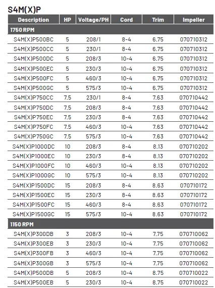
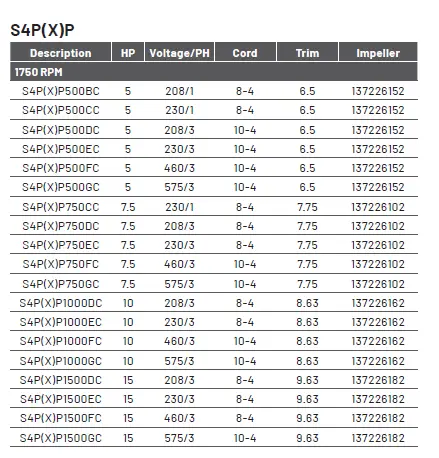
IMPELLER PARTS LIST
H3H(X)P : H4H(X)P
| H3H(X)P500BC | 5 | 208/1 | 8-4 | 7.50 | 151465102 | H4H(X)P500BC | 5 | 208/1 | 8-4 | 7.50 | 151465102 | |
| H3H(X)P500CC | 5 | 230/1 | 8-4 | 7.50 | 151465102 | H4H(X)P500CC | 5 | 230/1 | 8-4 | 7.50 | 151465102 | |
| H3H(X)P500DC | 5 | 208/3 | 10-4 | 7.50 | 151465102 | H4H(X)P500DC | 5 | 208/3 | 10-4 | 7.50 | 151465102 | |
| H3H(X)P500EC | 5 | 230/3 | 10-4 | 7.50 | 151465102 | H4H(X)P500EC | 5 | 230/3 | 10-4 | 7.50 | 151465102 | |
| H3H(X)P500FC | 5 | 460/3 | 10-4 | 7.50 | 151465102 | H4H(X)P500FC | 5 | 460/3 | 10-4 | 7.50 | 151465102 | |
| H3H(X)P500GC | 5 | 575/3 | 10-4 | 7.50 | 151465102 | H4H(X)P500GC | 5 | 575/3 | 10-4 | 7.50 | 151465102 | |
| H3H(X)P750CC | 7.5 | 230/1 | 8-4 | 8.00 | 151465082 | H4H(X)P750CC | 7.5 | 230/1 | 8-4 | 8.00 | 151465082 | |
| H3H(X)P750DC | 7.5 | 208/3 | 8-4 | 8.00 | 151465082 | H4H(X)P750DC | 7.5 | 208/3 | 8-4 | 8.00 | 151465082 | |
| H3H(X)P750EC | 7.5 | 230/3 | 8-4 | 8.00 | 151465082 | H4H(X)P750EC | 7.5 | 230/3 | 8-4 | 8.00 | 151465082 | |
| H3H(X)P750FC | 7.5 | 460/3 | 10-4 | 8.00 | 151465082 | H4H(X)P750FC | 7.5 | 460/3 | 10-4 | 8.00 | 151465082 | |
| H3H(X)P750GC | 7.5 | 575/3 | 10-4 | 8.00 | 151465082 | H4H(X)P750GC | 7.5 | 575/3 | 10-4 | 8.00 | 151465082 | |
| H3H(X)P1000DC | 10 | 208/3 | 8-4 | 8.50 | 151465062 | H4H(X)P1000DC | 10 | 208/3 | 8-4 | 8.63 | 151465142 | |
| H3H(X)P1000EC | 10 | 230/3 | 8-4 | 8.50 | 151465062 | H4H(X)P1000EC | 10 | 230/3 | 8-4 | 8.63 | 151465142 | |
| H3H(X)P1000FC | 10 | 460/3 | 10-4 | 8.50 | 151465062 | H4H(X)P1000FC | 10 | 460/3 | 10-4 | 8.63 | 151465142 | |
| H3H(X)P1000GC | 10 | 575/3 | 10-4 | 8.50 | 151465062 | H4H(X)P1000GC | 10 | 575/3 | 10-4 | 8.63 | 151465142 | |
| H3H(X)P1500DC | 15 | 208/3 | 8-4 | 10.00 | 151465002 | H4H(X)P1500DC | 15 | 208/3 | 8-4 | 9.50 | 151465022 | |
| H3H(X)P1500EC | 15 | 230/3 | 8-4 | 10.00 | 151465002 | H4H(X)P1500EC | 15 | 230/3 | 8-4 | 9.50 | 151465022 | |
| H3H(X)P1500FC | 15 | 460/3 | 8-4 | 10.00 | 151465002 | H4H(X)P1500FC | 15 | 460/3 | 8-4 | 9.50 | 151465022 | |
| H3H(X)P1500GC | 15 | 575/3 | 10-4 | 10.00 | 151465002 | H4H(X)P1500GC | 15 | 575/3 | 10-4 | 9.50 | 151465022 |
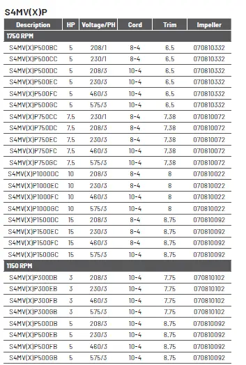
S4HV(X)P
| S4HV(X)P750DD | 7.5 | 208/3 | 8-4 | 4.63 | 082130172 |
| S4HV(X)P750ED | 7.5 | 230/3 | 8-4 | 4.63 | 082130172 |
| S4HV(X)P750FD | 7.5 | 460/3 | 10-4 | 4.63 | 082130172 |
| S4HV(X)P750GD | 7.5 | 575/3 | 10-4 | 4.63 | 082130172 |
| S4HV(X)P1000DD | 10 | 208/3 | 8-4 | 5 | 082130042 |
| S4HV(X)P1000ED | 10 | 230/3 | 8-4 | 5 | 082130042 |
| S4HV(X)P1000FD | 10 | 460/3 | 10-4 | 5 | 082130042 |
| S4HV(X)P1000GD | 10 | 575/3 | 10-4 | 5 | 082130042 |
C4S(X)P
| Description | HP | Voltage/PH | Cord | Trim | Impeller |
| 1750 RPM | |||||
| C4S(X)P750CC | 7.5 | 230/1 | 8-4 | 7 | 153310192 |
| C4S(X)P750DC | 7.5 | 208/3 | 8-4 | 7 | 153310192 |
| C4S(X)P750EC | 7.5 | 230/3 | 8-4 | 7 | 153310192 |
| C4S(X)P750FC | 7.5 | 460/3 | 10-4 | 7 | 153310192 |
| C4S(X)P750GC | 7.5 | 575/3 | 10-4 | 7 | 153310192 |
| C4S(X)P1000DC | 10 | 208/3 | 8-4 | 7 | 153310192 |
| C4S(X)P1000EC | 10 | 230/3 | 8-4 | 7 | 153310192 |
| C4S(X)P1000FC | 10 | 460/3 | 10-4 | 7 | 153310192 |
| C4S(X)P1000GC | 10 | 575/3 | 10-4 | 7 | 153310192 |
| C4S(X)P1500DC | 15 | 208/3 | 8-4 | 8.5 | 153310072 |
| C4S(X)P1500EC | 15 | 230/3 | 8-4 | 8.5 | 153310072 |
| C4S(X)P1500FC | 15 | 460/3 | 8-4 | 8.5 | 153310072 |
| C4S(X)P1500GC | 15 | 575/3 | 10-4 | 8.5 | 153310072 |
| 1150 RPM | |||||
| C4S(X)P300DB | 3 | 208/3 | 10-4 | 7.25 | 153310172 |
| C4S(X)P300EB | 3 | 230/3 | 10-4 | 7.25 | 153310172 |
| C4S(X)P300FB | 3 | 460/3 | 10-4 | 7.25 | 153310172 |
| C4S(X)P300GB | 3 | 575/3 | 10-4 | 7.25 | 153310172 |
| C4S(X)P500DB | 5 | 208/3 | 10-4 | 8.88 | 153310122 |
| C4S(X)P500EB | 5 | 230/3 | 10-4 | 8.88 | 153310122 |
| C4S(X)P500FB | 5 | 460/3 | 10-4 | 8.88 | 153310122 |
| C4S(X)P500GB | 5 | 575/3 | 10-4 | 8.88 | 153310122 |
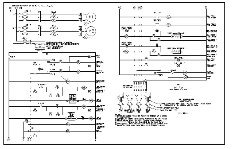
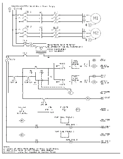
WIRING DIAGRAMS
WARRANTY
Pentair Hydromatic® warrants its products against defects in material and workmanship for a period of 12 months from installation date or 18 months from manufacturing date, whichever occurs first – provided that such products are used in compliance with the requirements of the Pentair Hydromatic catalog and technical manuals for use in pumping raw sewage, municipal wastewater or similar, abrasive-free, noncorrosive liquids.
During the warranty period and subject to the conditions set forth, Pentair Hydromatic, at its discretion, will repair or replace to
the original user, the parts that prove defective in materials and workmanship. Pentair Hydromatic reserves the right to change or improve its products or any portions thereof without being obligated to provide such a change or improvement for prior sold and/or shipped units.
Start-up reports and electrical schematics may be required to support warranty claims. Submit at the time of start up through the Pentair Hydromatic website: http://forms.pentairliterature.com/startupform/startupform.asp?type=h. Warranty is effective only
if Pentair Hydromatic authorized control panels are used. All seal fail and heat sensing devices must be hooked up, functional and monitored or this warranty will be void. Pentair Hydromatic will cover only the lower seal and labor thereof for all dual seal pumps. Under no circumstance will Pentair Hydromatic be responsible for the cost of field labor, travel expenses, rented equipment, removal/reinstallation costs or freight expenses to and from the factory or an authorized Pentair Hydromatic service facility.
This limited warranty will not apply: (a) to defects or malfunctions resulting from failure to properly install, operate or maintain the unit in accordance with the printed instructions provided; (b) to failures resulting from abuse, accident or negligence; (c) to normal maintenance services and parts used in connection with such service; (d) to units that are not installed in accordance with applicable local codes, ordinances and good trade practices; (e) if the unit is moved from its original installation location; (f) if unit is used for purposes other than for what it is designed and manufactured; (g) to any unit that has been repaired or altered by anyone other than Pentair Hydromatic or an authorized Pentair Hydromatic service provider; (h) to any unit that has been repaired using non factory specified/OEM parts.
Warranty Exclusions: PENTAIR HYDROMATIC MAKES NO EXPRESS OR IMPLIED WARRANTIES THAT EXTEND BEYOND THE DESCRIPTION ON THE FACE HEREOF. PENTAIR HYDROMATIC SPECIFICALLY DISCLAIMS THE IMPLIED WARRANTIES OF MERCHANTABILITY AND FITNESS FOR ANY PARTICULAR PURPOSE.
Liability Limitation: IN NO EVENT SHALL PENTAIR HYDROMATIC BE LIABLE OR RESPONSIBLE FOR CONSEQUENTIAL, IN-CIDENTAL OR SPECIAL DAMAGES RESULTING FROM OR RELATED IN ANY MANNER TO ANY PENTAIR HYDROMATIC PROD-UCT OR PARTS THEREOF. PERSONAL INJURY AND/OR PROPERTY DAMAGE MAY RESULT FROM IMPROPER INSTALLATION. PENTAIR HYDROMATIC DISCLAIMS ALL
LIABILITY, INCLUDING LIABILITY UNDER THIS WARRANTY, FOR IMPROPER INSTALLATION. PENTAIR HYDROMATIC RECOM-MENDS INSTALLATION BY PROFESSIONALS.
Some states do not permit some or all of the above warranty limitations or the exclusion or limitation of incidental or consequential damages and therefore such limitations may not apply to you. No warranties or representations at any time made by any representatives of Pentair Hydromatic shall vary or expand the provision hereof.
1101 Myers Parkway Ashland, OH 44805 Ph: 419.289.1144
490 Pinebush Rd., Unit 4 Cambridge, Ontario Canada N1t 0a5
Ph: 800.363.7867
pentair.com
All indicated Pentair trademarks and logos are property of Pentair. Third party registered and unregistered trademarks and logos are the property of their respective owners. Because we are continuously improving our products and services, Pentair reserves the right to change specifications without prior notice. Pentair is an equal opportunity employer.
©2023 Pentair. All Rights Reserved.

 Submersible Solids Handling Pump Instruction Manual")

 Submersible Solids Handling Pump User Manual")


