Salus Rx10rf - Wiring Diagram User Guide

Salus Rx10rf - Wiring Diagram User Guide

SALUS LOGO

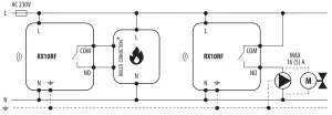
RX10RF – Wiring diagram
User Guide

SALUS RX10RF Wiring diagram

LEGEND

Battery poweredBattery-poweredSALUS T30NC 230V M30 1 5 Wiring diagram - Wireless communicationWireless communication
L, N230V AC power supplySALUS T30NC 230V M30 1 5 Wiring diagram - PumpPump
SALUS T30NC 230V M30 1 5 Wiring diagram - FuseFuseSALUS T30NC 230V M30 1 5 Wiring diagram - Valve actuatorValve actuator
COM, NO, NCVoltage free outputSALUS T30NC 230V M30 1 5 Wiring diagram - Temperature sensorTemperature sensor
S, S1, S2Input terminalsSALUS T30NC 230V M30 1 5 Wiring diagram - speed 230V AC fan3-speed 230V AC fan
SL230V AC voltage outputSALUS T30NC 230V M30 1 5 Wiring diagram - Light bulb or other loadA light bulb or another load
SALUS T30NC 230V M30 1 5 Wiring diagram - Contact normally openContact normally openSALUS T30NC 230V M30 1 5 Wiring diagram -Thermoelectric actuatorThermoelectric actuator
SALUS T30NC 230V M30 1 5 Wiring diagram - Contact normally closedContact normally closedSALUS T30NC 230V M30 1 5 Wiring diagram -Time programmerTime programmer
SALUS T30NC 230V M30 1 5 Wiring diagram - switchNC/COM/NO switchSALUS T30NC 230V M30 1 5 Wiring diagram -External normally open contactExternal normally open contact
SALUS T30NC 230V M30 1 5 Wiring diagram - Boiler connectionBoiler – Boiler connection * – Boiler’s contacts for ON/OFF thermostat (according to the boiler’s instructions)SALUS T30NC 230V M30 1 5 Wiring diagram -Voltage converterVoltage converter

Documents / Resouces

Download manual
Here you can download full pdf version of manual, it may contain additional safety instructions, warranty information, FCC rules, etc.


Related Manuals