Trinasolar DE09M.05 Solar Panel
This document is intended to add mounting options in addition to the already existing and described methods within the Trina Solar User Manuals.
In order to achieve the best use of installation of systems, mounting system shall be designed or selected according to the project requirements. Fixation (including bolts, clamps, hooks, etc.) used in a system shall not be failure (malfunctioned to cause loose or any other issues which may damage the PV modules) in any circumstance. Trina Solar recommends a minimum clamp length of 50 mm (1.97 inch) with thickness of ≥3 mm (0.12 inch) for highstrength metal clamps.
INSTALLATION
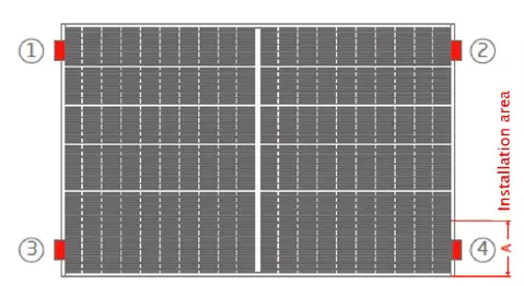
Short side clamping with 4 clamps and rail underneath the module short side
| Graphic view | Description |
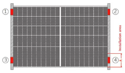 | Clamp position can be within the range 0 – xxx mm (clamping range refers to Table 1) for all 4 clamps attached to the module short side; clamping range can be asymmetrical, clamp 1 & 2 can have a different position from the module edge compared to clamp 3 & 4. |
Legend
| Solid mounting rail under the module which fully supports the module frame from underneath and is also used to fix the clamps into. | |
| Module clamp which has to fulfill Trina’s minimum requirements in terms of grip length and grip depth. |
Table 1: Maximum mechanical test loads and clamping ranges for option 1.
| Product Code | Maximum Test Load (Front side +) | Maximum Test Load (Back side -) | Clamping range (A) |
| DE09 DE09.08 DE09.05 | 2400 Pa | 2000 Pa | 0 – 200mm |
| DE08M(II) DE08M.08(II) DD08M.08(II) | 2000 Pa | 1800 Pa | 0 – 200mm |
| DEG8MC.20(II) | 1800 Pa | 1600 Pa | 0 – 200mm |
| DE06M.08(II) DE06M(II) DD06M.05(II) DE06X.05(II) | 2000Pa | 1800 Pa | 0 – 200mm |
| DE15M(II) | 1600 Pa | 1000 Pa | 0 – 200mm |
| DEG15MC.20(II) PEG15H.20 | 1600 Pa | 1000 Pa | 0 – 200mm |
| DE15V(II) | 1200 Pa | 800 Pa | 0 – 200mm |
| DEG15VC.20(II) | 1300 Pa | 1000 Pa | 0 – 200mm |
| DE17M(II) | 1600 Pa | 1000 Pa | 0 – 200mm |
| DEG17MC.20(II) | 1600 Pa | 1000 Pa | 0 – 200mm |
| DE18M(II) | 1200 Pa | 1000 Pa | 0 – 200mm |
| DEG18MC.20(II) | 1300 Pa | 1000 Pa | 0 – 200mm |
| DE19 DEG19C.20 | 1200 Pa | 800 Pa | 0 – 200mm |
| DE20 DEG20C.20 | 1200 Pa | 800 Pa | 0 – 200mm |
| DE21 DEG21C.20 | 1200 Pa | 800 Pa | 0 – 200mm |
Short side slide-in/insertion
Graphic view
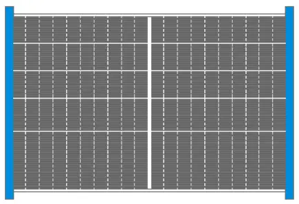
Description
Module short sides are inserted into slide-in rails completely.
Legend
![]()
Solid mounting rail supporting the module frame from underneath and from the top (C-shape type of rail) in which the module frame is held, no clamp needed.
Table 2: Maximum mechanical test loads for option 2.
| Product Code | Maximum Test Load (Front side +) | Maximum Test Load (Back side -) |
| DE09 DE09.08 DE09.05 | 2400 Pa | 2000 Pa |
| DE08M(II) DE08M.08(II) DD08M.08(II) | 2000 Pa | 1800 Pa |
| DEG8MC.20(II) | 1800 Pa | 1600 Pa |
| DE06M.08(II) DE06M(II) DD06M.05(II) DE06X.05(II) | 2000 Pa | 1800 Pa |
| DE15M(II) | 1000 Pa | 1000 Pa |
| DEG15MC.20(II) PEG15H.20 | 1000 Pa | 1000 Pa |
| DE15V(II) | 1200 Pa | 800 Pa |
| DEG15VC.20(II) | 1300 Pa | 1000 Pa |
| DE17M(II) | 1000 Pa | 1000 Pa |
| DEG17MC.20(II) | 1000 Pa | 1000 Pa |
| DE18M(II) | 1000 Pa | 1000 Pa |
| DEG18MC.20(II) | 1000 Pa | 1000 Pa |
| DE19 DEG19C.20 | 1200 Pa | 800 Pa |
| DE20 DEG20C.20 | 1200 Pa | 800 Pa |
| DE21 DEG21C.20 | 1200 Pa | 800 Pa |
Short side clamping with 4 clamps and only punctual support underneath module frame
| Graphic view | Description |
 | Clamp position can be within the range 0 – xxx mm (clamping range refers to Table 3) for all 4 clamps attached to the module short side, clamping range can be asymmetrical, clamp 1&2 can have a different position form the module edge compared to clamp 3 & 4. |
Legend
![]()
Module clamp which has to fulfill Trina’s minimum requirements in terms of grip length and grip depth.
Table 3: Maximum mechanical test loads and clamping ranges for option 3.
| Product Code | Maximum Test Load (Front side +) | Maximum Test Load (Back side -) | Clamping range (A) |
| DE09 DE09.08 DE09.05 | 2400 Pa | 1800 Pa | 0 – 200mm |
| DE08M(II) DE08M.08(II) DD08M.08(II) | 1800 Pa | 1800 Pa | 0 – 200mm |
| DEG8MC.20(II) | 1600 Pa | 1600 Pa | 0 – 200mm |
| DE06M.08(II) DE06M(II) DD06M.05(II) DE06X.05(II) | 1800 Pa | 1800 Pa | 0 – 200mm |
| DE15M(II) | 1600 Pa | 1000 Pa | 0 – 200mm |
| DEG15MC.20(II) PEG15H.20 | 1600 Pa | 1000 Pa | 0 – 200mm |
| DE15V(II) | 1200 Pa | 800 Pa | 0 – 200mm |
| DEG15VC.20(II) | 1300 Pa | 1000 Pa | 0 – 200mm |
| DE17M(II) | 1600 Pa | 1000 Pa | 0 – 200mm |
| DEG17MC.20(II) | 1600 Pa | 1000 Pa | 0 – 200mm |
| DE18M(II) | 1300 Pa | 1000 Pa | 0 – 200mm |
| DEG18MC.20(II) | 1300 Pa | 1000 Pa | 0 – 200mm |
| DE19 DEG19C.20 | 1200 Pa | 800 Pa | 0 – 200mm |
| DE20 DEG20C.20 | 1200 Pa | 800 Pa | 0 – 200mm |
| DE21 DEG21C.20 | 1200 Pa | 800 Pa | 0 – 200mm |
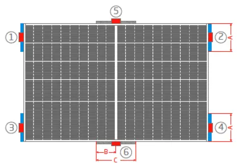
Long side clamping and only punctual support underneath module frame
| Graphic view | Description |
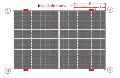 | Clamp position can be within the range xxx – xxx mm (clamping range refers to Table 4) for all 4 clamps attached to the module long side; the clamps 1 & 3 can have a different distance to the edge than the clamps 2 & 4 (asymmetrical clamping). |
Legend
![]()
Module clamp which has to fulfill Trina’s minimum requirements in terms of grip length and grip depth.
Table 4: Maximum mechanical test loads and clamping ranges for option 4.
| Product Code | Maximum Test Load (Front side +) | Maximum Test Load (Back side -) | Clamping range | |
| A | B | |||
| DE09 | ||||
| DE09.08 | 2400 Pa | 2000 Pa | 100 | 500 |
| DE09.05 | ||||
| DE09 DE09.08 | 3600 Pa | 3000 Pa | 200 | 400 |
| DE09.05 | ||||
| DE08M(II) DE08M.08(II) DD08M.08(II) | 1800 Pa | 1800 Pa | 100 | 600 |
| DEG8MC.20(II) | 1800 Pa | 1800 Pa | 100 | 600 |
| DE06M.08(II) | ||||
| DE06M(II) DD06M.05(II) | 1800 Pa | 1800 Pa | 100 | 600 |
| DE06X.05(II) | ||||
| DE15M(II) | 1800 Pa | 1800 Pa | 200 | 600 |
| DEG15MC.20(II) | 1800 Pa | 1800 Pa | 200 | 600 |
| DE15V(II) DEG15VC.20(II) | 1200 Pa | 1200 Pa | 200 | 600 |
| DE17M(II) | 1800 Pa | 1800 Pa | 200 | 600 |
| DEG17MC.20(II) | 1800Pa | 1800 Pa | 200 | 600 |
| DE18M(II) | 1700 Pa | 1700 Pa | 200 | 600 |
| DEG18MC.20(II) | 1700 Pa | 1700 Pa | 200 | 600 |
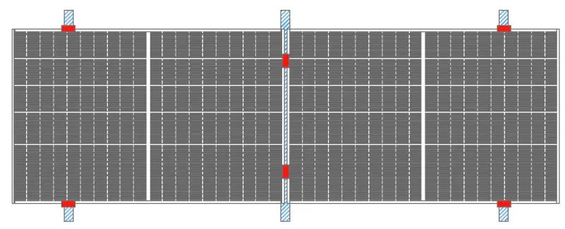
Long side 4 points clamping with crossbeam
| Graphic view | Description |
| Clamp position can be within the range xxx – xxx mm (clamping range refers to Table 5) for all 4 clamps attached to the module long side; the clamps 1 & 3 can have a different distance to the edge than the clamps 2 & 4 (asymmetrical clamping). |
Legend
![]()
Module clamp, which has to fulfill Trina’s minimum requirements in terms of grip length and grip depth. Higher load as per Installation Manual.
Table 5: Maximum mechanical test loads and clamping ranges for option 5.
| Product Code | Maximum Test Load (Front side +) | Maximum Test Load (Back side -) | Clamping range | |
| A | B | |||
| DE08M(II) DE08M.08(II) DD08M.08(II) | 1800 Pa | 1800 Pa | 100 | 600 |
| DE08M(II) DE08M.08(II) DD08M.08(II) | 2000 Pa | 2000 Pa | 200 | 500 |
| DE09 DE09.08 DE09.05 | 2400 Pa | 2000 Pa | 100 | 500 |
| DE09 DE09.08 DE09.05 | 3600 Pa | 3000 Pa | 200 | 400 |
| DE15V(II) DEG15VC.20(II) | 1000 Pa | 800 Pa | 100 | 600 |
| DE15V(II) DEG15VC.20(II) | 1200 Pa | 1200 Pa | 200 | 500 |
| DD06M.05(II) DE06X.05(II) | 1800 Pa | 1800 Pa | 100 | 600 |
| DD06M.05(II) DE06X.05(II) | 2000 Pa | 2000 Pa | 200 | 500 |
Short side 4 points clamping with crossbeam
| Graphic view | Description |
 | Clamp position can be within the range xxx – xxx mm (clamping range refers to Table 6) for all 4 clamps attached to the module long side; the clamps 1 & 2 can have a different distance to the edge than the clamps 3 & 4 (asymmetrical clamping). |
Legend
![]()
Module clamp, which has to fulfill Trina’s minimum requirements in terms of grip length and grip depth.
Table 6: Maximum mechanical test loads and clamping ranges for option 6.
| Product Code | Maximum Test Load (Front side +) | Maximum Test Load (Back side -) | Clamping range (A) |
| DE09 DE09.08 DE09.05 | 2400 Pa | 2400 Pa | 150-250 |
| DE17M(II) | 1800 Pa | 1200 Pa | 150-250 |
| DE18M(II) | 1600 Pa | 1000 Pa | 150-250 |
| DE08M(II) DE08M.08(II) DD08M.08(II) | 2400 Pa | 2400 Pa | 150-250 |
Four long side clamps (1-4) and only punctual support underneath module frame and two additional punctual support points (5 & 6) with/without clamps
| Graphic view | Description |
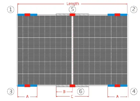 | Clamp position can be within the range xxx – xxx mm (clamping range refers to Table 7) for all 4 clamps attached to the module long side; the clamps 1 & 3 can have a different distance to the edge than the clamps 2 & 4 (asymmetrical clamping); the support points 5 & 6 use with clamps. |
Legend
![]()
Module clamp, which has to fulfill Trina’s minimum requirements in terms of grip length and grip depth. Higher load as per Installation Manual.
Table 7: Maximum mechanical test loads and clamping ranges for option 7.
| Product Code | Maximum Test Load (Front side +) | Maximum Test Load (Back side -) | Clamping range | ||
| A | B | C | |||
| DE09 | |||||
| DE09.08 | 3600 Pa | 2400 Pa | 0-200 | 0-200 | 400 |
| DE09.05 | |||||
| DE18M(II) | 2400 Pa | 1800 Pa | 0-200 | 0-200 | 400 |
| DE15V(II) DEG15VC.20(II) | 2100 Pa | 1500 Pa | 0-200 | 0-200 | 400 |
| DE06X.05(II) | 3600 Pa | 2400 Pa | 0-200 | 0-200 | 400 |
NOTE:
The support points 5 & 6 can also use without clamps, if so, the maximum test load (back side -) will be
- 1800 Pa for DE09 / DE09.08 / DE09.05
- 1500 Pa for DE18M(II)
- 800 Pa for DE15V(II) / DEG15VC.20(II)
- 1800 Pa for DE06X.05(II)
Four short side clamps (1-4) and only punctual support underneath module frame and two additional punctual support points (5 & 6) with/without clamps
| Graphic view | Description |
 | Clamp position can be within the range 0 – xxx mm (clamping range refers to Table 8) for all 4 clamps attached to the module short side, clamping range can be asymmetrical, clamp 1&2 can have a different position form the module edge compared to clamp 3 & 4; the support points 5 & 6 use with clamps. |
Legend
![]()
Module clamp, which has to fulfill Trina’s minimum requirements in terms of grip length and grip depth.
Maximum mechanical test loads and clamping ranges for option 8.
| Product Code | Maximum Test Load (Front side +) | Maximum Test Load (Back side -) | Clamping range | ||
| A | B | C | |||
| DE09 DE09.08 DE09.05 | 3000 Pa | 2400 Pa | 0-200 | 0-200 | 600 |
| DE08M(II) DE08M.08(II) DD08M.08(II) | 2000 Pa | 2000 Pa | 0-200 | 0-200 | 600 |
| DEG8MC.20(II) | 1800 Pa | 1800 Pa | 0-200 | 0-200 | 600 |
| DE15V(II) DEG15VC.20(II) | 1500 Pa | 1500 Pa | 0-200 | 0-200 | 600 |
| DE18M(II) | 1800 Pa | 1800 Pa | 0-200 | 0-200 | 600 |
NOTE:
The support points 5 & 6 can also use without clamps, if so, the maximum test load (back side -) will be
- 1800Pa for DE09 / DE09.05 / DE09.08
- 1800 Pa for DE08M(II) / DE08M.08(II) / DD08M.08(II)
- 1600 Pa for DEG8MC.20(II)
- 800 Pa for DE15V(II) / DEG15VC.20(II)
- 1000 Pa for DE18M(II)
Hybrid clamping with clamps on long and short side and solid rails supporting from underneath
Graphic view
Legend
| Solid mounting rail under the module which fully supports the module frame from underneath and is also used to fix the clamps into. | |
| Module clamp, which has to fulfill Trina’s minimum requirements in terms of grip length and grip depth. |
Maximum mechanical test loads and clamping ranges for option 9.
| Product Code | Maximum Test Load (Front side +) | Maximum Test Load (Back side -) | Clamping range | |
| short side | long side | |||
| DE09 DE09.08 DE09.05 | 2400 Pa | 1800 Pa | 100-250 | 250-450 |
| DE08M(II) DE08M.08(II) DD08M.08(II) | 1800 Pa | 1800 Pa | 100-250 | 250-450 |
| DE15V(II) DEG15VC.20(II) | 1200 Pa | 800 Pa | 100-250 | 250-450 |
| DE17M(II) | 1600 Pa | 1000 Pa | 100-250 | 250-450 |
| DEG17MC.20(II) | 1600 Pa | 1000 Pa | 100-250 | 250-450 |
| DE18M(II) | 1200 Pa | 1000 Pa | 100-250 | 250-450 |
| DEG18MC.20(II) | 1300 Pa | 1000 Pa | 100-250 | 250-450 |
Four clamps which are clamping the module flange from underneath on the long side of the module
| Graphic view | Description | |
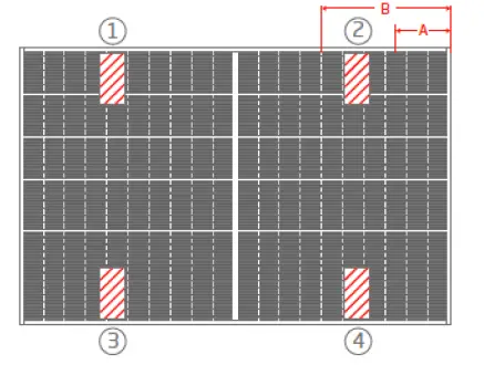 | Four clamps underneath the module are clamping the flange of the long side frame, the module frame is punctually supported from underneath. The clamp position can be within the 0 – xxx mm (clamping range refers to Table 10) for all 4 clamps attached to the module. The clamps 1 & 3 can have a different distance to the edge than the clamps 2 & 4 (asymmetrical clamping). | |
| Legend | ||
| Module clamps | ||
Table 10: Maximum mechanical test loads and clamping ranges for option 10.
| Product Code | Maximum Test Load (Front side +) | Maximum Test Load (Back side -) | Clamping range | |
| A | B | |||
| DE09 DE09.08 DE09.05 | 2400 Pa | 2000 Pa | 100 | 500 |
| DE08M(II) DE08M.08(II) DD08M.08(II) | 1800 Pa | 1800 Pa | 100 | 600 |
| DE15V(II) DEG15VC.20(II) | 1200 Pa | 1200 Pa | 200 | 600 |
| DE17M(II) | 1800 Pa | 1800 Pa | 200 | 600 |
| DEG17MC.20(II) | 1800 Pa | 1800 Pa | 200 | 600 |
| DE18M(II) | 1700 Pa | 1700 Pa | 200 | 600 |
| DEG18MC.20(II) | 1700 Pa | 1700 Pa | 200 | 600 |
| DD06M.05(II) DE06X.05(II) | 1800 Pa | 1800 Pa | 100 | 600 |
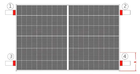
Four clamps which are clamping the module flange from underneath on the short side of the module
| Graphic view | Description | |
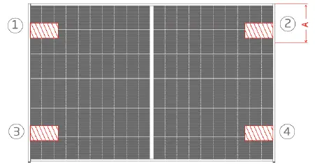 | Four clamps underneath the module are clamping the flange of the short side frame, the module frame is punctually supported from underneath. The clamp position can be within the 0 – xxx mm (clamping range refers to Table 11) for all 4 clamps attached to the module. The clamps 1 & 2 can have a different distance to the edge than the clamps 3 & 4 (asymmetrical clamping). | |
| Legend | ||
| Module clamps | ||
Table 11: Maximum mechanical test loads and clamping ranges for option 11.
| Product Code | Maximum Test Load (Front side +) | Maximum Test Load (Back side -) | Clamping range (A) |
| DE09 DE09.08 DE09.05 | 2400 Pa | 1800 Pa | 0 – 200 mm |
| DE08M(II) DE08M.08(II) DD08M.08(II) | 1800 Pa | 1800 Pa | 0 – 200 mm |
| DE15V(II) | 1200 Pa | 800 Pa | 0 – 200 mm |
| DEG15VC.20(II) | 1300 Pa | 1000 Pa | 0 – 200 mm |
| DE17M(II) | 1600 Pa | 1000 Pa | 0 – 200 mm |
| DEG17MC.20(II) | 1600 Pa | 1000 Pa | 0 – 200 mm |
| DE18M(II) | 1300 Pa | 1000 Pa | 0 – 200 mm |
| DEG18MC.20(II) | 1300 Pa | 1000 Pa | 0 – 200 mm |
| DD06M.05(II) DE06X.05(II) | 1800 Pa | 1800 Pa | 0 – 200 mm |
Trina Solar Co., LtD.
2 Tianhe Road, Tianhe Photovoltaic Industrial Park, Xinbei District.
Changzhou City, Jiangsu Province, P. R. China.
400 988 0000
The Right of Final Interpretation Belongs to Trina Solar.


