![]() AIO360G
AIO360G
Installation Manual
Name and Function of Each Part
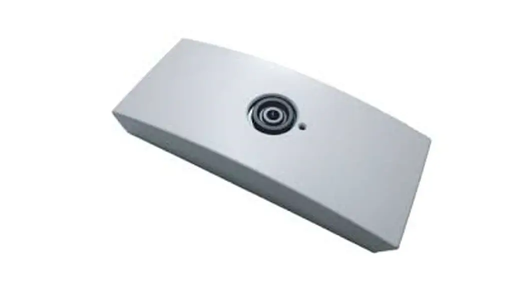
Sensor with the cover attached
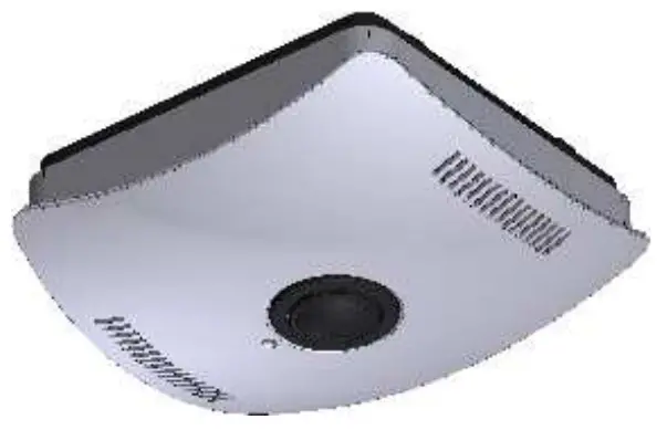
Sensor with the cover removed
Installing the Sensor on the Ceiling
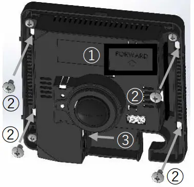
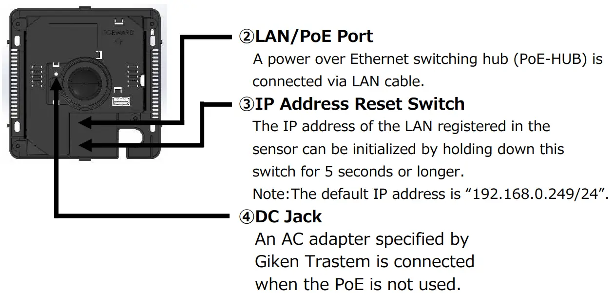
- The direction of the “FORWARD” arrow is captured in the upward direction of the screen.
- Secure the sensor to the ceiling at 4 positions using appropriate screws.
- Connect the LAN cable.
Attaching the Cover
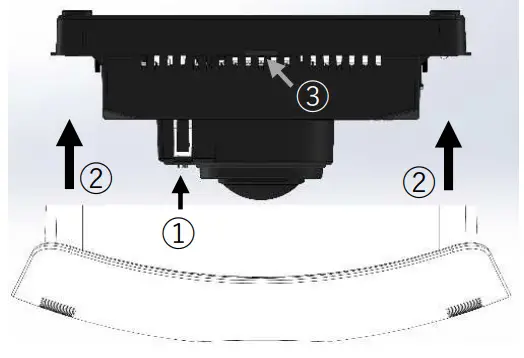
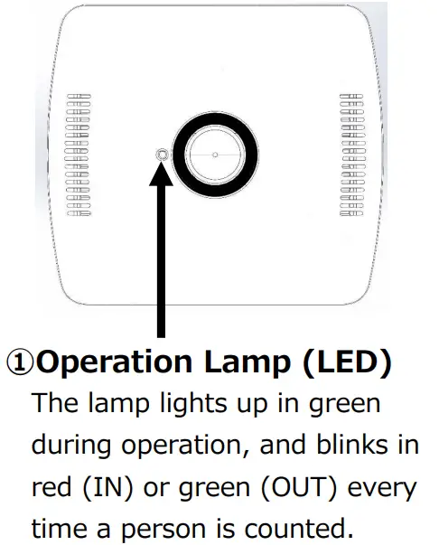
- Check the position of the operation lamp and determine the orientation of the cover.
- Fit the cover into the body.
- Make sure that the two claws on the body are covered.
Network and Count Settings
Connect the sensor to a PC via the LAN and configure the sensor using a browser (Internet Explorer).
Network settings: IP address, subnet mask, default gateway, etc.
Count settings: Installation height, count area, count direction, etc.
Other settings: Time setting, data transfer setting, etc.
Notes:
- The default IP address is “IP: 192.168.0.249/Subnet Mask: 255.255.255.0”.
- For details of the settings, refer to the relevant instruction manual.
Specifications
| Power Supply | Power-over-Ethernet:IEEE802.3af Class 0 or 24 VDC(DC jack), MAX.10W |
| Operating Environment | Indoor use, Temperature 0 to 50°C, Humidity 30 to 85°/o(no condensation) |
| Sensor Dimensions and Weight | W153.3mm x D138.4mm x H59mm approx.350g |
| LAN Wiring | CATS or higher, maximum wiring length 100m |
| LAN Specifications | 10/100Base-T(X), Protocol: TCP/UDP(IPv4), ARP, ICMP, SNTP, FTP, HTTP |
| Recorded Data | In and OUT count data is recorded every minute. |
| Power Interruption Back up for Clock | Approx. 100 hours(Electric double-layered capacitor) |
| Accessory | Installation Manual, Safety Manual(this manual) |
Giken Trustee Co., Ltd. (Headquarters) 98, Nishi-Dankawara-Cho, Takeda, Fushimi-Ku, Kyoto, 612-8429 Japan Tel: +81-75-641-6000


