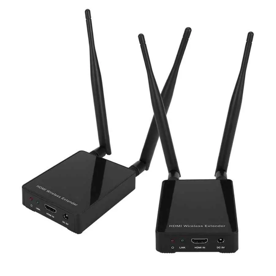
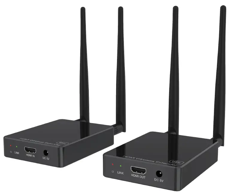
VBESTLIFE HDC-E5100W 100M HDMI Video Wireless Extender Transmitter Receiver Adapter
Thank you for purchasing this product
For optimum performance and safety, please read these instructions carefully before connecting, operating or adjusting this product. Please keep this manual for future reference.
Surge protection device recommended
This product contains sensitive electrical components that may be damaged by electrical spikes, surges, electric shock, lighting strikes, etc. Use of surge protection systems is highly recommended in order to protect and extend the life of your equipment.
Introduction
This product is based on H.265 standard solution for transmitting one HD source signal to one HD display. It extends distance up to 330ft/100 meters (In an open environment without Wi-Fi interference) between the encoder and decoder via wireless transmission. It supports one-way IR control. It offers high quality configurable, low-bandwidth H.265 compression video and supports resolution up to 1080P@60Hz. This wireless extender is designed special to transmit high definition video & audio within one environment.
Features
- HDMI 1.3, HDCP 1.4 and DVI 1.0 compliant
- Transmit one HDMI HD source signal to one HDMI HD display via wireless technology
- With one-way IR control
- Video resolution up to 1080P@60Hz
- HDMI wireless transmission distance up to 330ft/100m. (In an open environment without Wi-Fi interference.)
- Supported audio formats: LPCM 2.0CH 32KHz/44.1KHz/48KHz
- Adopt H.265 high performance codec technology
- End-to-end delay is less than 120Ms
- Compact design for easy and flexible installation.
Package Contents
| Qty | Item |
| 1 | HDMI Wireless Extender (Encoder) |
| 1 | HDMI Wireless Extender (Decoder) |
| 1 | IR Blaster cable (1.5 meters) |
| 1 | 20~60KHz IR Receiver cable (1.5 meters) |
| 4 | 5G WiFi Antenna |
| 2 | 5V/1A Power Adapter |
| 1 | User Manual |
Specifications
| Technical | |
| HDMI Compliance | HDMI 1.3 |
| HDCP Compliance | HDCP 1.4 |
| Video Bandwidth | 6.75Gbps |
| Video Resolution | 1080p, 1080i, 720p, 720i, 480p, 480i, 1920×1080@60Hz,1920×1200@60Hz(Maximum) |
| Color Space | RGB/YCbCr 4:4:4, YCbCr 4:2:2, YUV 4:2:0 |
| Color Depth | 8/10/12-bit (1080P60Hz) |
| HDMI Audio Formats | LPCM 2.0CH 32KHz/44.1KHz/48KHz |
| ESD Protection | Human body model — ±8kV (Air-gap discharge) & ±4kV (Contact discharge) |
| Connection | |
| Encoder | Inputs: 1x HDMI Type A [19-pin female] Outputs: 1x IR OUT [3.5mm Stereo Mini-jack] 2x WiFi OUT [WiFi antenna] Control: 1x SERVICE [Micro USB, Update port] |
| Decoder | Inputs: 1x IR IN [3.5mm Stereo Mini-jack] 2x WiFi IN [WiFi antenna] Outputs: 1x HDMI Type A [19-pin female] Control: 1x SERVICE [Micro USB, Update port] |
| Mechanical | |
| Housing | Plastic Enclosure |
| Color | Black |
| Dimensions | Encoder / Decoder: 76mm [W] x 98mm [D] x 21mm [H] |
| Weight | Encoder / Decoder: 100g |
| Power Supply | Input: AC100 – 240V 50/60Hz Output: DC 5V/1A |
| Power Consumption | Encoder: 2.25W, Decoder: 1.8W |
| Operating Temperature | 32 – 104°F / 0 – 40°C |
| Storage Temperature | -4 – 140°F / -20 – 60°C |
| Relative Humidity | 20 – 90% RH (no condensation) |
| Resolution / Cable Length | 1080P60Hz – Feet / Meters |
| HDMI IN / OUT | 42ft / 15M |
| The use of “Premium High Speed HDMI” cable is highly recommended. | |
Operation Controls and Functions
Encoder Panel
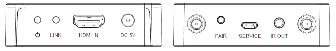
| Name | Function Description |
| Power LED | The LED will illuminate red when the encoder is powered on. |
| LINK LED (Green) | ■ Flicker quickly: The encoder and decoder are pairing. ■ Flicker slowly: The encoder and decoder are transmitting video signal. ■ Illuminate: The encoder is updating firmware. ■ Off: No pairing or no signal transmission after successful pairing. |
| HDMI IN | HDMI source input port for connecting the HDMI source device. |
| DC 5V | Connect the DC 5V/1A power adapter. |
| Antenna port | Connect the WiFi antenna. |
| PAIR button | ■ Short pressing the button will reset the encoder to factory default status. ■ Simultaneously press the PAIR button of the encoder and decoder for 3 seconds to pair. |
| SERVICE port | Firmware update port. |
| IR OUT | Connect the IR blaster cable. The IR blaster signal is from the IR IN port on the Decoder. |
| Antenna port | Connect the WiFi antenna. |
Decoder Panel
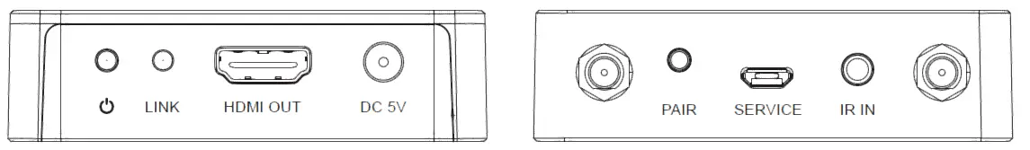
| Name | Function Description |
| Power LED | The LED will illuminate red when the decoder is powered on. |
|
LINK LED (Green) | ■ Flicker quickly: The encoder and decoder are pairing. ■ Flicker slowly: The encoder and decoder are transmitting video signal. ■ Illuminate: Successful pairing, or the decoder is updating firmware. ■ Off: No pairing or no signal transmission after successful pairing. |
| HDMI OUT | HDMI output port for connecting the HDMI display device. |
| DC 5V | Connect the DC 5V/1A power adapter. |
| Antenna port | Connect the WiFi antenna. |
| PAIR button | ■ Short pressing the button will reset the decoder to factory default status. ■ Simultaneously press the PAIR button of the encoder and decoder for 3 seconds to pair. |
| SERVICE port | Firmware update port. |
| IR IN | Connect the IR receiver cable. The IR signal is sent to the IR OUT port on the encoder. |
| Antenna port | Connect the WiFi antenna. |
Pairing Instruction
Power on the encoder and decoder, then simultaneously press their PAIR buttons for three seconds, then LINK LEDs on both of them will flicker quickly. If the LINK LED of the decoder turns to illuminate, but the LINK LED of the encoder still flickers quickly, it indicates successful pairing. Then, release the button, both the LINK LEDs will be off. When there is signal transmission between the encoder and decoder, both the LINK LEDs will flicker slowly.
| Encoder’s LINK LED status (Green) | Decoder’s LINK LED status (Green) | Description |
| Flicker quickly | Flicker quickly | The encoder and decoder are pairing. |
| Flicker quickly | Illuminate | Successful pairing. |
| Off | Off | No pairing or no signal transmission after successful pairing. |
| Flicker slowly | Flicker slowly | The encoder and decoder are transmitting video signal. |
Updating Instruction
Change the name of the update file to be update. bin, then put it in the root directory of U disk. Power off the unit and insert the U disk into the SERVICE port. Press and hold on the PAIR button, and power on the unit simultaneously. If the LINK LED illuminates, it indicates that the unit is updating the firmware, then release the button. After the updating is finished, the LINK LED will be off automatically.
IR Pin Definition
IR Receiver and Blaster pin’s definition is as below: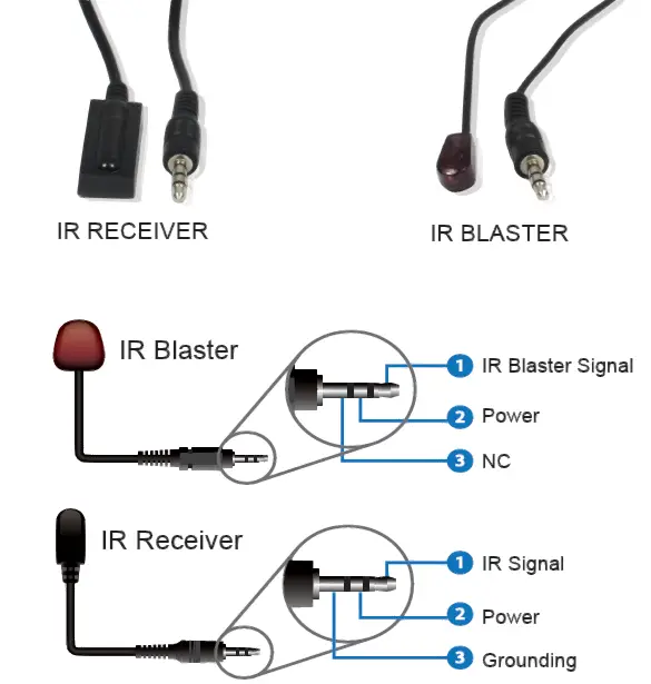
Connection diagram of using IR cables.
TV Note that when the angle between the IR receiver and the remote control is ± 45 °, the transmission distance is 0-5 meters; when the angle between the IR receiver and the remote control is ± 90 °, the transmission distance is 0-8 meters.
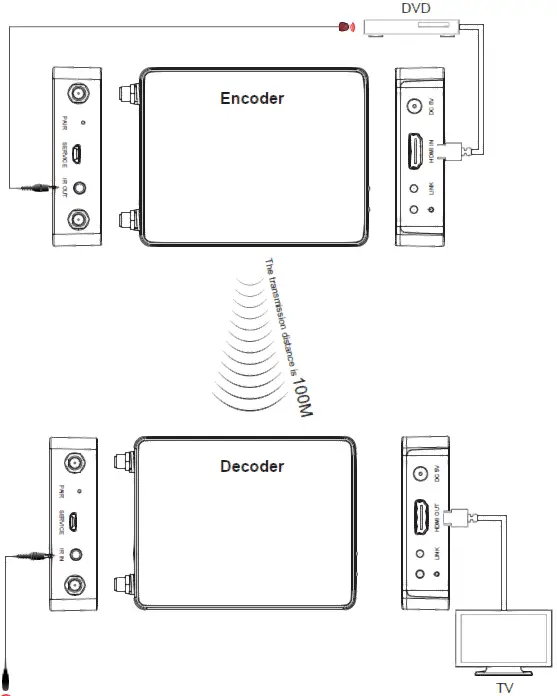
Application Example
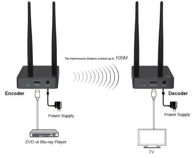
![]()


