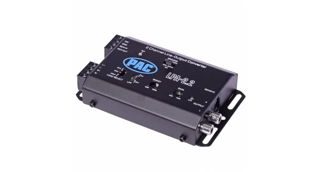
![]() LPA-2.2 2 Channel Line Output Converter
LPA-2.2 2 Channel Line Output Converter
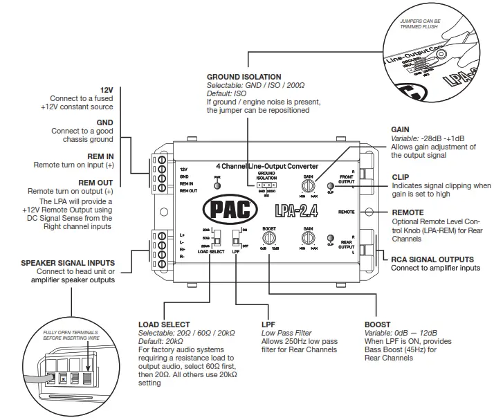
LPA-2.4 4 Channel Line-Output Converter
User Guide
LOG PRO ADVANCED
Line Output Converter
Line Output Converter Gain Level Set-Up
Quick Start Guide
The L.O.C.PRO ADVANCEDTM can be used to add amplifiers to an audio system that does not have RCA outputs or when replacing an OEM radio and retaining the factory amplified system. Variable Gain Controls with Clipping Indicators, Selectable Ground Isolation and Load Select features ensure a pure, noise-free signal for any type of audio system.
This Quick Start Guide will get you going, but if you need additional help or information, please visit our website or contact Technical Support.
Features & Wiring Information
Example Installation
Speaker level input from radio to RCA level output for an aftermarket amplifier is the most commonly used configuration for the L.O.C.PRO ADVANCED. This will create RCA-level outputs from a radio that only has speaker-level outputs.
In the example below, the Positive(+) and Negative(-) wires of two speakers are “tapped” and connected to the SPEAKER SIGNAL INPUTS of the LPA. The speakers will continue to play as normal. The REM OUT is connected to the amplifier’s turn-on. When the radio is turned on the LPA will automatically turn on the amplifier. Lastly, the RCA SIGNAL OUTPUTS from the LPA are connected to the aftermarket amplifiers’ inputs.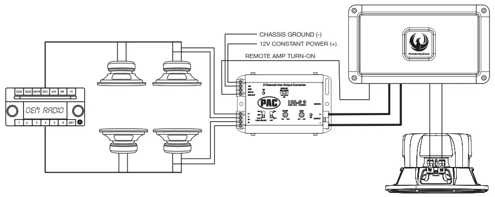
For more installation examples, tech tips, and updates, visit the L.O.C.PRO ADVANCED product pages on PAC-Audio.com

https://catalog.pac-audio.com/catalog/lpa/
Specifications
| Model Number | LPA-2.2 | LPA-2.4 |
| Channels | 2 IN — 2 OUT | 2 IN — 4 OUT |
| Operating Voltage | 9V-16V | 9V-16V |
| Max Input Level (20kHQ Load Setting) | 40V / 400W 0 4 Ohms | 40V / 400W 0 4 Ohms |
| Auto Turn On | DC Offset / Remote | DC Offset / Remote |
| Output Voltage MAX 13.8V | 9.5V RMS | 9.5V RMS |
| Turn On Trigger (DC-Offset) | 3V-7V | 3V-7V |
| Load Input Impedance | 200, 60Q, 20K0 | 20n, 60Q, 201CQ |
| Output Impedance | <1200 | <1200 |
| Variable Gain Adjustment | -28dB—+1dB | -28dB—+1dB |
| Signal To Noise | >110dBA 0 6.4V Output | >110dBA 0 6.4V Output |
| THD+N | <0.01% | <0.01% |
| Input Sensitivity | 0.5V-40V | 0.5V-40V |
| Frequency Response | 10Hz-20kHz | 10Hz-20kHz |
| Current Draw (Max) | 40mA | 40mA |
| Low Pass Filter | <250Hz | <250Hz |
| Bass Boost | 0dB to +12dB | 0dB to +12dB |
| Clip Indicator | YES | YES |
| Remote Level Control | OPTIONAL (PN: LPA-REM) | OPTIONAL (PN: LPA-REM) |
| Chassis Type | Stamped Steel | Stamped Steel |
| Terminal Gauge | 18AWG / Quick Connect | 18AWG / Quick Connect |
Advanced method –
Required items:
- Digital Multi-Meter
- Test track media 0 1kHz and 100Hz. (Download from PAC-Audio website’s LPA section)
- Maximum Amplifier Line-level Input Voltage Specification (i.e., 4vrms, 8vrms, etc.)
Proper level adjustment is crucial for obtaining the best possible sound quality. Following the guidelines below will enable you to properly set the output gain of the LPA using equipment that is readily available.
Amplifiers usually have 4-6v max line-level input ratings but this can vary. This max line-level input will be the target setting you will read on the multi-meter.
Perform the following procedure for each LPA you are installing.
- Start with gain adjustment levels on LPA set to a minimum.
- Set the head unit’s audio setting to the center (flat) position such as Bass, treble, balance, and fader. Turn off any loudness or other signal processing features (preset EQ).
- Turn the source unit to maximum volume and start the test track (1 kHz for mid/high or full range, 100Hz for sub). If Bluetooth is used as the source, make sure the device volume is set to maximum.
- Choose either left or right channel – With multi-meter, test output of LPA front channels. Probe with negative on RCA shield and positive in center of RCA output.
- Slowly adjust the gain level on LPA until you reach the target voltage of the amplifier. Turn down the LPA gain level if the clipping light turns on.
- Repeat steps for rear channels (if connecting to a different amplifier, adjust to that amplifier’s voltage requirements).
- Turn the volume down and system off.
- Connect RCAs, and set gains on amplifiers to a minimum.
- Turn the system on and fine-tune the gain of the amplifier by following the amplifier’s instruction manual.
Example scenarios:
Amplifier 1 (Mid/High frequency) has a maximum 4v input voltage, so you will be targeting a 4-volt output voltage from the LPA. Amplifier 2 (Sub frequency) has a maximum 6v input voltage, so you will be targeting a 6-volt output volt-age from the LPA.
Basic method —
- Start with gain adjustment levels on LPA and amplifiers set to a minimum.
- Turn the head unit to 3/4 maximum volume and play a test track (Random Noise) or a familiar song that has dynamic attributes. For example, if your volume goes to 40 you will turn it up to 30 and play a song that has some quiet sections and some really loud sections.
- Slowly adjust the front channel gain of LPA until just a hint of distortion is audible, and then back down again just under that threshold and the distortion goes away.
- Repeat steps 1-3 for rear channels.
Technical Support
Phone: 727-592-5991
Email: [email protected]
Chat: PAC-Audio.com ©2021
TLPA-GAIN-ADJ 040721


