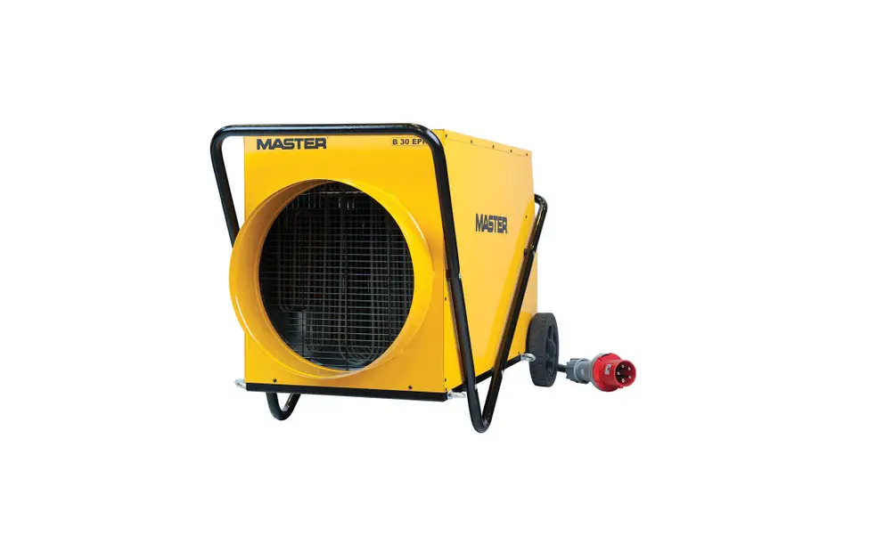
MASTER B 18 EPR 30kW Electric Fan Heater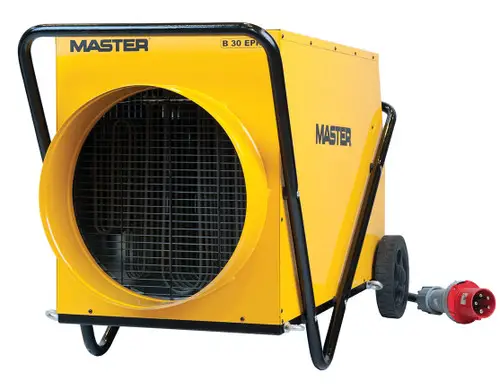
IMPORTANT: CAREFULLY READ THIS SERVICE MANUAL BEFORE YOU START TO USE, REPAIR OR CLEAN THE HEATER. IMPROPER USE OF THE APPLIANCE MAY CAUSE SERIOUS INJURIES, BURNS, ELECTRIC SHOCK OR FIRE.
SAFETY INSTRUCTIONS
The appliance has been designed for heating closed areas such as e.g. warehouses, shops and houses.
![]() WARNING: Do not place the heater directly under the wall outlet. Do not touch internal components of the heater.
WARNING: Do not place the heater directly under the wall outlet. Do not touch internal components of the heater.
This appliance is not intended for use by persons (including children) with reduced physical, sensory or mental capabilities, or lack of experience and knowledge, unless they have been given supervision or instruction concerning use of the appliance by a person responsible for their safety. Children should be supervised to ensure that they do not play with the appliance.
 Do not cover the heater when it is operating. The appliance may get overheated.
- Do not operate the appliance close to humid places such as water tanks, bathtubs, showers or swimming pools. Any contact with water may be the reason of short-circuit or electric shock.
- The heater should be kept at a safe distance from flammable materials. The minimum safety distance should not be inferior to 0.5 m, otherwise you run the risk of starting the fire.
- Do not use the heater in dusty spaces or rooms where gasoline, solvents, paints or other volatile and inflammable materials are stored in order to avoid the risk of explosion.
- The heater should not be used close to the curtains or other textiles in order to avoid the risk of fire.
- Be particularly cautious when using the heater in the rooms frequented by children or animals.
- The heater should be supplied from a source meeting the requirements specified on the rating plate.
- Use only a feeder cable including the earth lead in order to avoid electric shock in emergency situations.
- Do not unplug the heater by pulling the wire out of the wall socket. The appliance should cool down through the ventilation effect.
- Unplug the heater when not used in order to avoid accidental damages.
- Before you dismantle the casing check if the feeder cable has been pulled out of the wall socket. Internal components may be live.
 Do not cover the heater when it is operating. The appliance may get overheated.
UNPACKING AND TRANSPORT
- Open the package and take the heater out including all the safety locks installed for the period of transport.
- Should the appliance seem damaged, notify immediately the seller of the same.
- Transport the heater using the lifting eyes No. 1 shown in Fig. 1.

- The heater should be transported in original package including the safety locks.
DESCRIPTION OF INDIVIDUAL COMPONENTS
See Fig. 1-2: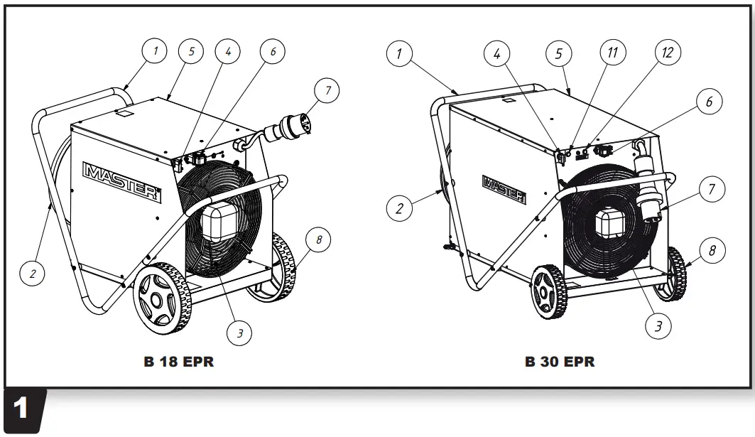
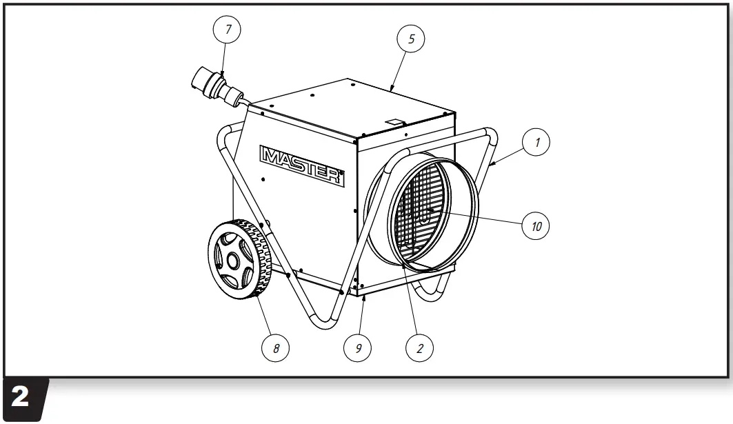
- Handle
- Tuba air outlet
- Motor with fan
- Switch
- Casing
- Thermostat external socked
- Plug
- Wheel
- Base foot
- Heating element
- Signal light

- Signal light RESET
SWITCHING ON
![]() WARNING: Carefully read this service manual before you start to use the heater. The instructions contained herein will allow you to use the appliance in a safe manner.
WARNING: Carefully read this service manual before you start to use the heater. The instructions contained herein will allow you to use the appliance in a safe manner.
Make sure the power supply cable has not been damaged.
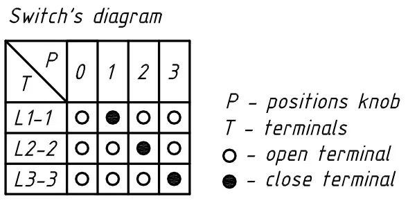
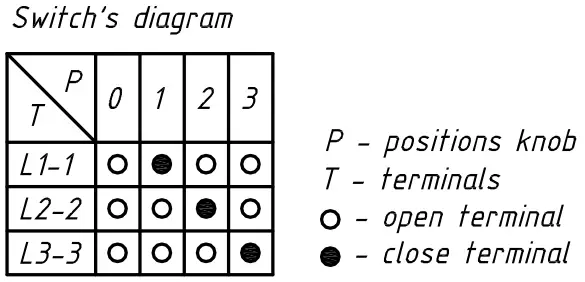
If the supply cord is damaged, it must be replaced by the manufacturer, its service agent or similarly qualified persons in order to avoid a hazard. Moreover, check if the technical parameters of power supply source comply with the requirements specified on the rating plate. Place the appliance in its upright position. Make sure the switch is in its ”0” position shown in Fig. 3. Connect the heater to the power supply source. Turn the switch and leave it for 5 seconds in the positions as follows: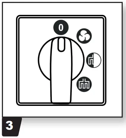
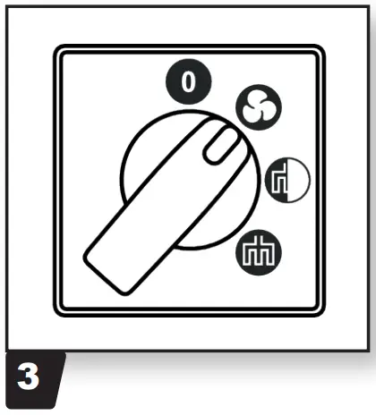
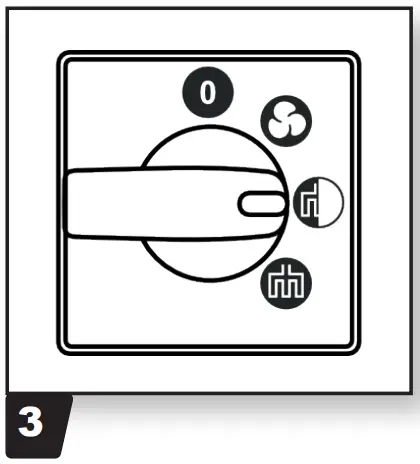
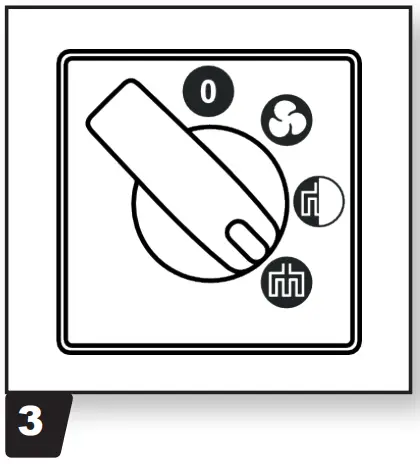
- Fan only: Fig. 3;
- 1st degree of heating: Fig. 3, and
- 2nd degree of heating: Fig. 3.
SWITCHING OFF
Turn the switch to its ”0” position. Once the heating is off, leave the fan operating for 3 minutes.
WORK WITH THE HOSE DISTRIBUTING HOT AIR (FIG. 7)
The appliance is adapted to work with a hot air hose distributor up 100oC. The hose distributing hot air of Ø305 mm (B 18 EPR) / Ø407 mm (B 30 EPR) and max 15m length shold be connected to the outlet. After connection make sure that the hose is patent and not folded to let the air flow property.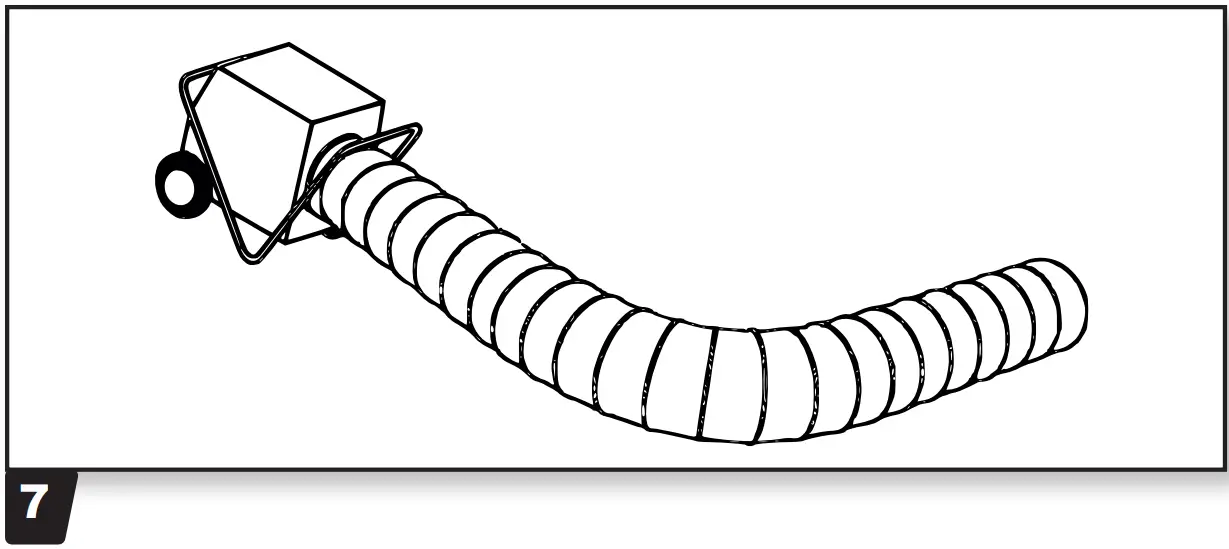
THERMAL CIRCUIT BREAKER “RESET”
The appliance has been equipped with an integrated thermal circuit breaker ensuring high safety level. The breaker will automatically switch the power supply off once a limit temperature is exceeded. Should it happen, let the appliance cool down and only then, look for the reason of the problem. Next push the ”RESET” button (Fig. 4) with a pointed tip in order to unlock the thermal circuit breaker. If the heater does not operate, contact the seller or approved service centre.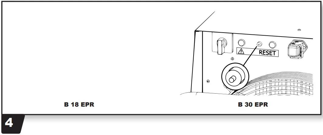
OUT OF SEASON STORAGE
Should the appliance remain idle for a long period of time, clean it before shoving by blowing the inside with compressed air. The heater should be kept in a dry and clean place.
Before you start using it again make sure the power supply cable has not been damaged. In the case of any doubts contact the seller or approved service centre.
FUNCTIONAL INSPECTION
The appliance should be checked at least once a year by competent service personnel approved by the manufacturer.
Any inspections or repairs should be conducted by competent personnel only.
EXTERNAL THERMOSTAT
The appliance may work with external thermostat.
Heating without room termostat
The unit runs under continuous duty
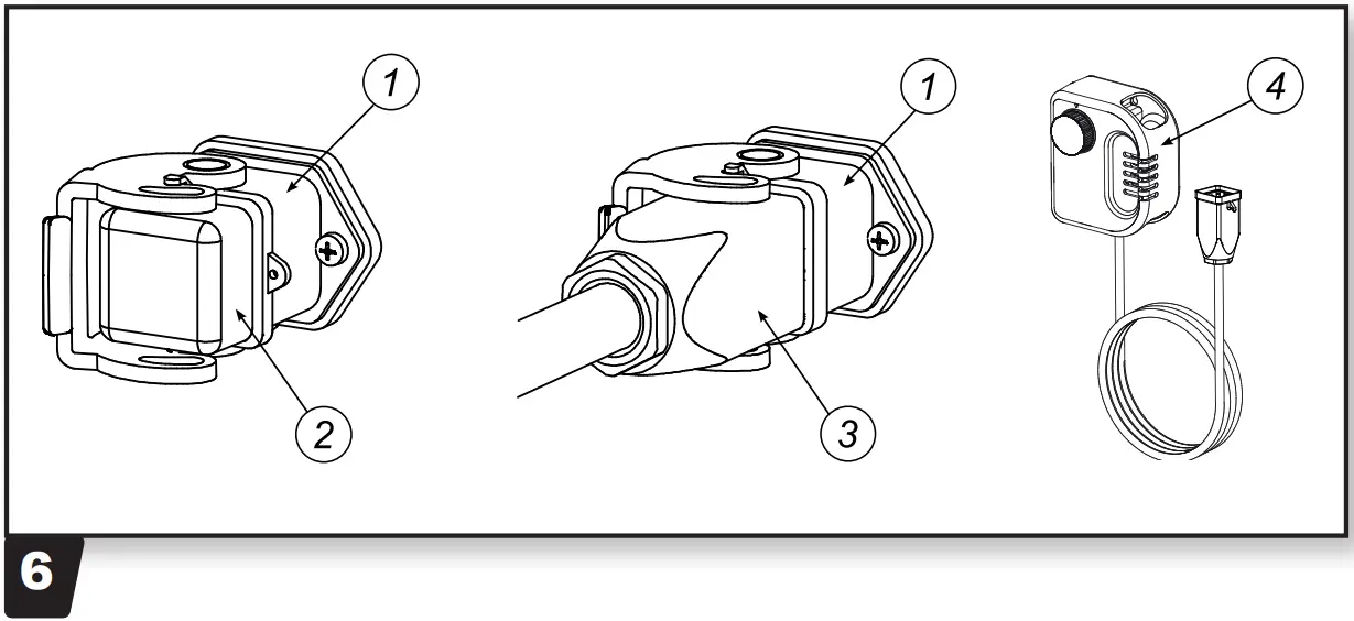
- Connect the supplied bridge circuit plug 2 Fig. 6 to the thermostat socket 1 Fig. 6 of the unit.

- Put the switches into the desired position
- WARNING: For optimum unit operation, the device should not be operated at an ambient temperature above 25°C.
Heating with room thermostat
The unit runs fully automatically and is dependent on set temperatures.
- Remove the bridge circuit plug 2 Fig. 6
- Connect thermostat plug 3 fig 6 of the room thermostat (accessories) to the thermostat socked 1. Fig. 6
- Put room thermostat 4 Fig. 6 in a suitable place. The thermostat sensor may not be exposed directly to the hot air current and not fixed directly on a cold surface.
- Pre-select desired room temperture on the room thermostat.
- Put the switches (Fig. 3) into the desired position.
TROUBLESHOOTING
| PROBLEM | REASON | SOLUTION |
| The motor operates while the appliance does not heat | Thermal circuit breaker is active Thermostat has been damaged Relay has been damaged Heating element has been damaged | Let the heater cool down and push the “RESET” button Replace the thermostat Replace the relay Replace the heating element |
| The motor does not operate while the heating elements are hot | Motor has been damaged Fan has been stopped Switch has been damaged | Replace the motor Unlock / clean the fan Replace the switch |
| The whole appliance does not operate | Electric circuit open Switch has been damaged | Check power supply connection Replace the switch |
| Reduced air flow | Foul air duct Motor has been damaged | Open the air duct Replace the motor |
WIRING DIAGRAM
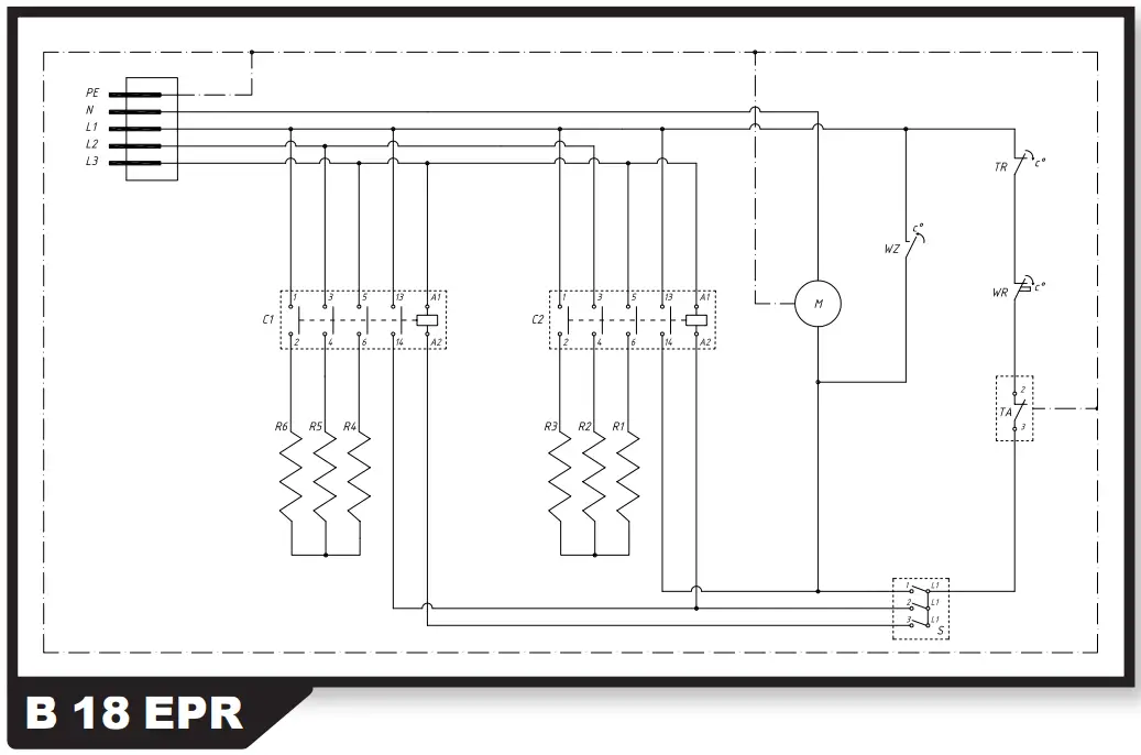
- S – rotary switch
- M – motor
- TR – automatical thermal cut-out
- WR – thermal cut out with manual reset
- WZ – fan thermostat
- TA – ambient thermostat socket
- C… – contactor
- R… – heating element
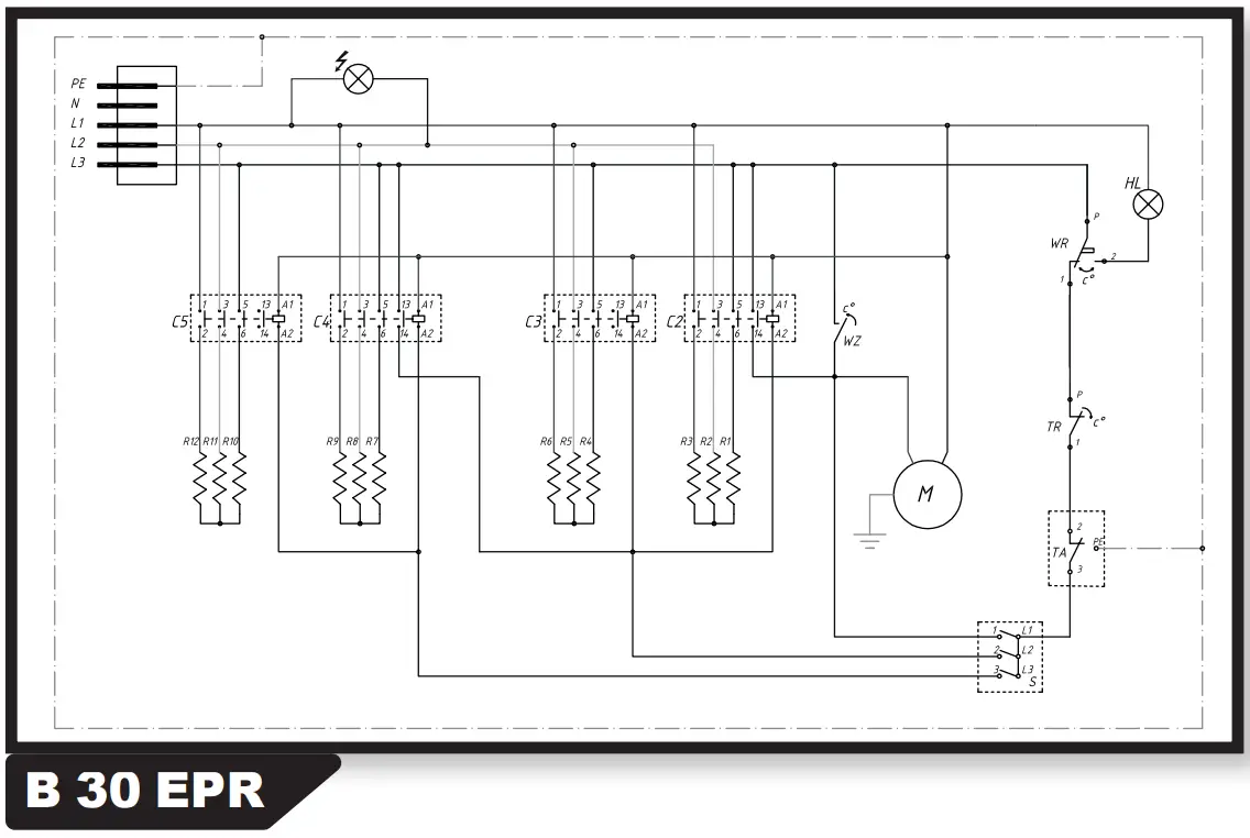
- S – rotary switch
- M – motor
- TR – automatical thermal cut-out
- WR – thermal cut out with manual reset
- WZ – fan thermostat
- TA – ambient thermostat socket
- C… – contactor
- R… – heating element
- HL – overheat led
CE CONFORMITY CERTIFICATE

DANTHERM S.p.A. Via Gardesana 11, -37010- Pastrengo (VR), ITALY
Product B 18 EPR – B 30 EPR
We declare that it is compliant with: 2014/30/EU, 2014/35/EU, 2009/125/EC
EN 62233:2008, EN 61000-3-2:2014, EN 61000-3-3:2013, EN 55014-1:2006/A2:2011, EN 55014-2:2015, EN 60335-2-30:2009/A11:2012, (EU) N°. 1188/2015
Pastrengo, 2022

Stefano Verani (Member of the Board)
UKCA CONFORMITY CERTIFICATE

DANTHERM S.p.A. Via Gardesana 11, -37010- Pastrengo (VR), ITALY
Product B 18 EPR – B 30 EPR
We declare that it is compliant with:
2014/30/EU, 2014/35/EU, 2009/125/EC
BS EN 62233:2008, BS EN 61000-3-2:2014, BS EN 61000-3-3:2013, BS
EN 55014-1:2017+A11:2020, BS EN 55014-2:2015, BS EN 60335-2-
30:2009+A11:2012
Pastrengo, 2022

Stefano Verani (Member of the Board)
TECHNICAL DATA
| MODEL | B 18 EPR | B 30 EPR | |
| Power | kW | 9 – 18 | 15-30 |
Switch | kW | FAN | FAN |
Switch | kW | 9 | 15 |
Switch | kW | 18 | 30 |
| Max current cons. | A | 26 | 43,5 |
| Voltage | V/Hz | 380-400 50 | 380-400 50 |
| Air displacement | m3/h | 1700 | 3500 |
| Weight | kg | 27,5 | 53 |
| Dimension L x W x H | cm | 69x46x55 | 102x58x67 |
| Resistance norm | IP24 | IP24 | |
| MODEL | B 18 EPR | B 30 EPR | ||
| SYMBOL | UNIT | |||
| HEAT OUTPUT | ||||
| Nominal heat output | Pnom | kW | 18 | 30 |
| Minimum heat output (indicative) | Pmin | kW | 9 | 15 |
| Maximum continuous heat output | Pmax,c | kW | 18 | 30 |
| AUXILIARY ELECTRICITY CONSUMPTION | ||||
| At nominal heat output | elmax | kW | N/A | N/A |
| At minimum heat output | elmin | kW | N/A | N/A |
| In standby mode | elSB | kW | N/A | N/A |
| TYPE OF HEAT INPUT, FOR ELECTRIC STORAGE LOCAL SPACE HEATERS ONLY (SELECT ONE) | ||||
| Manual heat charge control, with integrated thermostat | No | |||
| Manual heat charge control with room and/or outdoor temperature feedback | No | |||
| Electronic heat charge control with room and/or outdoor temperature feedback | No | |||
| Fan assisted heat output | No | |||
| TYPE OF HEAT OUTPUT/ROOM TEMPERATURE CONTROL (SELECT ONE) | ||||
| Single stage heat output and no room temperature control | No | |||
| Two or more manual stages, no room temperature control | No | |||
| With mechanic thermostat room temperature control | Yes | |||
| With electronic room temperature control | No | |||
| Electronic room temperature control plus day timer | No | |||
| Electronic room temperature control plus week timer | No | |||
| OTHER CONTROL OPTIONS (MULTIPLE SELECTIONS POSSIBLE) | ||||
| Room temperature control, with presence detection | No | |||
| Room temperature control, with open window detection | No | |||
| With distance control option | No | |||
| With adaptive start control | No | |||
| With working time limitation | No | |||
| With black bulb sensor | No | |||
| Conctact Details (See the CE CONFORMITY CERTIFICATE) | ||||
ATTENTION: This product is only suitable for well insulated spaces or occasional use
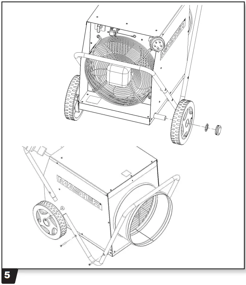
FIRST ASSEMBLY OF THE HEATER
DISPOSAL OF THE PRODUCT
- This product has been designed and manufactured with top-quality materials and components, which can be re-cycled and re-used.
- When a crossed-wheely bin symbol is attached to the product, it means that the product is protected by the, 2012/19/UE European Directive.
- Please obtain information regarding the local differentiated collection system for electrical and electronic products.
- Respect local Standards in force and do not dispose of old products as normal domestic waste. Correct disposal of the product helps to prevent possible negative consequences for health, the environment and mankind.
CUSTOMER SERVICE
Dantherm A/S
Marienlystvej 65 DK-7800 Skive Denmark
t. +45 96 14 37 00
Dantherm Sp. z o.o. ul.
Magazynowa 5a 62-023 &Oki Poland
t. +48 61 65 44 000
Dantherm AB
Fridhemsvagen 3 602 13 Norrkoping Sweden
t. +46 (0)11 19 30 40
Heylo GmbH Im
Finigen 9 28832 Achim Germany
t. +49 4202 97550
Dantherm Ltd. Unit 12,
Galliford Road Maldon CM9 4XD United Kingdom
t. +44 (0)1621 856611
Dantherm SP S.A.
C/Calabozos 6 (Poligono Industrial) 28108 Alcobendas, Madrid Spain
t. +34 91 661 45 00
Dantherm LLC
Transportnaya 22/2 142800, Stupino Moscow Russia
t. +7 (495) 642 444 8
SET Energietechnik GmbH
August-Blessing-Stralle 5 71282 Hemmingen Germany
t. +49 7150 94540
Dantherm GmbH
Oststralle 148 22844 Norderstedt Germany
t. +49 40 526 8790
Dantherm SAS 23 rue
Eugene Henaff 69694 Venissieux Cedex France
t. +33 4 78 47 11 11
MCS China Unit 2B,
No. 512 Yunchuan Road Baoshang, Shanghai, 201906 China
t. +8621 61486668


