Enerdrive EN-LBC1224-40-G2 Low Battery Cut-Out
Description
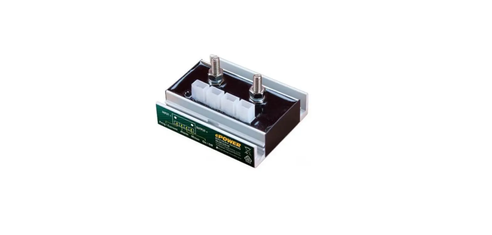
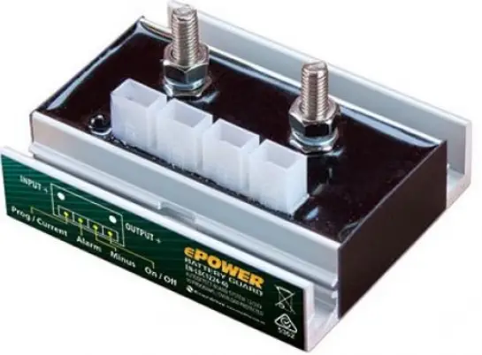
The Low Battery Cut-out; EN-LBC1224-40-G2 & EN-LBC1224-60-G2 (hereafter referred to as the LBC) is an intelligent, user-programmable, fully waterproof unit. The LBC has expansion options for an off-switch and an alarm output to which a buzzer, LED strip or relay can be connected. To minimise losses, the LBC is equipped with 2 bolt-on connections: input+ and output+. The remaining connections (neg, remote input, programmable input and alarm output) are connected via separate 6.3mm faston connectors. The LBC is equipped with a bright status LED which displays how it is functioning. The LBC also features an “automatic board system detection”, which enables it to automatically detect whether it is connected to a 12V or a 24V system.
Installation
Install the LBC in a cool space to allow for maximum heat dissipation. Use a power supply cable of up to 50cm for the LBC. This is the only way to accurately monitor the system’s battery voltage.
PLEASE NOTE
- The product may only be installed by someone who is qualified and fully aware of the requirements for working with batteries.
- The use of faulty connection material and/or excessively high gauge wiring may damage the LBC.
- A short circuit between the battery’s positive and negative terminals can cause serious damage to the system.
- Always use the correct fuses.
- Use at least 1.5mm² cable directly from the battery to the LBC for the negative (-) connection. Do not use this connection for anything else.

Operation
Input Voltage Operation
The input voltage protection values (undervoltage threshold, undervoltage reset, overvoltage threshold and overvoltage reset) can be set by the user. See Programming for an explanation of how to set these values.
Undervoltage
When the LBC input voltage drops below the average threshold for 15 seconds, the alarm output will turn on. The LED will also indicate Undervoltage. The LBC will shut down one minute later and the alarm output and LED will turn off. When the LBC input voltage exceeds the reset threshold for 5 seconds, the LBC will turn back on, and the LED will indicate that the LBC is active again.
Overvoltage
The LBC will shut down if the input voltage exceeds the overvoltage threshold for 0.5 seconds. The alarm output will indicate (at a frequency of 1 Hz) that overvoltage has been detected. The LED will also display this information.
Overcurrent Protection
The current through the LBC is measured constantly. If an excessive current flows through the LBC for too long, the LBC will shut down to prevent damage to both the LBC and the connected equipment. The LBC will turn on again after 1 minute.
Temperature Protection
The LBC will shut down immediately if its temperature exceeds 85°C. The LED will indicate a fault. The LBC will turn on again after 1 minute if the temperature has dropped below 75°C.
Ground Loss Protection
The LBC will shut down if it detects that the negative (-) is disconnected on the power supply side. The LED will indicate a fault. The LBC will turn on again after 1 minute.
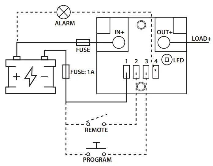
Remote
A switch can be installed between the remote input and the negative (-) to manually disable the LBC output. The LBC will shut down immediately when the connection is made. The LBC will turn on again when the connection is broken.
LED
The LED has 2 functions. The first is to indicate the LBC’s status. The different options are outlined below. The second is to program the LBC. This operation is described in the section “Programming”.
| LED Code |
| 2 short blinks (± 0.15 sec) then off for a long time (± 3.5 sec). |
| 1 blink (± 0.5 sec), then off (± 1.5 sec). |
| 1 blink (±1.0 sec), then off (± 1.0 sec). |
| 3 short blinks (± 0.25 sec), then off for a long time (± 2.5 sec). |
| LED is off. |
| Fault Description |
| LBC is enabled. |
| LBC is disabled because the remote has been activated. |
| Undervoltage or overvoltage detected. |
| LBC has been shut down for 1 minute due to one of the following causes: Ground loss, temperature protection, current protection, low output voltage. |
| LBC has been shut down due to undervoltage. |
Programming
To enter programming mode, a connection must be made between the program input and the negative (-). The LED will blink once if the connection has been maintained for ± 2 seconds. Once this is done, the connection must be broken. The same connection must be made briefly again to set the correct position number – the LED will light up as feedback. At that point, program position #1 is selected. The user can briefly make the connection again to select program position #2, etc. If no connection is made for ± 4 seconds, the LED will display the set state again. (Eg. program position #4 is set by a user, the LED will blink 4 times). 2 types of settings are available. Positions 1 through 10 set the undervoltage threshold and reset values. Positions 11 & 12 set the overvoltage threshold and reset values. These settings must be selected individually. The programmed positions are retained when the battery voltage is disconnected.
Technical Data
| ELECTRICAL | EN-LBC1224-40-G2 | EN-LBC1224-60-G2 |
| Input Voltage Range | 6 – 35VDC | |
| Maximum continuous output current (@25°C) | 40A | 60A |
| Peak Current (@25°C) | 300A (± 0.7 sec) | |
| Voltage Drop | 40 mV @ 40A 60 mV @ 60A | |
| Current Consumption – Output Active | 3.2 mA | |
| Current Consumption – Output Inactive | 3.2 mA | |
| Voltage Accuracy | 2% | |
| Current Accuracy | 10% | |
| Maximum Alarm Output Load | 100 mA | |
| INPUT & OUTPUT CONNECTION | EN-LBC1224-40-G2 | EN-LBC1224-60-G2 |
| Minimum Conductor Guage | 10 mm² | 16 mm² |
| Bolt Size | M6 | |
| Cable Lugs | Cable Lugs must match the cable diameter used | |
| FASTON CONNECTIONS | EN-LBC1224-40-G2 | EN-LBC1224-60-G2 |
| Minimum Conductor Guage | 1.5 mm² | |
| Faston Plug | 6.3 mm | |
| MECHANICAL | EN-LBC1224-40-G2 | EN-LBC1224-60-G2 |
| Mounting Hole (Ø) | 4.2mm | |
| Distance Between Mounting Holes (centre to centre) | 50.5mm | |
| Weight | 155.4g | |
| Dimensions (H x L x W) | 72 x 32 x 62.2mm | |
| IP Code | IP66 | |
| Housing Material | PU552 | |
| Housing Colour | Black | |
| Cooling Concept | Convection and Conduction | |
| INPUT & OUTPUT CONNECTION | EN-LBC1224-40-G2 | EN-LBC1224-60-G2 |
| Operational Ambient Temperature | -10°C ~ +40°C | |
| Storage Temperature | -25°C ~ +85°C | |
| Operational Air Humidity | Up to 95%, non-condensing | |
| Galvanic Insulation | No | |
| Remote Contact Switch-Of | Yes | |
| PROTECTION | EN-LBC1224-40-G2 | EN-LBC1224-60-G2 |
| Overcurrent / Short Circuit | Yes (after 1 minute restart) | |
| Overheating / Shut-Down | Above 85°C (after 1 minute restart) | |
| Polarity Protection | Yes, with fuse in the negative (-) line | |
Programming Table
| Position | 12V | 24V | ||
| Undervoltage | ||||
| Threshold | Reset | Threshold | Reset | |
| 1* | 10.5 | 12 | 21 | 24 |
| 2 | 10 | 11.5 | 20 | 23 |
| 3 | 9.5 | 11.5 | 19 | 23 |
| 4 | 11.25 | 13.25 | 22.5 | 26.5 |
| 5 | 11.5 | 13.8 | 23 | 27.6 |
| 6 | 10.5 | 12.8 | 21 | 25.6 |
| 7 | 11.5 | 12.8 | 23 | 25.6 |
| 8 | 11.8 | 12.8 | 23.6 | 25.6 |
| 9 | 12 | 13 | 24 | 26 |
| 10 | 12.5 | 13.2 | 25 | 26.4 |
| Position | Overvoltage | |||
| Threshold | Reset | Threshold | Reset | |
| 11* | 16 | 15.8 | 32 | 31.6 |
| 12 | 15.4 | 15.2 | 30.8 | 31.4 |
- [email protected]
- Ph: 1300 851 535
- www.enerdrive.com.au


