
![]() Clip CH50 Series Thermal Imaging Attachment
Clip CH50 Series Thermal Imaging Attachment
User Manual
Description
Clip CH50 Series is a multifunctional thermal imager device equipped with two kinds of eyepiece that can be used either as a monocular or a front attachment as the infrared expansion device of day light. Different from the night vision device based on image enhancement, Clip CH50 Series doesn’t need an external light source and isn’t influenced by strong light exposure. It can be used in the night or in bad weather conditions such as fog, rain, smog and can detect objects through obstacles such as branches, tall grass, dense bushes and so on. Clip CH50 Series has a wide range applications including night hunting, observation, terrain orientation, and search and rescue operations. 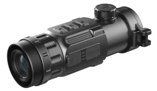
Fig. 1-1 Clip CH50 Series thermal imaging attachment
Components and Controls
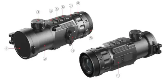
Fig. 2-1 Function introduction
| No. | Name | Function description |
| 1 | Lens Cap | Protecting the lens and using it for background correction |
| 2 | Objective Lens | Power on/Power off/Standby/Up/Left |
| Entering menu/Parameter switch | ||
| 3 | Lens Focus knob | Used to adjust the focal length of the objective lens to make the image to be the clearest when the image is indistinct. |
| 4 | Power(P) Button | Power on/Power off/Standby/Up/Left |
| 5 | Menu(M) Button | Entering menu/Parameter switch |
| 6 | Correction(C) Button | Shutter correction/Background correction /Down/Right |
| 7 | Locking Ring of Attachment’s Eyepiece | Locking the Attachment’s eyepiece to the Clip C unit. |
| 8 | Bayonet-type ring of attachment’s eyepiece | Used to lock the adapter ring between the daylight sight and the attachment |
| 9 | Attachment’s Eyepiece | Eyepiece as the infrared expansion attachment of daylight sight |
| 10 | Battery Compartment Cover | Use two batteries which are CR123, CR123A, or 16340 to supply power. |
| 11 | Type-C Interface | Used for data communication and external power supply |
Controls
| Operation in normal display mode | Operation in menu mode/calibration interface | ||||
| Short Press | Long Press | Short Press | Long Press | ||
| P (4) Button | Standby/ Awaken | Power on / Power off | P (4) Button | Adjust parameter /Scroll up options | |
| M (5) Button | Enter the Menu Navigation | Enter the advanced menu | M (5) Button | Function switch/Parameter selection | Save and exit menu |
| C (6) Button | Shutter Calibration | Background Calibration | C (6) Button | Adjust parameter/Scroll down options | |
| M (5) Button + P (4) Button | Monocular: Enter the stadiametric rangefinder interface | P (4) Button | Increase the distance between measurement bars | Quickly zoom in | |
| M (5) Button | Exit | ||||
| C (6) Button | Reduce the distance between measurement bars | Quickly zoom out | |||
| P (4) Button + C (6) Button | Enter the compass calibration interface | ||||
| Screen lightness setup–four levels | |
| Image mode: B (Black hot), W (White hot), R (Red hot), C (PseudoColor) | |
| Image Sharpness: levels 1-4 | |
| E-zoom (Only for Monocular: ×1, ×2, ×4) | |
| Ultraclear mode | |
| Bluetooth option | |
| Bluetooth connected | |
| Video output option | |
| Video output on | |
| Battery type selection | |
| Reticle type, four customized sorts | |
| Image calibration | |
| E-Zoom center adjustment | |
| Bad pixel correction option | |
| Factory reset | |
| Battery capacity indicator | |
| Type-C power supply | |
| Orientation shift |
Specifications
| Model | Clip CH50 |
| Detector Parameters | |
| Detector Type | VOx Uncooled |
| Resolution | 640*512 |
| Pixel Size | 12um |
| NETD | ≤40mk |
| Frame Rate | 50Hz |
| Optics Parameters | |
| Objective Lens | 50mm |
| Field of View | 8.8°×7.0° |
| Magnification | Attachment: 1× |
| Diopter Adjustment | -5D~+5D |
| Detection Range (Target size: 1.7m×0.5m, P(n)=99%) | 2597 |
| Display Parameters | |
| Type | OLED |
| Resolution | 1024×768 |
| Electrical Parameters | |
| Battery | CR123×2 |
| Power Consumption | <1200mW |
| Max. Battery Life | 4hr |
| External Interface | |
| USB Interface | Type-C |
| Video Output | PAL (RCA Port) |
| External Power | Type-C |
| Functions | |
| Digital Compass | √ |
| Motion Sensor | √ |
| Remote Control | Bluetooth |
| Physic Parameters | |
| IP Rating | IP66 |
| Weight (without batteries) | <510g |
| Dimension | 167mm×74mm×68mm |
| Adapter Ring | M52×0.75 |
System Function
- Detection range beyond 2.5km
- 1024×768 high resolution OLED display
- Bluetooth remote control
- Four image modes – white hot, black hot, red hot, pseudo color
- Monocular digital zoom:×1 , ×2 , ×4
- Type-C interface power supply and data transmission
- PAL analog video output
- Build-in compass, motion sensor
- IP66 protection level
- Compact size
- Lightweight and great impact resistance
Operation System
Power on / Power off
Press and hold down the P (4) button for 3s to start up the device, the image appears on the display screen. After 6s, the device is turned on.
Press and hold down the P (4) button for about five seconds to shut down the device.
Standby Mode
Enter/exit the standby mode by pressing the P (4) button briefly for power saving.
Status bar
The status bar is located at the bottom of the screen, which shows information such as image mode, screen brightness, E-Zoom, Reticle types, Sharpness, Bluetooth (on), ultra-clear mode (on), video out (on), battery status.
Navigation Menu
In the normal display interface, press M (5) button briefly to switch in the order of “none menu – screen brightness – image mode – sharpness – E-zoom – exit the navigation menu”. And press P (4) button and the C (6) key to adjust the parameters of each function.
The Navigation menu interface is as shown in fig. 6-1. 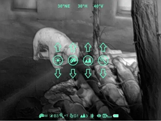
- Screen brightness:1~4 brightness level.
- Image mode: W (White hot), B (Black hot), R (Red hot), C (pseudocolor).
- Image sharpness: 1-4 levels of sharpness.
- E-zoom (only for monocular): ×1 /×2 /×3 /×4.
Advanced Menu
Press and hold down the M (5) button for three seconds to enter the advanced menu interface (fig. 6-2). The six functional options from top to bottom are Ultraclear mode, Bluetooth, video out, reticle type, battery type, Image calibration, E-Zoom center adjust, bad pixel correction, and factory reset. Please refer to Tables 6-1 for details. 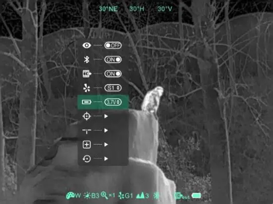
Operations:
- In the advanced menu, press M (5) button briefly to adjust the parameters of the present option or enter the secondary menu.
- P (4) button is used to shift up or left. C (6) button is used to shift down or right;
- Press and hold down M (5) button for three seconds to exit the advanced menu interface.
Table 6-1 Advanced menu function description
Icon | Name | Function | Description | Status |
| Ultraclear Mode | Conversion of normal mode and Ultraclear mode | In this mode, the image contrast is enhanced, which is suitable for cloudy, rainy, foggy and other harsh weather conditions | The icon displays at the status bar. | |
| Bluetooth | ON/OFF | When Bluetooth is on, it can be operated with the Bluetooth remote controller or mobile phone APP (please search for connection by mobile phone within 1 minute, otherwise, the Bluetooth will be automatically turned off ). | The icon displayed at the status bar. | |
| Video Output | ON/OFF | Transfer the analog video in PAL through the Type-C data cable. | The icon is displayed at the status bar. | |
| Battery Type | 3V/3.7V | Select 3V or 3.7V depending on the voltage of the battery | The icon displayed at the status bar. | |
| Zeroing Type | G1/G2/G3/G4 | Up to four groups of calibration data can be stored | The icon displayed at the status bar. | |
| Image Calibration | Enter image calibration interface | Shifting infrared images, ensure daylight & infrared images are in the same location | Image Calibration interface (fig. 6-3) | |
| E- Zoom center adjust | Enter E-700111 center adjust interface | Shifting the center of E-Zoom to ensure the center of E-zoom aligns with the daylight scope’s reticle | E-zoom center adjust interface (fig. 6-4) | |
| Bad Pixel Correction | Calibrate the bad pixels on the image | Refer to 6.8 | Bad pixel calibration interface (fig. 6-5) |
Image Calibration
When the device is installed on the daylight sight as an infrared extension component, if the reticle of the white light sight is not in the center of the infrared image, the image calibration function can be used to shift the infrared image to ensure the position consistency between the white light image and an infrared image.
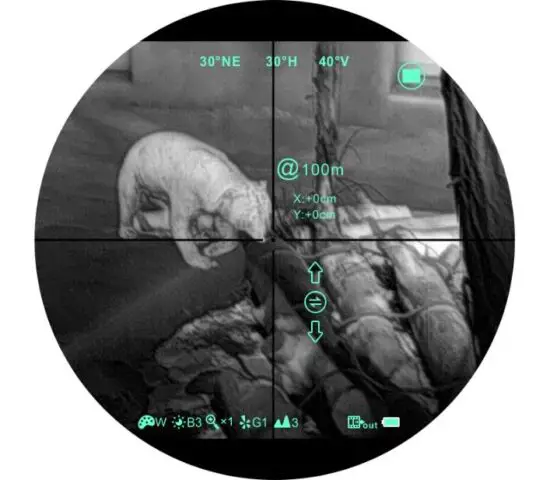 Fig. 6-3 Image calibration interface
Operation:
- Please calibrate the daylight sight before mounting Clip CH50.
- Installing Clip CH50 on the daylight sight and repeat the calibration steps above.
Then aim at the target at 100 meters and shoot. Measure the horizontal distance and vertical distance between the bullet hitting point and the aiming point afterward. - In normal display mode, press and hold down M (5) button to enter the image calibration interface. Pressing the P (4) button or C (6) button briefly to move the position of the infrared image and long press to achieve a quick shift. Pressing M (5) button to switch the orientation of the X-axis (left-right) and Y-axis (up-down) while the moving distance is displayed synchronously above the icon. (as shown in figures 6-3)
- When the calibration is done, long-press M (5) button to save and exit the calibration interface.
Note: Before zeroing function performs, please confirm the storage location, i.e., selection of the type of zero. (Refer to 6.5 for details)
E-Zoom center adjustment
- Please calibrate the image before adjusting the E-zoom center.
- Hold down M (5) button to enter the advanced menu, and select the E-zoom center adjusts option to enter the menu.
- In the adjustment menu, move the white reticle until it overlaps with the daylight scope’s reticle.
- Hold down M (5) button to save and exit the adjustment interface. Aim the target with E-Zoom, and observe if the center of E-zoom overlaps with the reticle of daylight scope. Repeat previous center adjustment if there is deviation.
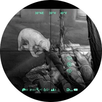 Fig. 6-4 E-zoom center adjustment
Bad Pixel Calibration
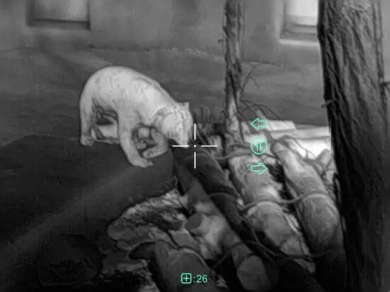 Fig. 6-5 Bad pixel correction interface
- When entering the advanced menu, select the bad pixel calibration option and press M (5) button briefly to enter the bad pixel calibration interface (fig.6-5). A reticle will appear in the center of the screen.
- Then, move the reticle up-down or left-right to select the bad pixel by pressing the P (4) button and C (6) button. Press M (5) button briefly to switch the orientation of X-axis (left-right) and Y-axis (up-down).
- After selecting the bad pixel, press the P (4) and C (6) buttons at the same time to calibrate the bad pixels.
- Repeat the above operations to continue selecting bad pixels, and the status bar at the bottom of the screen will display the number of calibrated bad pixels.
- When the calibration is done, press and hold M (5) button to exit the bad pixel correction.
Compass Calibration
- In the home screen, press and hold the P (4) and C (6) buttons at the same time to enter the compass calibration interface.
- An icon like a triaxial coordinate system appears on the screen (shown as fig. 6-6).
- Follow the icon prompt to rotate the riflescope along three axes at least 360 degrees on each axis in 15 seconds.
- It will automatically exit and complete compass calibration after 15s.
- During the calibration process, press P (4) button briefly to exit the compass calibration interface at any time.
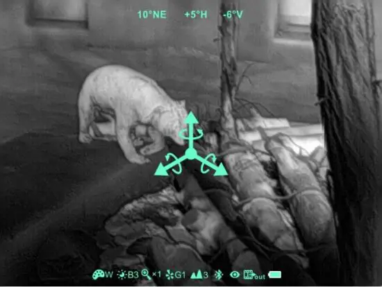 Fig. 6-6 Compass calibration interface
Stadiametric Rangefinder (Only for Monocular)
Stadiametric rangefinder is only for a monocular mode that can estimate the approximate distance to an object of known size. 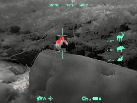
- In the home screen, press and hold the P (4) and C (6) buttons for 3s at the same time to enter the stadiametric rangefinder interface (fig. 6-7).
- The display will show two horizontal lines for measurement, the icons, and the numbers of the measured distance for three objects on the right.
- There are three predefined values for objects:
– Deer – height 1.7m
– Boar – height 0.7m
– Hare – height 0.3m - Locate the target by pressing the P (4) button or C (6) button until the target matches entirely between the two measurement lines. P (4) button is used to increase the distance and C (6) button to reduce the distance.
- The distance to the target is automatically recalculated while moving the measurement lines and displayed on the left of the three reference objects.
- The center and color of the measurement lines is the same as the reticle.
- Exit the rangefinder mode with a long press of the M (5) button.
Accessory Equipment: Remote control/ Mobile App
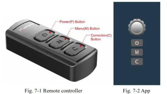
Clip CH50 is equipped with external devices that can be connected via Bluetooth. The button layout of the Bluetooth remote controller and mobile phone APP is consistent with the device, including the Power button, menu button, and correction button. The functions and operation methods are also corresponding to the device. (Refer to figure 7-1 and 7-2 for details)
Bluetooth Remote Controller
- Turn on the Bluetooth of the device and the icon will show at the bottom of the screen.
- Long press the Power button on the remote controller for 15 to 30s until the Bluetooth icon on the screen turns to
 , which means connected and the remote controller is ready to use.
 - After connecting to the device, if the signal is disconnected in between, the Bluetooth remote control will continue to search for a connection within 1 minute.
- Turn off the Bluetooth on the device, and the remote controller will automatically shut down if no Bluetooth signal is found within 1 minute.
Mobile App
- Turn on the Bluetooth of the device and the icon will show at the bottom of the screen.
- Open the App software on the mobile phone and connect with the device within 1 minute until the Bluetooth icon on the screen turns to
 which means connecting successfully.
 - Click the remote controller icon on the App, and operate the Clip C Series with the mobile phone.
Preventative Maintenance
Battery Installation
- When the icon appears on the status bar, please replace it with new batteries;
- It is necessary to power it off before replacing the batteries.
- Turn the battery compartment knob (10) in counterclockwise to open and remove it.
- Install two CR123 batteries correctly according to electrode instructions on the label inside the battery compartment as shown in fig. 8-1.
- Replace the battery cover and press heavily until heard a clicking sound and make sure the cover is closed on both sides correctly.
Note:
- This device supports disposable batteries only. That is risky when using rechargeable batteries, due to inconsistent quality.
- Please do not use batteries of different types or batteries with various charge levels.
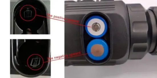 Fig. 8-1 Schematic diagram of battery installation
Product Cleaning and Maintenance
- It is prohibited to clean the device with a cleaning tool that may corrode or scratch optical glass.
- The unit can be scrubbed with a soft cloth by dipping a certain amount of alcohol.
- For optical glass devices such as eyepiece lenses and objective lenses, dust should be blown first, and then use a charcoal pen or degreasing cotton dipping non-methylated alcohol to wipe slightly.
Safety Regulation
- Please use standard batteries. Do not throw the batteries away or put them on fire after usage.
- Please use the standard charger to prevent the product from being damaged.
- Short circuit products are prohibited.
- It is prohibited to expose the product in a high-temperature environment of more than 60℃.
- It is prohibited to put the product on fire.
General Trouble Shooting
Table 9-1 General troubleshooting
| Description | Probable cause | Troubleshooting |
| Image blurring | -The focal length of the objective lens does not suit. | Adjust the focal length of the objective lens until the image becomes clear. |
| No image calibration for a long time. | Perform image calibration. | |
| Blurred vision | Sight distance inadequacy. | Adjust the sight distance of the eyepiece until the image becomes clear. |
| No analog video output | The Analog video not opening. | Open analog video output. |
| The Data cable doesn’t support data transmission. | Replace the data cable. | |
| Fail to start up | Wrong battery installation or low power. | Check the battery installation and battery power. |
| Insufficient external supply voltage. | Check the voltage of the external power supply. | |
| The attachment’s eyepiece is stuck during installation. | The eye relief mounting limit block isn’t placed parallel to the rail slot and the position is dislocation. | Lose the eyepiece, push it back to the square, and then rotate the mounting. |
| When aiming at the target, the reticle swings and cannot be aimed at the target. | The daylight sight parameter is not the correction distance of 100 yards. | Replace the daylight sight with a 100-yard sight. |
★Please contact us as soon as possible if there are some abnormalities. Private disassembly is strictly prohibited.
Appendix
User Interface Description
- Custom interface and data cable are adopted to support type-c power supply, serial port and PAL video.
- Support type-c and battery power supply, support over-voltage and under-voltage reverse connection protection.
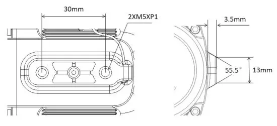
Product Dimensions
Boundary Dimension 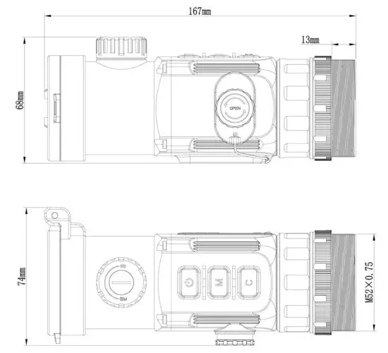
Bottom Mounting Hole Size
All rights reserved and shall not be copied and distributed in any form without written permission.


