
InfiRay Micro III 384T Xcore MicroIII Series Uncooled Thermal Imaging Module

Xcore MicroIII Series Uncooled Thermal Imaging Module User Expansion Component Manual
©IRay Technology Co.,Ltd 2021 Reserve all the right. All in this manual including texts, pictures, diagrams and other contents belong to IRay Technology Co.,Ltd (Hereinafter referred to as “Our company”or “IRay Technology”). Without the written permission, no one shall copy, photocopy, translate or disseminate all or part of this manual.
This manual is used as a guide. The photos, graphics, diagrams and illustrations provided in the manual are only used to explain, which may be different from the specific product. Please refer to the real object.We try our best to make sure the contents in this manual are accurate.We do not provide any representations or warranties in this manual.
If you need the latest version of this manual, please contact us. IRay Photoelectric recommends that you use this manual under the guidance of professionals.
Version History
| Version | Date | Description | Revised by | Checked by |
| V1.0.0 | 2019-06 | Initial version | ||
| V1.0.1 | 2020-04 | Add expansion board MRIII00V110F016C | ||
| V1.0.2 | 2020-06 | Add user expansion board of MRIII00V100F008C and MRIII00V110F017C | Ma Yanjing Lin Wenjuan | Lu Fengjuan |
| V1.0.3 | 2020-08 | Add Pin marks of the expansion component | Wu Changhao Lin Wenjuan | Lu Fengjuan |
| V1.0.4 | 2021-04 | Revise pin definition of keys | Wu Changhao Lin Wenjuan | |
| V1.0.5 | 2021-12 | Update info of expansion component MRIII00V100F012C |
The expansion components connect to the rear of module directly. Each expansion component supplies different controlling connector and video output connector, and the power protection function of over-voltage, under-voltage and reverse-connection. The default setting of digital video output is off, and can be set it on via PC software or UART command. The module supports output digital video only one channel in one time.
MRIII00V110F016C User Expansion Component
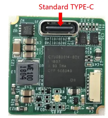 Figure 1.1 MRIII00V110F016C expansion board
MRIII00V110F016C Socket Definition
The expansion component includes USB Type C socket, which includes power supply (5V DC), one channel analog video, one channel USB2.0 connector (UVC digital video, module controller). And one USB cable is provided, one end can connect to USB Type C socket on board, and other ends is one standard USB2.0 connector and BNC connector (transmitting analog video).
Table1.1 USB2.0-Type C Socket Definition
| Pin number | Pin name | Type | Definition |
| A4,B4,A9,B9 | VBUS | Power | Power input(5VDC) |
| A1,B1 | GND | Power | Power ground(1) |
| A8,B8 | VIDEO | Output | Analog video |
| A12,B12 | VGND | Power | Analog video ground(1) |
| A6,B6 | USB_DP | Input/output | USB |
| A7,B7 | USB_DM | Input/output |
Note:(1)GND and VGND are short connected internally of module.
MRIII00V100F012C User Expansion Component
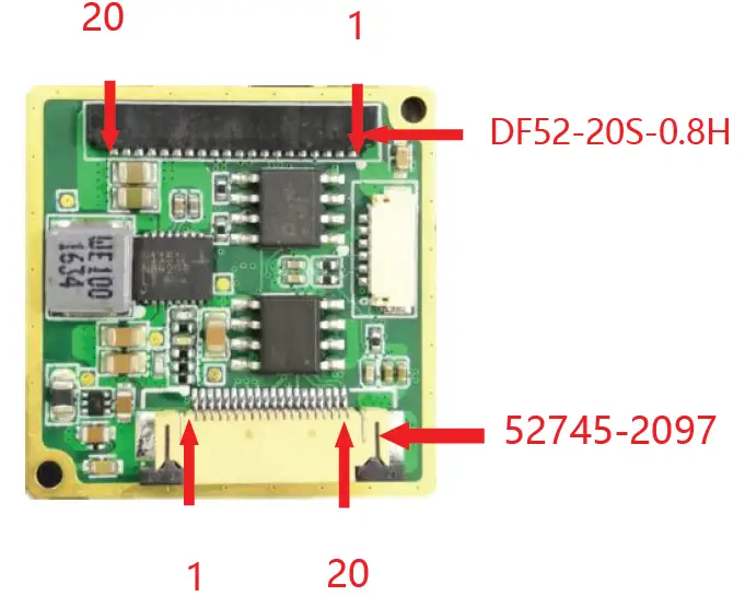 Figure 2.1 MRIII00V100F012C
MRIII00V100F012C Socket Definition
The component supplies two sockets. One is Hirose 20pin DF52-20S-0.8H socket, includes power supply (3.5~18V DC), RS232, one channel analog video in PAL format, and 4 keys board connector. Socket pins definition as table2.1. And supply one Hirose 20pins DF52-20P-0.8C cable for connecting component to other devices.
Table2.1 Hirose 20pins DF52-20S-0.8H Socket Definition
| Pin number | Pin name | Type | Definition | |
| 1、3 | VGND | Power | Analog video ground(2) | |
| 2 | VIDEO | Output | Analog video | |
| 4 | RS232_RX | Input/output | RS-232 serial communication connector(1) | |
| 5 | RS232_TX | |||
| 6、15、18、 19、20 | GND | Power | Power ground(2) | |
| 7、8、9、10 | —— | —— | N/A | |
| 11 | KEY1 |
Input | Keys connector (3.3V)(3) | M(menu) |
| 12 | KEY2 | +(plus) | ||
| 13 | KEY3 | -(minus) | ||
| 14 | KEY4 | C(Correction) | ||
| 16、17 | Power Supply | Power | Power input(3.5~18VDC)(4) | |
Note:
- TX & RX of series communication connector is for module.
- GND and VGND are short connected internally of module.
- KEY1~KEY4 are low level valid and pulled up internally on the expansion component.
- Typical power supply voltage is 12VDC.
The other interface adopts Molex 20pin connector named 52745-2097 which can be connected via FPC. It includes power supply(3.5~18VDC), UART(3.3V) communication interface, BT.656 digital video and the interface definitions are shown in table 2.2. Users can select FPC(not in standard package) to achieve the connection between thermal imaging module and other devices.
Table2.2 Molex 20pins 52745-2097 Socket Definition
| NO. | Name | Type | Description | |
| 1 | Clock |
Output |
BT.656 | Clock signal |
| 2 | DV0 | Data signal LSB | ||
| 3 | DV1 | Data signal | ||
| 4 | DV2 | Data signal | ||
| 5 | DV3 | Data signal | ||
| 6 | DV4 | Data signal | ||
| 7 | DV5 | Data signal | ||
| 8 | DV6 | Data signal | ||
| 9 | DV7 | Data signal MSB | ||
| 10、11、12、13 | GND | Power supply | Ground of power(2) | |
| 14 | —— | —— | Not available | |
| 15、16、17、18 | Power supply | Power supply | Power input(3.5~ 18VDC)(3) | |
| 19 | UART_TX(1) | Input/Output | UART communication interface(3.3V) | |
| 20 | UART_RX (1) | |||
Note:
- TX and RX of Serial Communication interfaces are relative to the imaging module;
- GND and VGND are connected internally;
- The two channels of power supply are connected internally and it is recommended to select one channel to provide power. If the two channels of power supply are provided at same time, please keep the voltages in the same. The recommended value of operation voltage is 12VDC.
BT.656 Digital Video
The digital video of BT.656 consists of one clock signal (Clock) and eight data signals (DV0~DV7). The BT.656 digital video supports the functions of brightness/contrast adjustment, polarity selection, palette selection, reticle control, digital zoom and image mirror. And the output data of BT.656 must be the DRC. The BT.656 format follows the analog video format. If the analog video is in PAL/NTSC format, the BT656 is same as in PAL/NTSC format respectively.
MRIII00V100F011C User Expansion Component
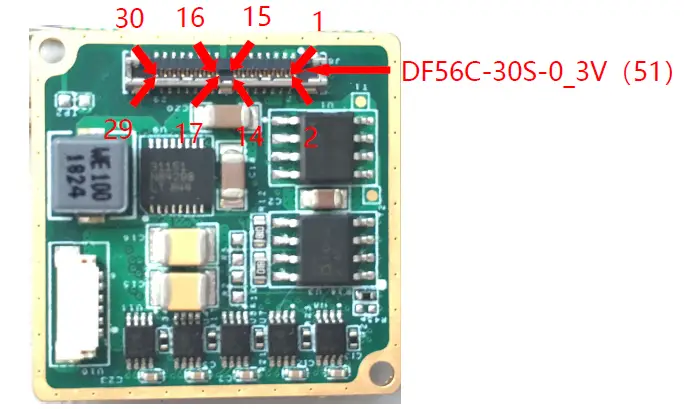 Figure 3.1 MRIII00V100F011C expansion component
MRIII00V100F011C Socket Definition
The component supports a socket of Hirose 30pins DF56C-30S-0_3V( 51 ) , includes power supply (3.5~18VDC), RS232&RS422, one channel analog video output, LVDS_H digital video output, and 4keys board connector. And supply a Hirose 30pins connector to connect DF56C-30S-0_3V ( 51 ) socket, the length of cable is 9~11cm, the other end of cable can connect to other devices.
Table3.1 Hirose 30Pins DF56C-30S-0_3V(51) Socket Definition
| NO. | Name | Type | Description | |
| 4、5、6、19、 20 | GND | Power | Power ground(3) | |
| 1、2、3 | Power Supply | Power | Power input(3.5~18VDC) (1) | |
| 11 | RS-422_RX+ |
Input/Output | RS-422 communication interface(2) | |
| 12 | RS-422_RX- | |||
| 13 | RS-422_TX+ | |||
| 14 | RS-422_TX- | |||
| 9 | RS-232_RX | Input/Output | RS-232 communication interface(2) | |
| 10 | RS-232_TX | |||
| 29 | LVDS_CLK+ | Output |
LVDS_H digital video (2.5V) | Clock signal |
| 30 | LVDS_CLK- | |||
| 27 | LVDS_DATA0+ | Output | Data signal | |
| 28 | LVDS_DATA0- | |||
| 25 | LVDS_DATA1+ | Output | Data signal | |
| 26 | LVDS_DATA1- | |||
| 23 | LVDS_DATA2+ | Output | Data signal | |
| 24 | LVDS_DATA2- | |||
| 21 | LVDS_DATA3+ | Output | Data signal | |
| 22 | LVDS_DATA3- | |||
| 8 | VGND | Power | Analog video ground(3) | |
| 7 | VIDEO | Output | Analog video | |
| 15 | KEY1 | Input | Keys connector (3.3V)(4) | M(menu) |
| 16 | KEY2 | Input | +(plus) | |
| 17 | KEY3 | Input | -(minus) | |
| 18 | KEY4 | Input | C(Correction) | |
Note:
- The recommended value of operation voltage is 12VDC.
- TX and RX of Serial Communication interfaces are relative to the imaging module.
- GND and VGND are connected internally.
- KEY1~KEY4 are low level valid and pulled up internally inside the expansion component.
LVDS_H Digital Video
LVDS_H digital video includes one clock signal(LVDS_CLK), and four data signals(LVDS_DATA1, LVDS_DATA2, LVDS_DATA3 and LVDS_DATA4). It is convenient to be parsed by mainstream encode/code chip.
LVDS_H digital video can be turned on/off by control command. When it is turned on, ORG data, NUC data, DNS data, DRC data and Temp data can be selected.
When DRC data is selected, function of digital zoom and menu display are not supportable.
Table 3.2 LVDS_H Clock frequency
| Module | Clock frequency (LVDS_CLK) |
| M3640 | 33.75MHz |
| M3384 | 22.50MHz |
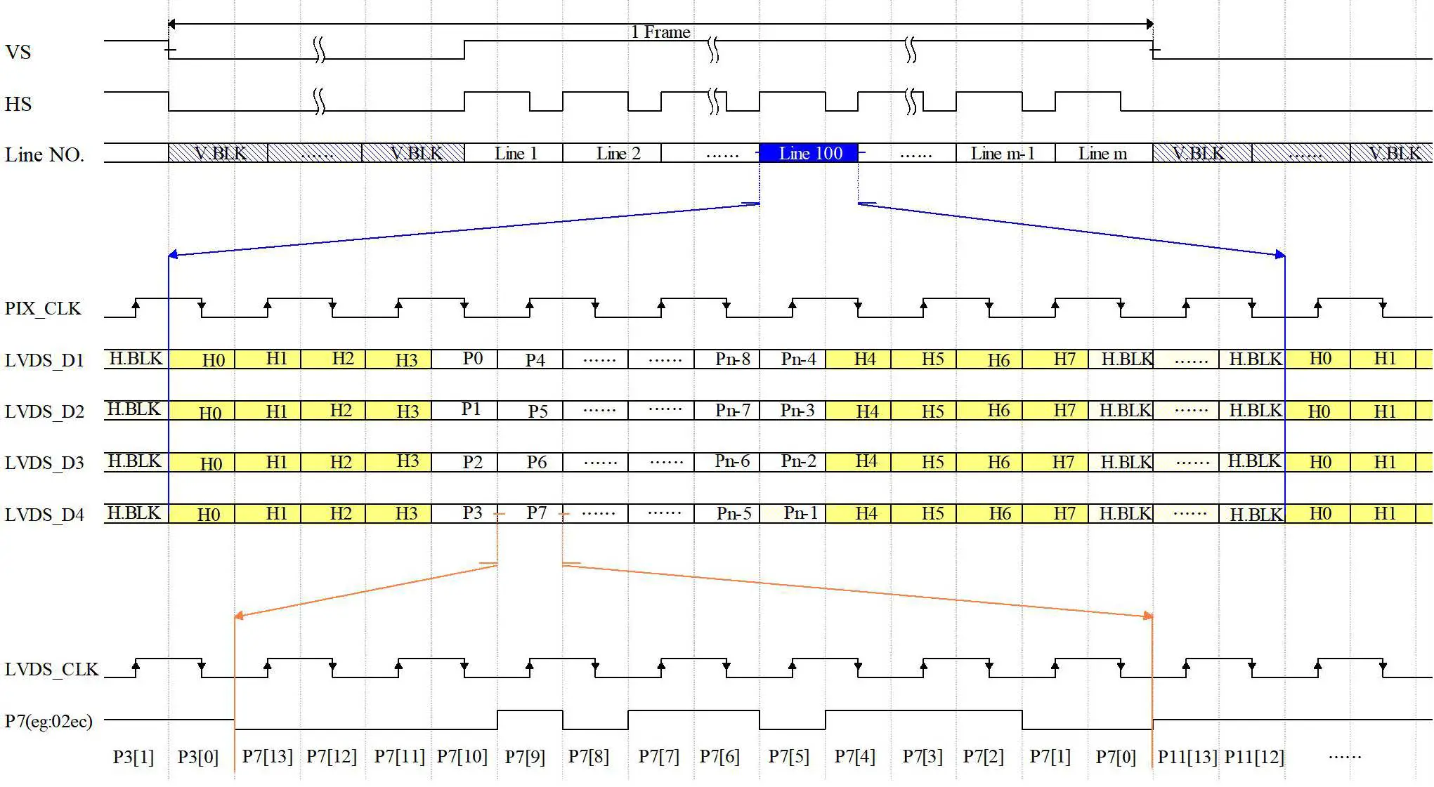 Figure 3.2 LVDS_H Digital Video Timing Diagram n×m Array
MRIII00V100F008C User Expansion Component
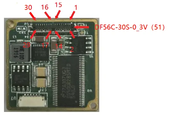 Figure4.1 MRIII00V100F008C Expansion Board
MRIII00V100F008C Socket Definition
The component supports a socket of Hirose 30pins DF56C-30S-0_3V( 51 ) , includes power supply (3.5~18VDC), RS232&RS422, one channel analog video output, Camera LINK digital video output, and 4keys connector. And supply a Hirose 30pins connector to connect DF56C-30S-0_3V(51)socket, the length of cable is 9~11cm, the other end of cable can connect to other devices.
Table 4.1 Hirose 30pin DF56C-30S-0_3V(51)Socket Definition
| Pin No. | Pin Name | Type | Definition |
| 4、5、6、19、 20 | GND | Power | Power ground(3) |
| Pin No. | Pin Name | Type | Definition | |
| 1、2、3 | Power Supply | Power | Power input(3.5~18VDC)(1) | |
| 11 | RS-422_RX+ |
Input/output | RS-422 serial communication interface(2) | |
| 12 | RS-422_RX- | |||
| 13 | RS-422_TX+ | |||
| 14 | RS-422_TX- | |||
| 9 | RS-232_RX | Input/output | RS-232 serial communication interface(2) | |
| 10 | RS-232_TX | |||
| 29 | CMLK_CLK+ | Output |
Camera LINK digital video | Clock signal |
| 30 | CMLK _CLK- | |||
| 27 | CMLK _DATA0+ | Output | Data signal | |
| 28 | CMLK _DATA0- | |||
| 25 | CMLK _DATA1+ | Output | Data signal | |
| 26 | CMLK _DATA1- | |||
| 23 | CMLK _DATA2+ | Output | Data signal | |
| 24 | CMLK _DATA2- | |||
| 21 | CMLK _DATA3+ | Output | Data signal | |
| 22 | CMLK _DATA3- | |||
| 8 | VGND | Power | Analog video ground(3) | |
| 7 | VIDEO | Output | Analog video | |
| 15 | KEY1 | Input | Key interface (3.3V)(4) | M(menu) |
| 16 | KEY2 | Input | +(plus) | |
| 17 | KEY3 | Input | -(minus) | |
| 18 | KEY4 | Input | C(Correction) | |
Note:
- The recommended value of operation voltage is 12VDC.
- TX and RX of Serial Communication interfaces are relative to the imaging module.
- GND and VGND are connected internally.
- KEY1~KEY4 are low level valid and pulled up internally inside the expansion component.
MRIII00V110F017C User Expansion Component
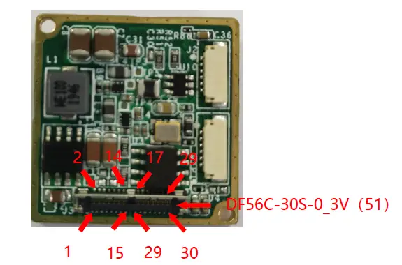 Figure 5.1 MRIII00V110F017C Expansion Board
MRIII00V110F017C Socket Definition
The component supports a socket of Hirose 30pins DF56C-30S-0_3V( 51 ) , includes power supply (3.5~18VDC), RS232&RS422, one channel analog video output, MIPI digital video output, and 4keys connector. And supply a Hirose 30pins connector to connect DF56C-30S-0_3V(51)socket, the length of cable is 9~11cm, the other end of cable can connect to other devices.
Table 5.1 Hirose 30pin DF56C-30S-0_3V(51)Socket Definition
| Pin No. | Pin Name | Type | Definition | |
| 4、5、6、19、 20 | GND | Power | Power ground(3) | |
| 1、2、3 | Power Supply | Power | Power input(3.5~18VDC) (1) | |
| 11 | RS-422_RX+ |
Input/output | RS-422 serial communication interface(2) | |
| 12 | RS-422_RX- | |||
| 13 | RS-422_TX+ | |||
| 14 | RS-422_TX- | |||
| 9 | RS-232_RX | Input/output | RS-232 serial communication interface(2) | |
| 10 | RS-232_TX | |||
| 29 | MIPI_CLK+ | Output |
MIPI digital video | Clock Signal |
| 30 | MIPI_CLK- | |||
| 27 | MIPI_DATA0+ | Output | Data Signal | |
| 28 | MIPI_DATA0- | |||
| 25 | MIPI_DATA1+ | Output | Data Signal | |
| 26 | MIPI_DATA1- | |||
| 23 | MIPI_DATA2+ | Output | Data Signal | |
| Pin No. | Pin Name | Type | Definition | |
| 24 | MIPI_DATA2- | |||
| 21 | MIPI_DATA3+ | Output | Data Signal | |
| 22 | MIPI_DATA3- | |||
| 8 | VGND | Power | Analog video ground(3) | |
| 7 | VIDEO | Output | Analog video | |
| 15 | KEY1 | Input | Key interface (3.3V) (4) | M(menu) |
| 16 | KEY2 | Input | +(plus) | |
| 17 | KEY3 | Input | -(minus) | |
| 18 | KEY4 | Input | C(Correction) | |
Note:
- The recommended value of operation voltage is 12VDC.
- TX and RX of Serial Communication interfaces are relative to the imaging module.
- GND and VGND are connected internally.
- KEY1~KEY4 are low level valid and pulled up internally inside the expansion component.
Announcements
To protect you and others from injury or to protect your equipment from damage, please read all of the following information before using your equipment.
- The product should not be made towards the sun directly and other high-intensity radiation sources;
- The optimal environment temperature for operating is – 20℃ to 50℃;
- Do not touch or hit the detector window with hands or other objects;
- Do not touch the equipment and cables with wet hands;
- Please do not bend or damage cables;
- Do not scrub your equipment with diluents;
- Should not unplug and plug other cables without disconnecting the power supply;
- Wrong cable should not be connected in case that brings damages to the equipment;
- Please pay attention to prevent static electricity;
- Please do not disassemble the equipment. If there is any fault, please contact our company, and professional personnel will carry out maintenance.
Supports and Services
Technical Supports
- Refitting and designing schemes according to users’ application requirements.
- Providing professional and systematic technical training for users and operators.
After-sales Services
Xcore MicroIII series uncooled thermal imaging core is developed by our company. It has good after-sales service guarantee such as equipment maintenance. If you have any requirements, please contact us.
Company Information
IRay Technology Co., Ltd.
Website:www.infiray.com
Tel:86-0535-3410623
Fax:86-0535-3410610
E-mail:[email protected]
Address:No. 11 Guiyang Street, YEDA Yantai 264006, P. R. China


