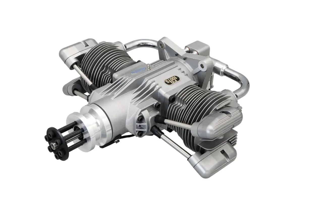
SAITO FG-100TS Boxer Benzin Motor 2 Zylinder 4T Motor Instruction Manual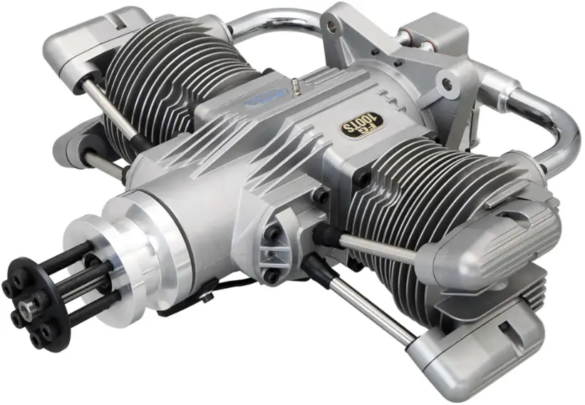
Specification
| Bore | Φ43.6mm x 2 | Stroke | 33.6mm x 2 | Disp. | 100.3cc | Applications | Acro-2st 70cc class Scale-2st 70cc-100cc class | |||||
| Weight (Approx.) | Main body : 4,040 g / Mufflers : 180g / Ignition : 160g | RPM range | Approx.1,000-6,000rpm | Max on ground | Approx. 5,500-6,000rpm | |||||||
| Propeller | 25” x 12“ ~27” x 10” | Plug | CM-6 | Battery for ignition system | Voltage:6-12V, greater than 1,000mA ※ | |||||||
| Standard |
| 1pc 2pcs |
| 1pc 1set |
| 1pc 1pc | ||||||
| accessories |
| 1set 1set |
| 1set 1pc |
| 1pc | ||||||
| Optional parts |
| |||||||||||
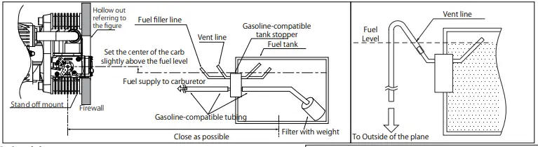
Fuel
- The fuel is a mixture of regular gasoline or high-octane gasoline and high-quality 2-stroke engine oil.
- Example of oil recommendation]
- Klotz KL-200 Original Technip late
- Deluxe Materials Power Model 2T-S
- ENEOS RACING SPEC PRO-2T (SAITO STANDARD) etc.
If such oils are not available in your country, then please ask the official SAITO distributor in your country for an alternative.
- Be sure to use the mixture “gasoline : oil =15~20 : 1” by volume ratio. (Ex. 1000ml of gasoline should be mixed with more than 50ml of oil ).
- During the break-in process, use 15:1 mixed fuel to ensure the best lubrication for initial running.
- Any damage caused by the fuel used, in which the oil ratio is lower than 20:1 will not be covered by warranty.
- Do not use gasoline containing ethanol. It may cause not only power loss but also corrosion inside the engine.

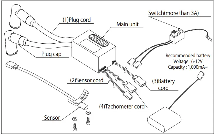
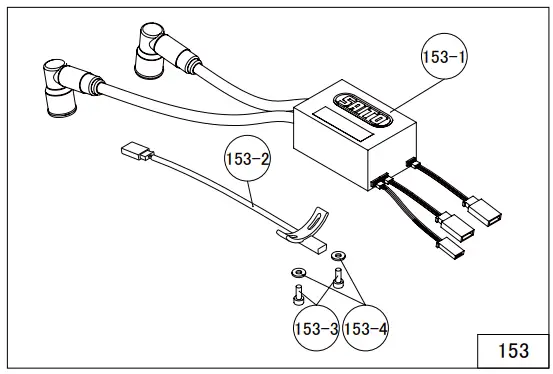
Ignition
- Ignition arrangement- Place the main unit as far from other electrical devices as possible.
- Plug cord(meshed high tension cord)
2 cords compatible for left/right cylinder. Insert the cap deelpy onto the plug to make sure it will not come off. - Sensor cord
Connect with the cord from the sensor attached to the engine. - Battery cord (black / red cord)
Use a fully charged battery that has adequate spec. (6-12V, more than 1000mA is recommended.). Between the battery and main unit, make sure to install a heavy duty switch whose capacity is higher than 3A. - Tachometer cord (optional)
Connect the digital tachometer (Option). Otherwise the connector is normally vacant.
- Plug cord(meshed high tension cord)
Propeller
- Recommended propeller is Mejzlik 26 x 12 which brings approx. 5,500rpm (or Falcon D26”xP12” brings approx. 5,000rpm).
- Use a well-balanced one. Never use the propeller that has been scratched or damaged even if slightly.
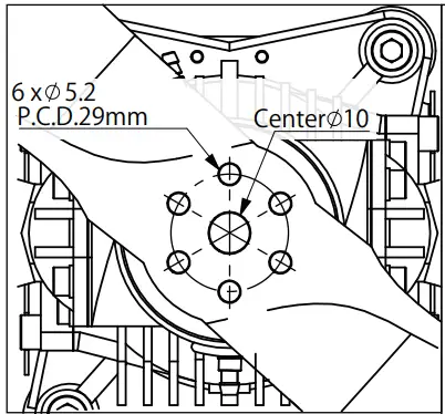
- Open a hole exactly in propeller hub (boss) in advance as shown in the right figure using drilling tool and propeller washer.
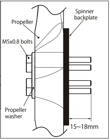
- Pass the propeller through the shaft and tighten the six bolts inserting the propeller washer in the order of diagonal. ※The appropriate length of the bolts may be different depending on the thickness of the propeller hub (boss). Depending on the propeller and spinner backplate you use, use M5 x 0.8 bolts with length that protrude 15~ 18mm. (Screw length of standard accessory is 55mm)
- As the propeller is compressed slightly, tighten the 6 bolts every hour of operation.


Method of choke
(No need when you use starter)
- Choking is the means by which fuel is fed to the engine when you start it by hand flipping. Thus it is unnecessary when using starter. Starting with a electric starter is recommended for safety.
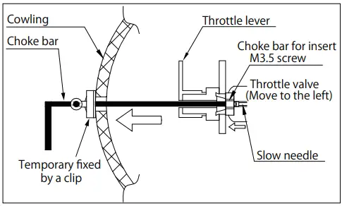
- In advance, make a thin hole in the cowling to insert the choke bar / slow needle adjustment bar.
- During choking, be sure to turn off the ignition switch.
- As shown in the fig, pass the choke bar (with M3.5 thread on its tip) through the hole in the cowling. Then turn the bar to insert into the M3.5 internal thread at the center of the throttle lever.
- Fully close the throttle and pull the choke bar and fix it with a clip or clamp as shown in the fig so that it may not go back to the previous position.
- Grasp the prop by hand and turn it several times in the direction of normal operation (CCW) until the carburetor generates hissing-like sound. After hearing this sound for about 5 times, quickly flip the prop approximately 10 times.
- Remove the choke bar. Then power on the ignition system and flip the prop quickly to start the engine. If the engine doesn’t start, repeat the choking procedure.

Break-in MOST IMPORTANT
- Before starting the engine, inject a suitable amount ( approx. 20~30cc ) of engine oil into the lubrication nipple on the crankcase using a syringe or pump while turning the propeller by hand. After that, plug this nipple. As excess is discharged from the breather nipple, attach a tube to the breather nipple.
- Prop-recommendation : Mejzlik-26×12.
- Use 15:1 fuel:oil ratio for break-in.
- Never make the fuel mixture lean during Break-in.
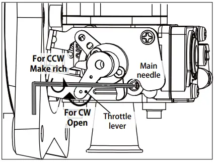
It could cause seizure even during idling or low speed running. - Before starting the engine, open the main needle Approx. 3 turns open (CCW) from fully closed.
- Start the engine (using a starter is recommended for safety).
- Soon after starting, Open the throttle gradually up to over half open. In the meantime turn the main needle CCW. Continue to turn the main needle CCW until the RPM declines, keeping the
throttle opened over half. - If opening main needle doesn’t drop RPM, then open the slow needle too.
- Run in this very rich condition for 1 liter of fuel.
- Now “initial” break-in is done,

Adjustment of carburetor after initial break-in
Needle reference position (Set after initial break-in)
- Start the engine after adjusting the needle to the following reference value.
- Main needle: Approx.2.5~3 turns CCW from fully closed
- Slow needle: Approx. 4 turns CCW from fully closed (Then throttle should be fully closed)
- Actually, the best position of the needles vary depending on the prop, temperature, humidity and so on. Please adjust as necessary after observing the engine performance during flight.
Peak adjustment
- After starting the engine, warm up for approx. 30 seconds at low speed.
- Achieve the peak at full throttle.
→Turn the main needle CW gradually to the position where the RPM is greatest (the peak). Continuing to turn the needle CW past the peak could lead to seizure so turn it slowly and carefully. If the RPM suddenly decreases after passing the peak, instantly turn the main needle CCW to again increase the RPM. Otherwise it could damage the engine seriously. - Once achieving peak RPM, return the throttle to low speed. Make a note of the position of main needle at the peak at that time. ( How many turns you did CW based on the reference value. )
Slow needle Adjustment
- After achieving peak RPM, next is slow needle adjustment. Open the throttle from low RPM to full throttle quickly.
- If the engine hesitates for a moment or stalls before the engine reaches max RPM, Itʼs because the mixture is too lean. Then turn the slow needle CCW slightly.
- If the engine is slow to reach peak RPM (full throttle set), itʼs because the mixture is too rich. Then turn the slow needle CW slightly.
- Adjust the slow needle as above until the RPM follows the throttle movement smoothly. The important point is to adjust the slow needle AFTER the main needle has been adjusted to its peak.
- Now break-in at ground level is done. Adjust tappets by the method described later.
Pre-flight / Flight adjustment
- When the slow needle adjustment is done, check the response by revving up from low speed to full throttle quickly several times.
- Open the throttle fully and turn the main needle CCW approx. 60~90 degrees from the peak position. This is to make the fuel mixture richer in the air where the RPM get higher than on the ground.
- After all adjustments are made, fly your aircraft and fine tune the engine according to the situation. Basically tuning should be done with the main needle.
Readjustment of the slow needle is rarely needed if the first adjustment of the slow needle has been done successfully
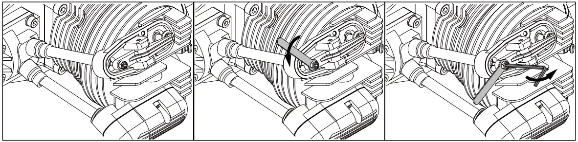
Tappet adjustment
The valve clearance should be checked and adjusted after break-in and every time after two hours while the engine is cold. Before adjusting tappet gaps, tighten up the screws around cylinders etc.
- Remove the spark plug and rocker arm covers of a cylinder.
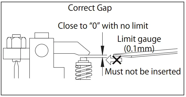
Then turn the prop CCW by hand to place the piston at TDC of compression stroke. - Loosen the lock nut and adjust the gap by hexagonal wrench until you get the correct gap for both of intake & exhaust.
- Once the gap is set, tighten the lock nut and attach the plug and covers. Then do the same adjustment for the other cylinder.

- Turn the prop by hand to check if the compression is enough. If the gap is less than 0, the valve is always opened slightly and will lose compression. Then adjust again.

Note:
- As it uses oil-mixed fuel, the plane may sometimes get dirty from the exhaust.
- Use a reliable and well-balanced prop. Otherwise it may cause an abnormal vibration and could result in a serious accident.
- During operation, all engine screws can loosen due to metal heat expansion. Check and tighten occasionally.
- When the exhaust valve gets dull by carbon or sludge especially in cold atmosphere, remove the rocker cover and apply some anti-rust spray to the exhaust valve to help the valve to move smoothly.
- Pay attention to the surroundings so as not to disturb others by noise and exhaust.
- Always keep spectators behind the engine when operating the engine.
- As exhaust smoke is harmful, be careful not to breathe in or otherwise expose yourself to its harmful effects.
- Pay attention not to touch the rotating propeller when starting engine, and move to rear side of the aircraft once the engine is started.
- All responsibilities for the use of the engine, and other obligations and responsibilities based on laws, regulations, etc. are borne by the purchaser and the user, and SAITO SEISAKUSHO CO., LTD. is exempt from any responsibilities.
Warranty: - If there is any deficiency from the factory concerning manufacture, please consult with the shop or distributor you bought from. Our company will be responsible for repair. However, any failure or trouble caused by unnecessary disassembly, modification, or other uses than those provided in the instruction manual is not subject to warranty.
- Ignition system is subject to the warranty only for initial failure. Once the system has been activated successfully, it will no longer be subject to warranty.
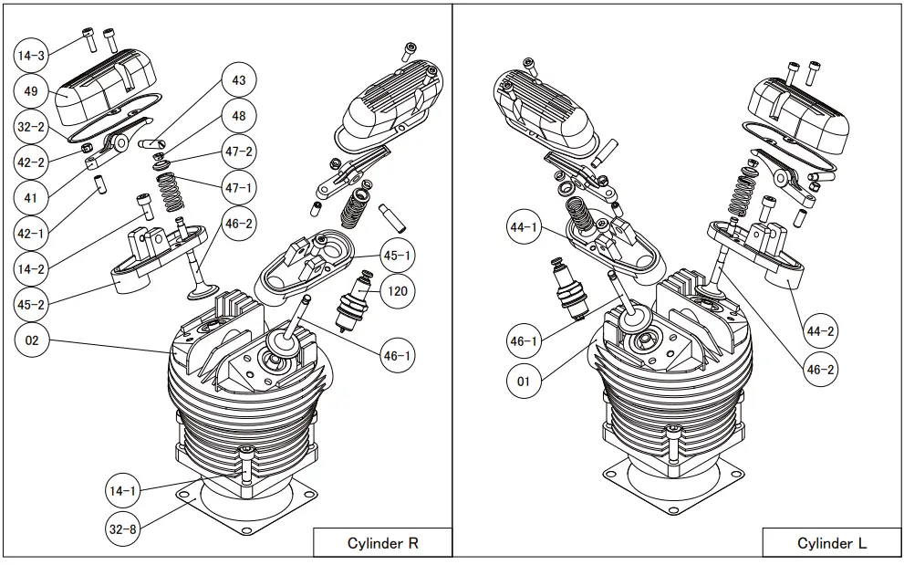
Parts Description
| No. | PART NAME | QʼTY |
| 01 | Cylinder(Left) | 1 |
| 02 | Cylinder(Right) | 1 |
| 06 | Piston | 2 |
| 07 | Piston Pin | 2 |
| 08 | Piston Pin Retainer | 4 |
| 09 | Piston Ring | 2 |
| 10 | Connecting Rod ( Conrod) | 2 |
| 13 | Conrod Screw | 4 |
| 14 | Cylinder Screw Set | 1 set |
| 14-1,-2,-3,-4 | ||
| 15 | Crankcase | 1 |
| 19 | Breather Nipple | 1 |
| 20 | Front Bearing | 1 |
| 21 | Main Bearing | 1 |
| 22 | Rear Bearing | 1 |
| 23 | Crankshaft | 1 |
| 27 | Taper Collet & Drive Flange | 1 set |
| 27-1,-2 | ||
| 27-3 | Drive Flange Nut | 1 |
| 27-4 | Drive Flange Washer | 1 |
| 27-5 | Parallel Key | 1 |
| 28 | Prop Washer & Screw Set | 1 set |
| 28-1,-2 | ||
| 31 | Crankcase Screw Set | 1 set |
| 31-1,-2,-3 | ||
| 32 | Engine Gasket Set | 1 set |
| 32-1,-2,-3,-4,-8 | ||
| 33-1 | Cam Gear Housing for Cylinder (Left) | 1 |
| 33-2 | Cam Gear Housing for Cylinder (Right) | 1 |
| 34 | Cam Gear for Cylinder (Left) | 1 |
| 35 | Cam Gear for Cylinder (Right) | 1 |
| 36 | Cam Gear Shaft | 1 |
| 37 | Steel Washer | 1 |
| 38 | Tappet(Valve Lifter) | 4 |
| 39 | Pushrod | 4 |
| 40 | Pushrod Cover & Rubber Seal | 1 set |
| 40-1,-2,-3 | ||
| 41 | Rocker Arm | 4 |
| No. | PART NAME | QʼTY |
| 42 | Rocker Arm Screw & Nut | 1 set |
| 42-1,-2 | ||
| 43 | Rocker Arm Pin | 4 |
| 44-1 | Intake Rocker Arm Bracket for Cylinder (Left) | 1 |
| 44-2 | Exhaust Rocker Arm Bracket for Cylinder (Left) | 1 |
| 45-1 | Intake Rocker Arm Bracket for Cylinder (Right) | 1 |
| 45-2 | Exhaust Rocker Arm Bracket for Cylinder (Right) | 1 |
| 46-1 | Intake Valve | 2 |
| 46-2 | Exhaust Valve | 2 |
| 47 | Valve Spring, Retainer, Cotter | 1 set |
| 47-1,-2,48 | ||
| 48 | Cotter(Valve Spring retainer) | 4 |
| 49 | Rocker Arm Cover | 4 |
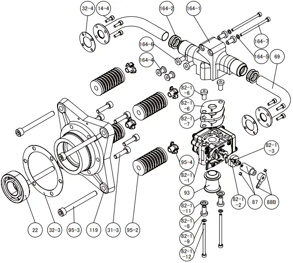
| 69 | Intake Pipe | 2 |
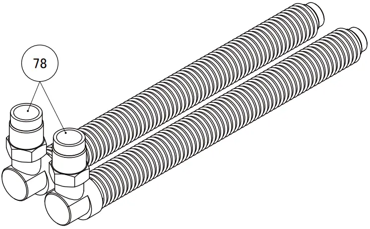
| 78 | Flexible Muffler | 2 |
| 82-1 | Carburetor Complete | 1set |
| 82-1-1,-1-2,-1-3,-1-6,-1-7,-1-8, -1-9,-1-11,-1-12,87,88,93 | ||
| 83-1 | Carburetor Body Assembly | 1 set |
| 82-1-1,-1-2,-1-3,88 | ||
| 88B | Throttle Lever | 1 |
| 90 | Carburetor Screw Set | 1 set |
| 82-1-9,-1-11,-1-12 | ||
| 91 | Carburetor Gasket Set | 1 set |
| 82-1-6,-1-7,-1-8 | ||
| 93 | Air Funnel | 1 |
| 95 | Engine Mount Set | 1 set |
| 95-2,-3,-4 | ||
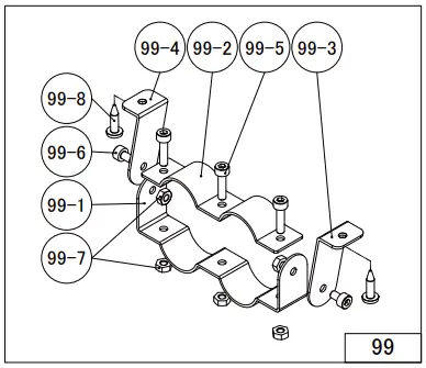
| 99 | Muffler Bracket Set | 1 set |
| 99-1,-2,-3,-4,-5,-6,-7,-8 | ||
| 119 | Rear Cover Mount | 1 |
| 120 | Spark Plug(NGK CM-6) | 2 |
| 153 | Electronic Ignition System | 1 set |
| 153-1,-2,-3,-4 | ||
| 164 | Intake Manifold | 1 set |
| 164-1,-2,-4,-5,-6,-7 | ||
| 175 | Initial Lube Nipple | 1 |
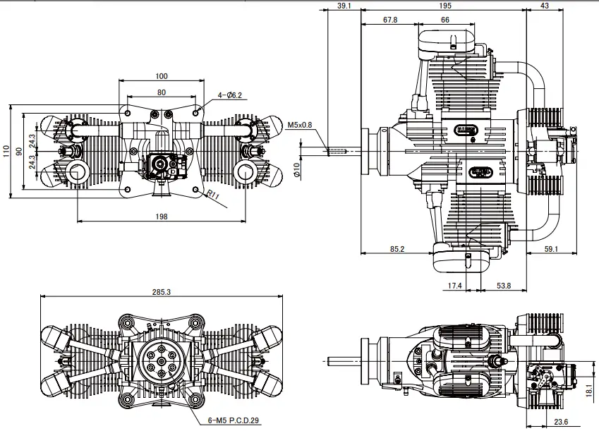
Product Diagram
Out Side Diagram
Customer Support
AITO SEISAKUSHO, CO., LTD.
www.saito-mfg.com
22-7, 3-chome, Tokagi, Ichikawa-shi, Chiba prefecture 272-0024, Japan
Phone: 047-378-4156 FAX: 047-378-4155


