![]()
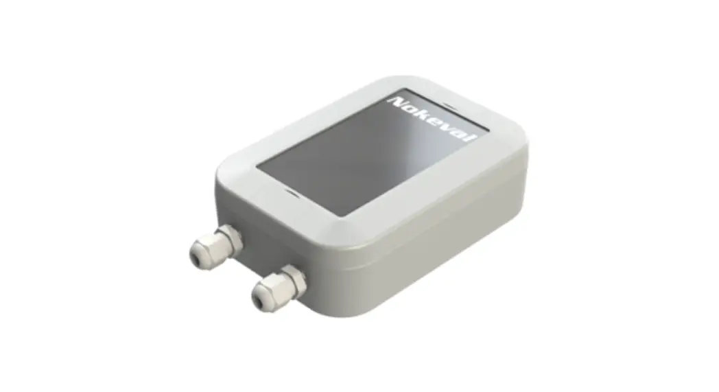
Stable-LWEU-T-DI
Manual
ID11554 V14 20.7.2021
Firmware 1.0-1.0
User Guide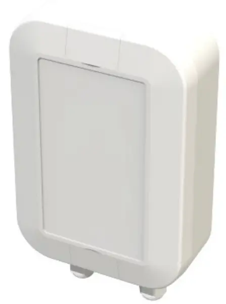
Introduction
The Stable-LWEU-T-DI is a temperature transmitter. The device measures temperature using two thermocouples. Stable-LWEU-T-DI uses LoRaWAN for communication with the cloud.
Before using the 868 MHz radio, make sure it is legal in your country.
Installation
Mounting
Mount the device to wall or another suitable vertical surface. Mounting position, cable outlets downward.
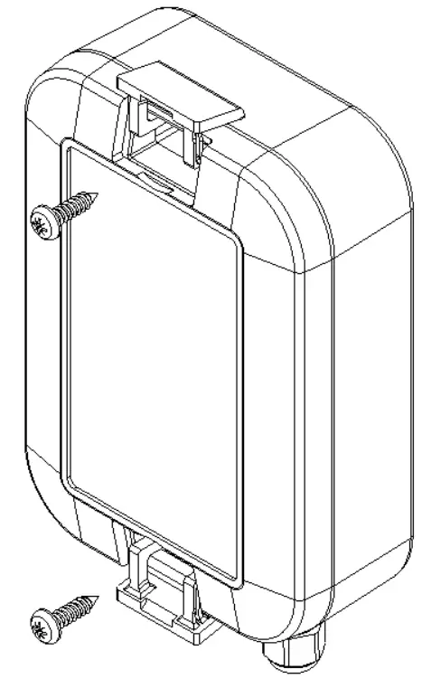
- Open the lids with flat screwdriver.
- Mount device with pan head screw, ø4.2mm max., length 10mm min.
- Close the lids.
Power supplies
The Stable-LWEU-T-DI is powered with a 3.6V Lithium Thionyl battery pack.
The device is supplied with batteries already installed, so it is ready to be used.
Settings
The Stable-LWEU-T-DI works with its default settings and no parameter configuration is normally required. However, if it is necessary to change the settings of the device, it can be done with Nokeval’s MekuWin software (available for free at www.nokeval.com). Following procedure should be followed in order to get access to the settings:
- Open the enclosure by removing the 6 screws.
- Connect a micro-USB cable to the connector, and the other end of the cable to a computer.
- If Windows requests for a driver, download it at www.nokeval.com > Support, unzip it to a temporary folder, and show that directory as the location for the driver. If there are problems during the installation, try pushing the button every 5-15 seconds or keeping it pressed so that the Stable-LWEU-T-DI will not shut down its USB port.
- Launch the MekuWin program.
- In MekuWin, choose the right COM-port form the Ports-menu. If the port is not visible, try pushing the button on the Stable-LWEU-T-DI to wake up the port.
- From the Port settings -menu, choose Protocol = ModbusRTU, Address = 1.
- Click Direct.
- A new window will open for the settings.
The configuration menu includes the following settings:
- Protection
o Describes password protection status “None”, “Locked”, “Unlocked”. - Password input/setup
o Unlock protection or change password. See “Protecting the settings” section below for details. - Transmission Period
o Time between transmissions with options from ranging 5 minutes to 6 hours. Default is 30 min. - Trigger high temperature
o Temperature measurement value which triggers an alarm state with more frequent transmissions (same interval as Measurement Period). - Measurement Period
o Time between measurements with options ranging from 1 minute to 1 hour. Default is 2 minutes. The measurements are transmitted only if above Trigger high temperature, or if a digital input has changed. - Digital inputs enabled
o If enabled, all 3 digital inputs are measured, and a transmission is done when one of their states changes. If disabled, none of the digital inputs are measured. - Pt100 wire select status
o Display status, jumper is used this reads e.g. “Jumper selected 3-wire”. If jumper is not used to select the wiring type, it reads “Menu selected wires”. - Pt100 wire select
o Pt100 wiring selection: 2-wire, 3-wire, or 4-wire. Only applicable if the above status is “Menu selected wires” - LoRaWAN
o If the Stable-LWEU-T-DI is used with the Nokeval cloud platform, the default settings are ok. If you wish to manually set the LoRaWAN credentials and/or integrate it with your cloud platform, see “LoRaWAN settings” and “Uplink payload structure” chapters.
Protecting the settings
To protect the settings from being easily adjusted, the configuration menu provides a password box. The password can be formed using up to 16 characters. From the next MekuWin session, the settings can’t be adjusted without knowing the password.
If the displayed status is “Locked”, changes will not be saved to the device. Write the correct password in the “Password input” field and press enter to unlock.
If displayed status is “Unlocked”, the settings and password can be changed and the menu will become locked again after menu is closed.
Note that the password cannot be reset by the user. If the password is forgotten, the password reset can only be made by the manufacturer. Please make sure that the password is remembered if changed.
Operation
After the Stable-LWEU-T-DI is successfully installed, it operates on its own. However, there are some considerations that are good to know when using the Stable-LWEU-T-DI.
Temperature measurement
Temperatures are given in °C. The device supports, 2-wire, 3-wire and 4-wire Pt100 measurements, selection is described in the Settings section.
Transmissions become more frequent when temperature result is above the “Trigger high temperature” value as described in the Settings section.
Digital inputs
The device has 3 digital input ports, on the spring connector next to the “Digital inputs” text on the PCB.
The first 3 from the left are the inputs, and the rightmost port on the connector is ground.
The inputs are read every measurement period (default 2 minutes), and a transmission is triggered if any of the input values have changed after the previous reading.
Monitor menu
In MekuWin Mon-menu, you can monitor the measurement readings. The sensors are kept continuously on while MekuWin is open. The values update at the rate the sensor can produce new readings.
Information about LoRaWAN is also displayed to help with potential connection issues.
Cal menu
The calibration menu settings are only for the manufacturer use. They are not explained in this manual.
LoRaWAN settings
Conf menu
Quality
- Unidirectional – uplinks are sent as unconfirmed data with 1 attempt. Acknowledgement is not requested.
- Bidirectional – uplinks are sent as confirmed data. Acknowledgement is requested, and up to 3 attempts are used if acknowledgement is not received.
DevEUI (readonly) – shows the DevEUI of the device. Note that DevEUI can’t be modified.
LoRaWAN credentials
These should be only changed if manually provisioning the device to your own system.
AppKey, AppSKey, NwkSKey: If set, these are displayed as “***” when the menu is re-opened. They can’t be read from the device afterwards.
The keys and EUI:s are written as hex symbols 0-9/A-F, 4 bits per symbol.
- OTAA – Activation mode. If toggled on, Over-the-air-activation is used, else Activation by personalization is used.
- (OTAA mode only) AppEUI – 16 hex symbols
- (OTAA mode only) AppKey – 32 hex symbols
- (ABP mode only) DevAddr – 8 hex symbols
- (ABP mode only) AppSKey – 32 hex symbols
- (ABP mode only) NwkSKey – 32 hex symbols
Other LoRaWAN details
The device always uses Adaptive Data Rate. If it receives no messages from server for 2 subsequent messages, it will lower data rate by 1 step. Then it will lower the data rate by 1 step after every 2 messages until a message is received or data rate 0 is reached. When the device is connected to server, the MAC layer controls the data rate.
Uplink payload structure
This information is only relevant for integrating the Stable-LWEU-T-DI with customer’s own cloud platform.
The payload data format consists of a protocol version field and 1 or more messages in length-type-data format. Example payloads are presented at the end of this section for reference.
| Size | Name | Meaning |
| 1B | Protocol version | Version=1 |
| XB | 1 or more messages | Messages in format presented below. |
| 1B | Message length | Bits 0:6 – Message length in bytes, excluding length field and optional age field. Bit 7: If 1, age field is included. |
| (2B) | Optional age field | Age, uint16 * 60 seconds |
| 1B | Message type | Type, e.g. 11 = Flagged utility |
| XB | Message data | Data based on message type |
Message types
Message types:
- 10 Formatted measurement data
- 11 Flagged utility
- 12 Debug
The device may send other message types but those should be ignored. Start of next record can be found based on the length field at start of every message.
Type 10: Measurement data
Measurement data using bit-flags to describe which measurement fields are included. If the device failed to measure a value, that field will be missing. The format additionally contains status information bitflags field and related to measurements after the measurement data section.
After measurement data, has status bitflags field describing which status fields are included, similarly to the measurement bitflags. Generally if the device failed to produce a measurement, it will have a status code to help identify the issue.
| Size | Name | Value/Meaning |
| 2B | Measurement format | Always 4. |
| 1B | Measurement flags | Tells which of the measurement fields are included. E.g. 0000 1111 = All 4 fields 0000 0101 = Temperature 1, internal temperature |
| 3B | 0 – Temperature Pt100 | Conversion: int24/100 ( o C) |
| 3B | 1 – Reserved | — |
| 2B | 2 – Internal temperature | int16/100 ( o C) |
| 1B | 3 – Digital inputs x4 | One bit per digital input bit 0 – DI1 (least significant bit) bit 1 – DI2 bit 2 – DI3 bit 3 – DI4 |
| 1B | 3 – Reserved | — |
| 1B | Status flags | Tells which of the measurement status fields are included. Same logic as Measurement flags field |
| 1B | 0 – Temperature 1 status | 0: Reserved for future use 1+: error number |
| 1B | 1 – Reserved | -||- |
| 1B | 2 – Internal temperature status | -||- |
| 1B | 3 – Digital inputs status | -||- (Shared status value for all digital inputs) |
Type 11: Utility
Contains utility information about the device. Uses bit flags to describe which fields are included in the message, similar to message type 10.
| Size | Name | Meaning |
| 1B | Bit flags | If 0x00: Request to send utility. Otherwise describes which fields are included in the message. E.g. 0100 0001 = device type + serial number |
| 3B | 0 – Device type | <0-16777215>, the product number of the device. |
| 2B | 1 – Firmware ver | <major 0-255> <minor 0-255> |
| 3B | 2 – Firmware build | <0-16777215> Build number to identify FW version more precisely. |
| 3B | 3 – Firmware ID | <0-16777215> Firmware identifier, for use with firmware update. |
| 1B | 4 – Battery info | <number 0-255>, highest bit describes whether the device has auxiliary power. Other bits: 0-100 = main battery empty/full (1% resolution), 101-121 = reserve battery empty/full (5% resolution), 126 = battery can’t be measured, 127 = no battery attached |
| 2B | 5 – Calibration date | <0-65535> as days after 1.1.2000; 65535 means unknown |
| XB | 6 – Serial number | <symbol> *[1-20], 32-126: Ascii-symbols, 128-227: 2 numbers encoded: ”00”, ”01”, ”02”… ”99” |
Type 12: Debug information
Debug information message. These should be skipped when reading.
Example uplinks
Example 1: measurement and utility message
01 0B 0A 04 00 0D DB 20 00 6C 09 0C 00 09 0B 41 51 4F 00 50 AD CF 81
| Bytes (hex) | Name | Meaning |
| 1 | Protocol version | 01 – Version |
| 0B | Message length | Message length 11, excluding length field. |
| 0A | Message type | Type 10 = measurement data |
| 04 00 | Measurement format | Always 4 |
| 0D | Measurement flags | Which of the measurement fields are included. 0x0D = 0000 1101, meaning fields 0,2,3 |
| DB 20 00 | 0 – Temperature Pt100 | 8411 -> 84.11C |
| 6C 09 | 2 – Internal temperature | 2412 -> 24.12C |
| 0C | 3 – Digital inputs | 0C = 0000 1100, meaning digital inputs 3 and 4 are active. |
| 0 | Status flags | 00 = No errors |
| 9 | Message length | Message length 9, excluding length field |
| 0B | Message type | Type 11 = utility |
| 41 | Utility bitflags | 0x41 = 0100 0001, so fields 0 and 6 are included |
| 51 4F 00 | 0 – Device type | Dev type 20305 |
| 50 AD CF 81 | 6 – Serial number | Serial number P457901 |
Example 2: measurement with active statuses
01 09 0A 04 00 04 95 09 09 02 04
| Bytes (hex) | Name | Meaning |
| 1 | Protocol version | 01 – Version |
| 9 | Message length | Message length 9, excluding length field. |
| 0A | Message type | Type 10 = measurement data |
| 04 00 | Measurement format | Always 4 |
| 4 | Measurement flags | Which of the measurement fields are included. 0x04 = 0000 0100, meaning Internal Temperature only |
| 95 09 | 2 – Internal temperature | 2453 -> 24.53C |
| 9 | Status flags | 09 = Temperature pt100 and digital inputs statuses |
| 2 | 0 – Temperature pt100 status | Status = 2 |
| 4 | 3 – Digital inputs status | Status = 4 |
Maintenance
Checking the status
The status of the Stable-LWEU-T-DI can be checked by opening the enclosure and pressing the button in the top-left corner. If the led is solid green, no statuses are active. Otherwise, any statuses are presented by series of blinks with a short pause between series and a longer pause after all active statuses have been presented.
- 1 blink: connection unknown or connection test in progress (test starts after pressing button)
- 2 blinks: no connection (did not receive acknowledgement from server to connection test)
- 3 blinks: Pt100 sensor not connected or measurement failed for other reason
- 4 blinks: Battery low
Replacing the batteries
- The Stable-LWEU-T-DI is powered with a 3.6V Lithium Thionyl battery pack. The batteries should not be replaced by the users.
Specifications
Environment
| Storage temperature | -40…+70°C |
| Operating temperature | -30…+60°C |
| Protection class | IP67 |
| Enclosure material | UV-resistant ASA plastic |
Measurements
| Weight | 250g with batteries |
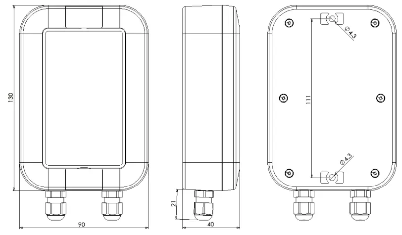
| Dimensions | 151 x 90 x 40 mm |
Power supply
| Batteries | 3.6V Lithium Thionyl battery pack (3 x AA size) |
| Typical battery life | 10 years with 1 hour transmission interval and 2 minutes measurement interval |
Measuring and data transmission
| Transmission Interval | Configurable: 5min / 10min / 15min /20min / 30min / 1h / 2h / 3h / 4h / 6h |
| Measurement Interval | Configurable: 1/2/3/4/5/10/15/20/25/30/45/60 min |
| Radio | LoRa radio technology with Murata ABZ-093 LoRaWAN modem. |
| Antenna | Internal |
| Frequency band | 863-870 MHz (LoRaWAN 1.0.2 EU band) |
| Transmission power | Max +14 dBm E.R.P. |
| Range, line-of-sight | Depends on installation location and environment, in good conditions 10 km |
Temperature measurement (Pt100)
| Sensor | Pt100 |
| Measurement range | -200…+650°C |
| Accuracy | Accuracy 0.05% rdg + 0.2 °C at 25 °C ambient |
| Thermal drift | 0.01 °C/°C |
| Cable length | <30 m |
Temperature measurement (Internal)
| Measurement range | -40°C .. +125°C |
| Accuracy | Typically ±0.5°C |
Digital inputs
| Inputs | 3 digital inputs |
Warnings
![]() The device must not be disposed in household waste. Observe local regulations concerning the disposal of electrical waste. The device may contain a battery.
The device must not be disposed in household waste. Observe local regulations concerning the disposal of electrical waste. The device may contain a battery.
Manufacturer
Nokeval Oy
Rounionkatu 107
FI-37150 Nokia
Phone +358 3 342 4810 (Mon-Fri 8:30-16:00 EET)
WWW http://www.nokeval.com/
Email [email protected]
Declaration of conformity
EU Declaration of Conformity
Object of declaration: Wireless measuring device
Model/Type: Stable
Description: Device measures temperature with external sensors and digital inputs. Device communicates using 868MHz LoRaWAN.
Manufacturer: Nokeval Oy Rounionkatu 107, 37150 Nokia, Finland
www.nokeval.com
tel. +358 33424 800
[email protected]
This declaration of conformity is issued under the sole responsibility of the manufacturer.
The object of the declaration described above is in conformity with the relevant Union harmonization legislation:
Directive (RED) 2014/53/EU Directive (RoHS) 2011/65/EU
The conformity is given based on the following harmonized standards:
RED: EN 300 220-2 V3.1.1 (2017-02)
EN 301 489-1 V2.1.1 (2017-02)
EN 301 489-3 V2.1.1 (2017-03) EMC:
EN 61326-1:2013 LVD:
EN 61010-1:2010 RoHS:
EN 50581:2012
Product is marked with CE mark to indicate compliance. Product is designed and manufactured in Finland.
Signed for and on behalf of Nokeval Oy:
At Nokia 01.06.2021 www.nakeval.com


