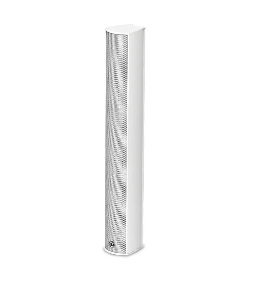
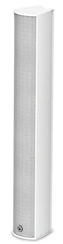
AtlasIED ATS005894E 10 Speaker Full Range Line Array Speaker System Black
Safety Instructions
Please read carefully before installing or operating.
- Read all instructions carefully
- Heed all warnings
- Assure that the speaker is securely mounted
- Always assure amplifier power is off before making any connections
- Keep instructions for future reference
- Should any questions arise after reading this document, please call Atlas IED Tech Support at 800-876-3333
Hearing Damage
CAUTION: All professional loudspeaker systems are capable of generating very high sound pressure levels. Use care with placement and operation to avoid exposure to excessive levels that can cause permanent hearing damage
Suspension and Mounting
Installing speaker systems requires training and expertise. Improper speaker installation may result in injury, death, equipment damage, and legal liability. Installation must be carried out by fully qualified installers, in accordance with all required safety codes and standards at the place of installation.
Legal requirements for overhead installation vary by municipality, please consult the Building Inspector office before installing any product and thoroughly check any laws and bylaws prior to installation. Installers that lack the skills, training, and proper ancillary equipment to install a speaker system should not attempt to do so.
Installation
- Run the wiring from the power amplifier to the location desired for mounting the ALA Series speaker.
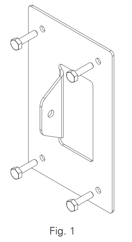
- Attach the lower wall bracket to the wall. Use a level to be certain that the wall bracket is straight. Secure the wall bracket to the wall. Be sure to use the appropriate wall anchors when attaching the bracket. Use all four screw holes for maximum integrity and safety.
Note: Hardware for attaching the wall bracket to the wall is not included.
- Attach the upper wall bracket as required.
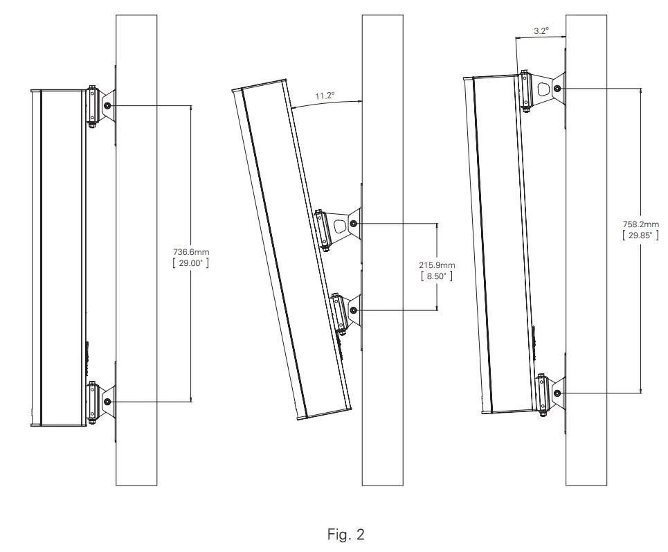
A. The location of the upper wall bracket will vary according to the angle that the speaker will be used.
B. If the speaker will be parallel to the wall, the upper wall bracket can be located 18″ (45.7cm) to 29 3 /4″ (75.6cm) center to center. Two short speaker brackets will be used; one on the top and one on the bottom.
C. For an angled installation, please refer to the table below to determine the center to center distance for the wall brackets.
ALA10TAW ANGLE C-C IN C-C CM 11.2° 8.5″ 21.59 10.6° 9″ 22.86 10° 9.5″ 24.13 9.5° 10″ 25.40 9.1° 10.5″ 26.67 8.6° 11″ 27.94 8.3° 11.5″ 29.21 7.9° 12″ 30.48 7.6° 12.5″ 31.75 7.3° 13″ 33.02 7° 13.5″ 34.29 ALA10TAW ANGLE C-C IN C-C CM 6.8° 14″ 35.56 6.5° 14.5″ 36.83 6.3° 15″ 38.10 6.1° 15.5″ 39.37 5.9° 16″ 40.64 5.8° 16.5″ 41.91 5.6° 17″ 43.18 5.4° 17.5″ 44.45 5.3° 18″ 45.72 5.1° 18.5″ 46.99 5° 19″ 48.26 ALA10TAW ANGLE C-C IN C-C CM 4.86° 19.5″ 49.53 4.74° 20″ 50.80 4.63° 20.5″ 52.07 4.52° 21″ 53.34 4.41° 21.5″ 54.61 4.31° 22″ 55.88 4.21° 22.5″ 57.15 4.12° 23″ 58.42 4.03° 23.5″ 59.69 3.95° 24″ 60.96 3.87° 24.5″ 62.23 ALA10TAW ANGLE C-C IN C-C CM 3.79° 25″ 63.50 3.72° 25.5″ 64.77 3.65° 26″ 66.04 3.58° 26.5″ 67.31 3.51° 27″ 68.58 3.45° 27.5″ 69.85 3.39° 28″ 71.12 3.33° 28.5″ 72.39 3.27° 29″ 73.66 3.21° 29.5″ 74.93 3.19° 29.75″ 75.57 
- Attach the short speaker bracket to the wall bracket.
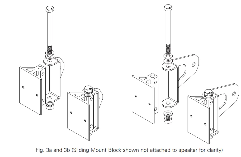
A. Position the short speaker bracket over the lower sliding mount block as shown in Fig. 3a.
B. Insert the 100mm M8 bolt through the short speaker bracket and the lower sliding mount block. Be sure to include the plain washers and one lock washer as shown.
Note: For angled installation, skip step 4C and proceed to step 4D.
C. If the speaker will be parallel to the wall, repeat steps 4A and 4B for the upper sliding mount block.
D. Position the medium speaker bracket over the upper sliding mount block as shown in Fig. 3b.
E. Insert the 100mm M8 bolt through the speaker bracket and the sliding mount block. Be sure to include the plain washers and one lock washer as shown.
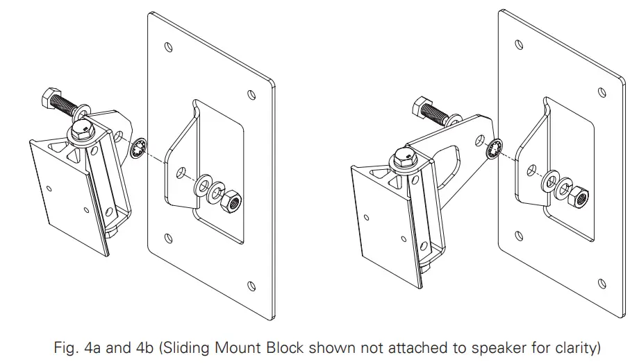
- Attach the speaker bracket to the wall bracket.
A. Insert the 20mm M8 bolt through the short speaker bracket, internal tooth lock washer, and the wall bracket as shown in Fig. 4a. Be sure to include the plain washers and one split ring lock washer as shown.
B. Insert the 20mm M8 bolt through the medium speaker bracket and the upper wall bracket as shown in Fig. 4b. Be sure to include the plain washers and one split ring lock washer as shown.
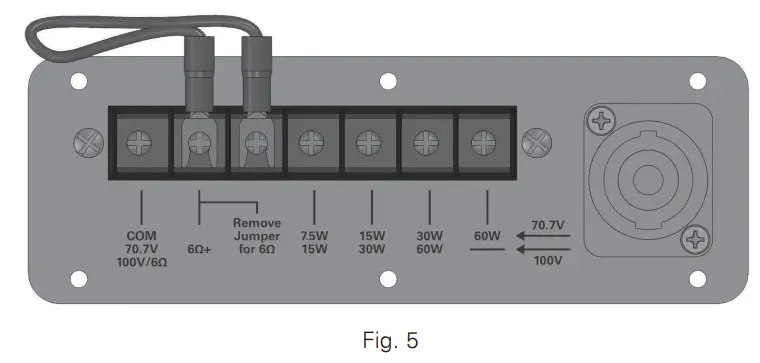
C. Adjust horizontal position of the speaker and torque all bolts sufficiently to hold position. - Establish electrical connection. All models include a built-in, high efficiency 60 Watt 70.7V/100V transformer with 7.5, 15, 30, and 60 Watt taps as shown in Fig. 5.

Note: A removable jumper and additional pole on the terminal block is included for transformer operation. The jumper must be removed for low impedance (6Ω) direct coupled operation.
Connections are provided on the terminal for both transformer and low impedance connection. An NL4 Speakon® connector is included for low impedance (6Ω) direct coupled operation.
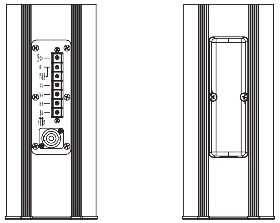
Note: When using the Speakon® input connection, the jumper must be removed from the barrier terminal. - Use the two middle terminal plate screws to secure the terminal cover (included) to the terminal plate. All applications require an IP54 (min) rated 3 /4″ (21mm) conduit or cable gland connector.

| System | |
| Type | Full Range, Column Loudspeaker |
| Operation Mode | Non-Powered Passive |
| Operating Range (-10dB) | 125Hz – 20kHz |
| Frequency Response (+/- 5dB) | 160Hz – 20kHz |
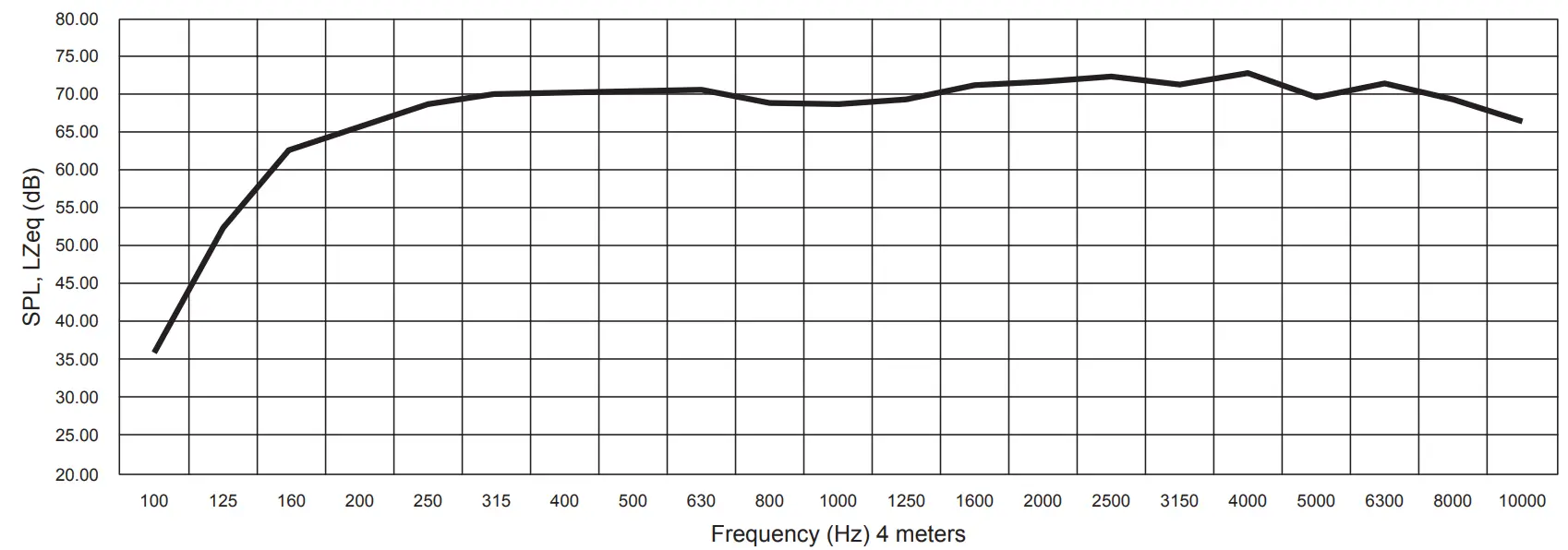
| Input Sensitivity at 1W/4m EN54-24 | 82dB |
| Max Input Ratings (6Ù) | 200 W Continuous, 400 W Program 34.7 Volts RMS, 49 Volts Peak |
| Transformer Taps – 70V | 60W (81Ù), 30W (163Ù), 15W (326Ù), 7.5W (653Ù) and Low Impedance (6Ù) |
| Transformer Taps – 100V | 60W (163Ù) RNP, 30W (326Ù), 15W (653Ù) and Low Impedance (6Ù) |
| Directivity Factor (Q) | 7.43 @ 2 kHz |
| Directivity Factor (DI) | 8.71 @ 2 kHz |
| Max SPL at 4m EN54-24 (Passive – 100V / 60W) | 96dB (±3dB) |
| Recommended Signal Processing | 90 Hz High Pass Filter |
| Recommended Power Amplification | 600W at 6Ù |
| Transducers | |
| LF Transducer Qty and Size | 10 x 3″ |
| LF Voice Coil Size | 20mm |
| HF Transducer Qty and Size | 4 x 22mm |
| HF Voice Coil Size | 20mm |
| Maximum Output | 122dB SPL (Peak 6Ù) |
| Nominal Impedance | 6Ù |
| Minimum Impedance | 5.1Ù @ 10.7 kHz |
| Crossover Frequency | 3500Hz |
| Enclosure | |
| Color | White (RAL-9016) or Black |
| Enclosure Material | Extruded Aluminum |
| Grille Material | Powder Coated Aluminum, White (RAL-9016) or Black |
| Baffle Material | Aluminum |
| Mount Material | Powder Coated CRS (Color Matches Enclosure) |
| Input Connection | Barrier Terminal For Transformer & 6Ù Inputs/ NL4 For 6Ù Input |
| Mounting / Rigging Provisions | Wall Mounting Hardware Provided |
| Ingress Protection EN54-24 | IP33C |
| Logo | Silver on Black Removable |
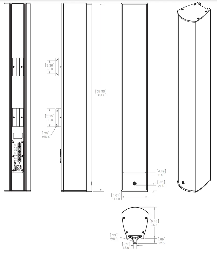
| Product Dimensions (HxWxD) | 32.9″ x 4.61″ x 5.43″ (836mm x 117mm x 138mm) |
| Shipping Dimensions (H x W x D) | 28″ x 12.9″ x 10.55″ (710 mm x 328 mm x 268mm) |
| Net Weight | Unit w/ Wall Mount Bracket= 19.6 lbs. (8.9kg) |
| Shipping Weight | 24.2 lbs (10.9kg) |
| Warranty Coverage | |
| Warranty Period | 5 Years |
NOTES:
- Power: All power figures are calculated using the rated nominal impedance.
- Frequency response and sensitivity are free field measurements.
- Recommended power amplification is 1.5X program power.
- RNP – Rated noise power
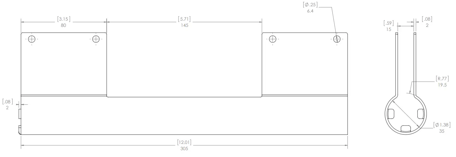
Dimensional Drawings
Frequency Response
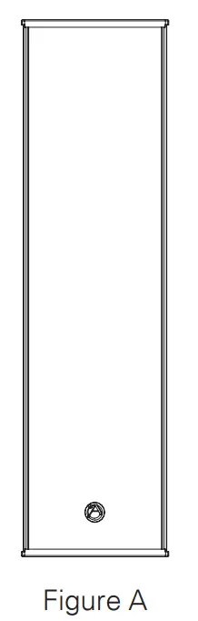
| Horizontal (Figure A) | Rotated right from the center axis of the speaker (6dB drop angle) | Rotated left from the center axis of the speaker (6dB drop angle) |
| Center Octave Band (Hz) | ||
| 500 | 119° | 115° |
| 1000 | 89° | 83° |
| 2000 | 70° | 61° |
| 4000 | 70° | 62° |
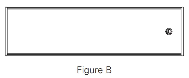
| Vertical (Figure B) | Rotated right from the center axis of the speaker (6dB drop angle) | Rotated left from the center axis of the speaker (6dB drop angle) |
| Center Octave Band (Hz) | ||
| 500 | 27° | 26° |
| 1000 | 14° | 15° |
| 2000 | 6° | 8° |
| 4000 | 8° | 7° |
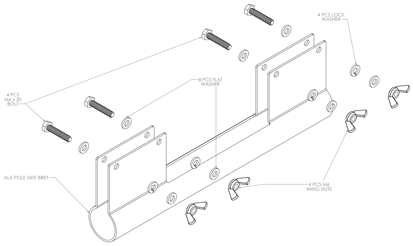
Optional Accessories
- ALAPMK – Pole Mount Kit (Not EN54-24 Evaluated)


 UK Representative
POLAR Audio Limited Unit 3, Clayton Manor, Victoria Gardens, Burgess Hill, RH15 9NB, UK
[email protected]
 EU representative:
Mitek Europe 23 Rue des Apennins 75017 Paris, France
[email protected]
Limited Warranty
All products manufactured by AtlasIED are warranted to the original dealer / installer, industrial or commercial purchaser to be free from defects in material and workmanship and to be in compliance with our published specifications, if any. This warranty shall extend from the date of purchase for a period of three years on all AtlasIED products, including SOUNDOLIER brand, and ATLAS SOUND brand products except as follows: one year on electronics and control systems; one year on replacement parts; and one year on Musician Series stands and related accessories. Additionally, fuses and lamps carry no warranty. AtlasIED will solely at its discretion, replace at no charge or repair free of charge defective parts or products when the product has been applied and used in accordance with our published operation and installation instructions. We will not be responsible for defects caused by improper storage, misuse (including failure to provide reasonable and necessary maintenance), accident, abnormal atmospheres, water immersion, lightning discharge, or malfunctions when products have been modified or operated in excess of rated power, altered, serviced or installed in other than a workman like manner. The original sales invoice should be retained as evidence of purchase under the terms of this warranty. All warranty returns must comply with our returns policy set forth below. When products returned to AtlasIED do not qualify for repair or replacement under our warranty, repairs may be performed at prevailing costs for material and labor unless there is included with the returned product(s) a written request for an estimate of repair costs before any non warranty work is performed. In the event of replacement or upon completion of repairs, return shipment will be made with the transportation charges collect.
EXCEPT TO THE EXTENT THAT APPLICABLE LAW PREVENTS THE LIMITATION OF CONSEQUENTIAL DAMAGES FOR PERSONAL INJURY, ATLASIED SHALL NOT BE LIABLE IN TORT OR CONTRACT FOR ANY DIRECT, CONSEQUENTIAL OR INCIDENTAL LOSS OR DAMAGE ARISING OUT OF THE INSTALLATION, USE OR INABILITY TO USE THE PRODUCTS. THE ABOVE WARRANTY IS IN LIEU OF ALL OTHER WARRANTIES INCLUDING BUT NOT LIMITED TO WARRANTIES OF MERCHANTABILITY AND FITNESS FOR A PARTICULAR PURPOSE.
AtlasIED does not assume, or does it authorize any other person to assume or extend on its behalf, any other warranty, obligation, or liability. This warranty gives you specific legal rights and you may have other rights which vary from state to state.
Service
Should your ALA10TAW require service, please contact the AtlasIED warranty department through the online warranty claim process.
Online Warranty Claim Processes
- Warranty submissions are accepted at: https://www.atlasied.com/warranty_statement where the type of return Warranty or Stock return can be selected.
- Once selected, you will be prompted to enter your login credentials. If you do not have a login, register on the site. If already logged-in, navigate to this page by selecting “Support” and then “Warranty & Returns” from the top menu.
- In order to file a Warranty Claim, you will need:
A. A copy of the invoice / receipt of the purchased item
B. Date of Purchase
C. The product name or SKU
D. The serial number for the item (if no serial number exists, enter N/A)
E. A brief description of the fault for the claim - Once all required fields are completed, select the “Submit Button”. You will receive 2 emails:
- One with a confirmation of the submission
- One with a case# for your reference should you need to contact us.
Please allow 2-3 business days for a response with a Return Authorization (RA) number and further instructions. AtlasIED Tech Support can be reached at 1-800-876-3333 or atlasied.com/support. Visit our website at www.AtlasIED.com to see other AtlasIED products.
Please allow 2-3 business days for a response with a Return Authorization (RA) number and further instructions. AtlasIED Tech Support can be reached at 1-800-876-3333 or atlasied.com/support. Visit our website at www.AtlasIED.com to see other AtlasIED products
Customer Support
TELEPHONE: (800) 876-3333
[email protected]